patent · US6068309
Locking wedge for a motor vechicle door lock or the like, and motor vehicle door lock with said locking wedge
30 May 2000
Page 1 — bibliographic record
United States Patent (19) 11 Patent Number: 6,068,309 Jung et al. (45) Date of Patent: May 30, 2000 54) LOCKING WEDGE FOR A MOTOR 56) References Cited
VECHICLE DOOR LOCK OR THE LIKE,
AND MOTOR VEHICLE DOOR LOCK WITH U.S. PATENT DOCUMENTS SAID LOCKING WEDGE 446,173 2/1891 Hancock ............................ 292/341.19 2,113,121 4/1938 Peterson . 292/341.15 75 Inventors: Oliver Jung, Wuppertal; Siegfried 3,415,559 12/1968 Jeavons ................................... 292/216 Reichmann, Wermelskirchen; Bernd 3,727,960 4/1973 Uemura et al..
Allefeld, Breckerfeld; Bernd 2Y------
Cly . . . . . . . . . . . . . . . . . . . . . . . . . . . . . . . . . . . . . . .
Weyerstall, Wuppital, Berthold
Huessler, Ahaus; Bernd Huster,
Zimmerman ............................ 292/216
Muenchberg; Hansjuergen Linde, 5,707,092 1/1998 Van Slembrouck ............... 292/341.19 Coburg; Uwe Neumann, Bamberg;
Heinrich Plett, Wermelskirchen; Stefan Primary Examiner B. Dayoan
Schwitters, Remscheid, all of Germany Assistant Examiner-Gary Estremsky
Attorney, Agent, or Firm Nixon Peabody LLP, David S.
73 Assignee: Robert Bosch GmbH, Stuttgart, Safran
Germany 57 ABSTRACT 21 Appl. No.: 09/147,580 The subject of the invention is a key collar for a motor 22 PCT Filed: Jun. 19, 1997 vehicle door lock or the like including a key collar Support plate fixedly attached on a Support sheet, and a collar 86 PCT No.: PCT/DE97/O1256 element Supported on the collar Support plate which, in S371 Date: Jan. 26, 1999 operation, engages a lock catch of the motor Vehicle door lock or the like. Optionally, the key collar includes an
S 102(e) Date: Jan. 26, 1999 elastomer arrangement which allows the collar element to 87 PCT Pub. No.: WO98/04797 move a limited distance relative to the collar Support plate in the plane of the collar Support plate thereby better meeting
PCT Pub. Date: Feb. 5, 1998 the different requirements of normal use conditions and 30 Foreign Application Priority Data during a vehicle crash. In operation, the collar element of a preferred embodiment is Supported on the collar Support
Jul. 26, 1996 DEI Germany ........................... 1963O 245 plate on two spaced bearing points, one bearing point with a trailing bridge in a manner that collar element can be (51) Int. Cl. ................................................ E05B 15/02 Swivelled around an axis which is perpendicular to collar 52 U.S. Cl. ................................ 292/341.17; 292/341.18; Support plate, and another bearing point with a leading 292/341.15 bridge which can be displaced in corresponding arc-shaped 58 Field of Search ......................... 292/341.17, 341.19, crank.
DIG. 55 5 Claims, 4 Drawing Sheets
Page 2
Drawing sheet — no readable text.
Page 3
Drawing sheet — no readable text.
Page 4
Drawing sheet — no readable text.
Page 5
Drawing sheet — no readable text.
Page 6
LOCKING WEDGE FOR AMOTOR of course, a much easier installation of the key collar than VECHICLE DOOR LOCK OR THE LIKE, the prior conventional installation and readjustment designs AND MOTOR VEHICLE DOOR LOCK WITH which required repeated loosening and retightening of SAID LOCKING WEDGE mounting Screws (published German Patent Application
BACKGROUND OF THE INVENTION
A conventional lock Structure with a rotary catch includ 1. Field of the Invention ing a fork catch and tensile Stressed detent pawl is also The invention relates to a motor vehicle door lock includ disclosed in the above explained prior art. The Structure ing a key collar Support plate fixedly attached on a Support shown is considered to be the Standard for conventional sheet, and a collar element Supported on the collar Support motor Vehicle door locks and the prior art shows a key collar plate where, in operation, the collar element engages a lock (i.e. a locking pin) located far above the Swivel axis of the catch of the motor vehicle door lock. More specifically, the lock catch with only one bridge in the lock latch when the invention relates to Such key collars with an elastomer lock latch is in its closed position. This has the known effect arrangement which allows the collar element to move a of transferring the shearing forces during a crash through a limited distance relative to the collar Support plate in the 15 relatively large lever arm engaging the rotary catch. plane of the collar Support plate. In addition, the present Consequently, the rotary catch must be over designed and invention also relates to motor vehicle door locks including made relatively massive to increase its strength. Such a key collar, a lock catch where the lock catch includes In addition, making a rotary catch as a disk of Solid an opening that Swivels around an axis to receive a leading material instead of a fork catch is also known in the prior art bridge of a key collar and also includes a detent pawl which (German Patent DE-C-16 78 121). In such designs, the fixes the lock catch in the closed position. rotary catch is pivotally mounted in a receSS with a periph 2. Description of Related Art eral Surface abutting the rotary catch. As a result, there is no Motor vehicle door locks are generally based on Several, bearing pin in the middle of the rotary catch and the Swivel conventionally known designs. A key collar of a motor 25 axis of the rotary catch is only virtual. The rotary catch is vehicle door lock is generally mounted on a door post or a fixed axially by the bottom surface of the recess and by a part of the frame (for example, the B column or the C cover that includes an impression in the area of the center column). Usually, the key collar is mounted using mounting point of the rotary catch on the cover which limits the sliding Screws which are inserted through insertion openings pro friction between the rotary catch and the cover. Vided in the Side flanges of the key collar and Screwed into Generally in the prior art, a key collar used in the motor threaded openings in the door posts. The lock housing of vehicle door lock is designed to withstand large forces these motor vehicle door locks which house the various during a vehicle crash. This entails over dimensioning of the components of the door lock, may be made from one or two components and do not provide the optimum configuration parts and is mounted in a similar manner using mounting for normal, everyday operation.
Screws on the corresponding body part which is generally 35 SUMMARY OF THE INVENTION the front plate of a motor Vehicle door. For a long time, it has been assumed in the art that it is important to keep the Therefore, a primary object of the present invention is to relative positions between the key collar and lock housing provide a key collar, and in a corresponding manner a motor constant as much as possible in order to ensure that there is vehicle door lock with this key collar, that better meets the always an accurately determined relative engagement posi 40 differing requirements of operation during normal use and tion of the two parts of the motor vehicle door lock. during a vehicle crash.
In key collar and motor vehicle door lock designs on The aforementioned object is achieved in a key collar for which the present invention is based (German Utility Model a motor vehicle door lock including a key collar Support DE-U-88 06819), the comfort requirements of the motor plate fixedly attached on a Support sheet, and a collar vehicle user with regard to noise abatement have become 45 element Supported on the collar Support plate where, in important. In accordance with the prior art, the flanges of the operation, the collar element engages a lock catch of the collar element which project laterally are inserted into an vehicle door lock. The key collars include an elastomer elastomer arrangement in a trough-Shaped collar Support arrangement which allows the collar element to move a plate So that there is no direct contact bridge for Solid-borne limited distance relative to the collar Support plate in the noise between the collar element and the collar Support 50 plane of the collar Support plate. The movement is resisted plate. The collar Support plate itself is attached, as explained by a frictional force and the collar element remains in the previously, to the mounting sheet with mounting Screws. displaced position relative to the collar Support plate without This embedding of the collar element in the elastomer any additional force. In addition, the present invention also arrangement necessarily results in allowing a limited amount provides motor vehicle door locks with Such a key collar, a of movement by the collar elements. Therefore, the collar 55 lock catch where the lock catch includes an opening that elements may move a little to the top or bottom, to the front Swivels around an axis to receive a leading bridge of a key or back, depending on the compliance of the elastomer collar, and a detent pawl which fixes the lock catch in the arrangement. This is not inherently desirable, but in View of closed position.
the Small deflection of less than +/-1 mm, the movement can In the present invention, the known prior art float bearing be regarded as an acceptable compromise. 60 of the collar element is used in an elastomer arrangement to In addition, prior art key collars for motor vehicle door Specifically Support the collar element relative to the collar locks including a key Support plate with a permanently Support plate. This allows a certain degree of relative deformable section is also known (German Patent DE-C-30 displacement and thus, always allows automatic alignment 26 147). In this design, the collar element more or less of the location of the key collar relative to the location of the adjusts itself in the installation of the motor vehicle door and 65 lock catch in the motor vehicle door lock as the motor then, may be fixedly mounted in the adjusted position by vehicle door is closed. The movement which was accepted tightening the mounting Screws on the Support sheet. This is, as tolerance in the prior art, is specifically designed and used
Page 7
within wider limits in the present invention, thereby elimi in the closed position, lying only slightly near the line of nating the adjustment and readjustment of the key collar action of the shearing forces which occur in operation, Said during mounting. Currently, the motor vehicle doors are line crossing the Swivel axis.
generally fitted very exactly due to the Small body gap The teaching of the invention is presented in the context requirements. In this embodiment, the maximum displace of motor vehicle door lockS. However, in a corresponding ment allowable during operation of the vehicle door is manner, the present invention may also be effectively limited to +/-3 to 6 mm and preferably, is +/-4.5 mm. applied to motor vehicle hood locks, tailgate locks, etc., and Although the prior art discloses key collars that can be the motor vehicle door lock discussion below should always moved or Swivelled in a Straight line, or optionally, can be be understood in the comprehensive Sense to apply to the moved with a cam disk in order to aid in the locking other applications noted.
function, these designs differ from the present intention in In the following the invention is explained in greater that in these designs, the vehicle door is pulled tightly into detail using drawings which Show, as an example only, three its final closed position by the corresponding displacement embodiments of the invention.
of the key collar and not by moving the rotary catch.
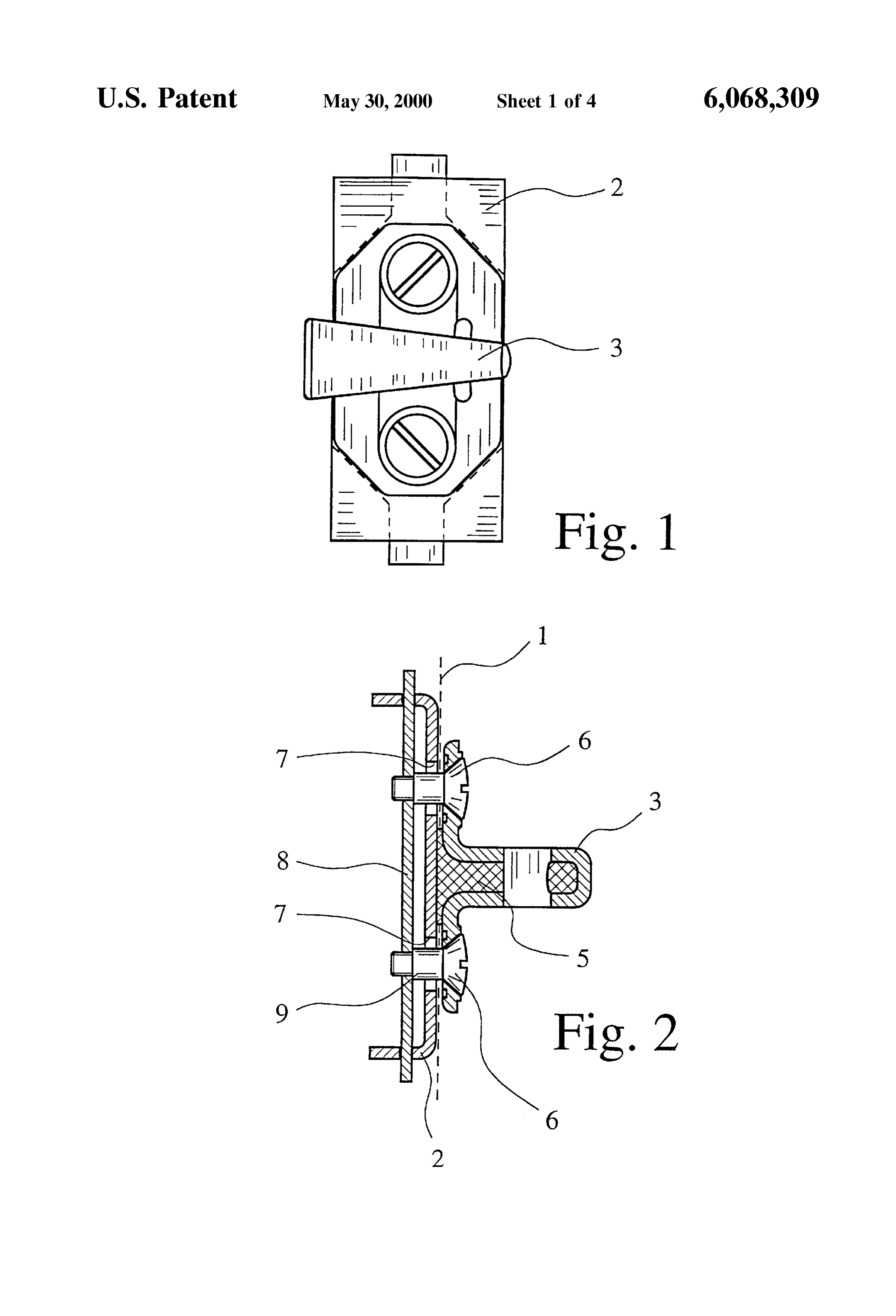
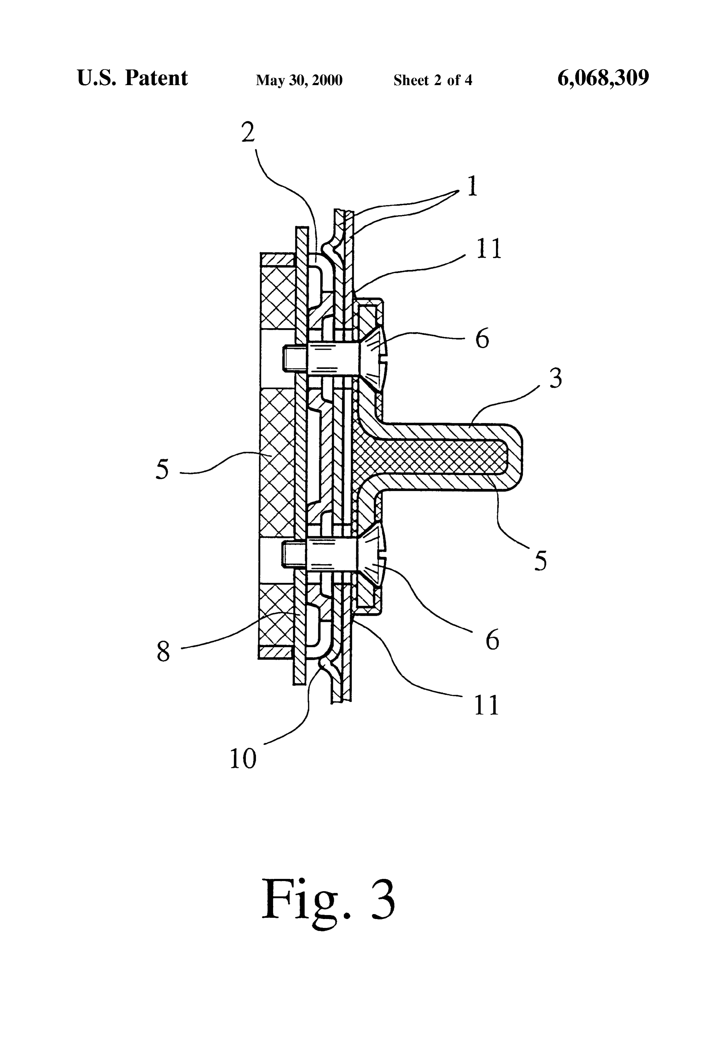
Therefore, this type of movement of the key collar is not 15 BRIEF DESCRIPTION OF THE DRAWINGS related to the collar displacement of the present invention, but rather performs an entirely different function. In FIG. 1 is an elevation view a first embodiment of a key particular, the collar is moved in order to close the vehicle's collar in accordance with the invention; door and does not Serve to ensure an accurate relative FIG. 2 shows the key collar of FIG. 1 in a section taken positioning of the key collar and lock catch. along a transverse center axis,
In another embodiment of the present invention, the key FIG. 3 shows a view corresponding to that of FIG. 2, but collar acquires an additional degree of freedom by the collar of another embodiment of a key collar in accordance with element being able to Swivel, to a limited degree, around the the invention;
trailing bridge So that the leading bridge can execute arc 25 FIG. 4 shows a third embodiment of a key collar in shaped, up and down motion when the lock catch enters the accordance with the invention which includes a dynamized receiving opening. In this way the leading bridge can be key collar;
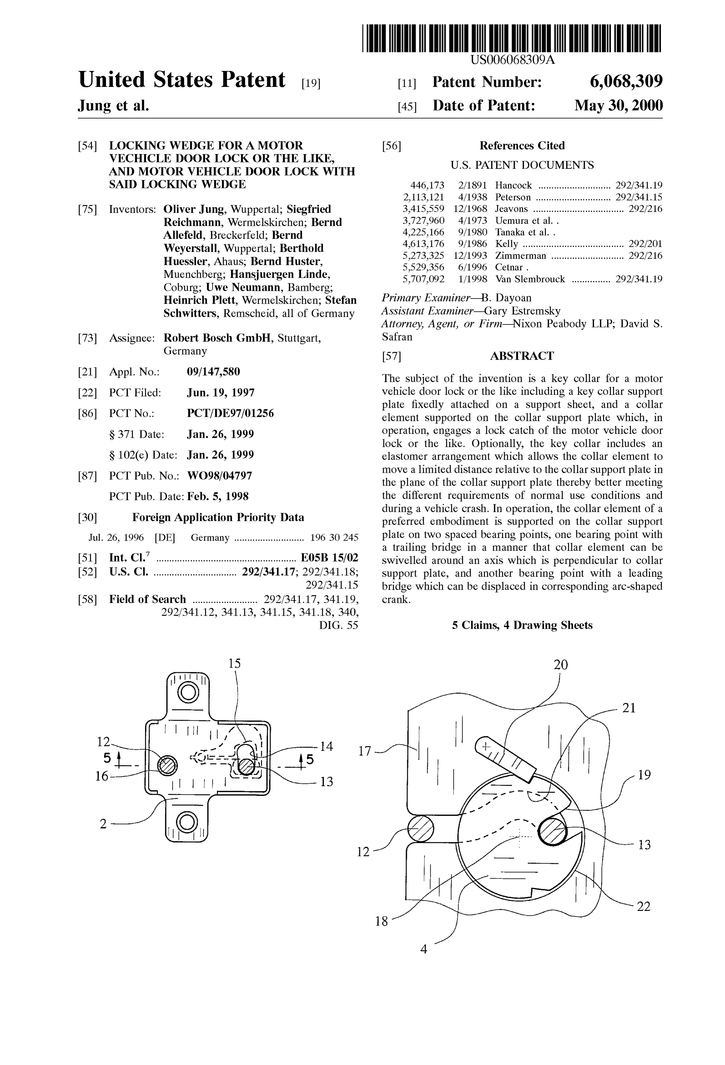
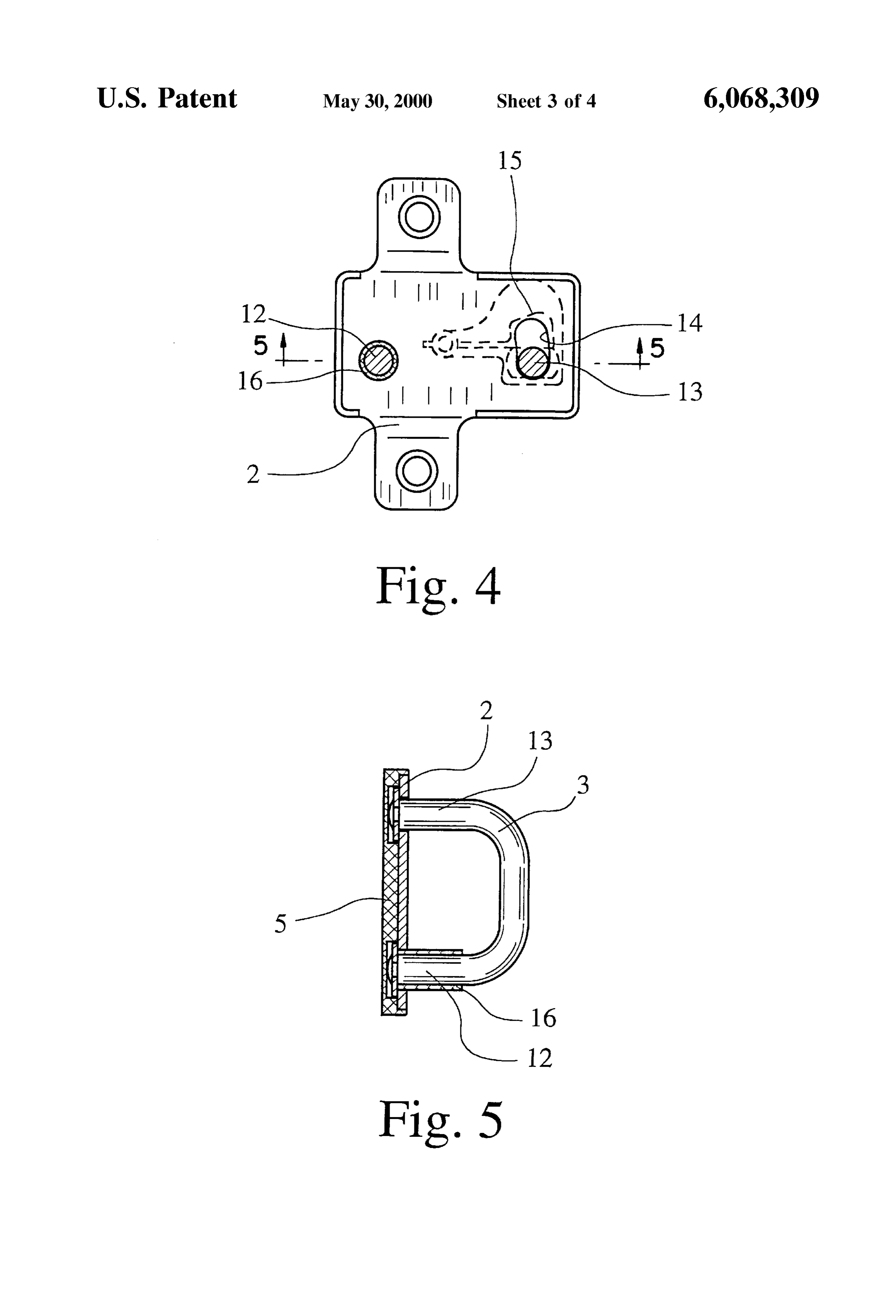
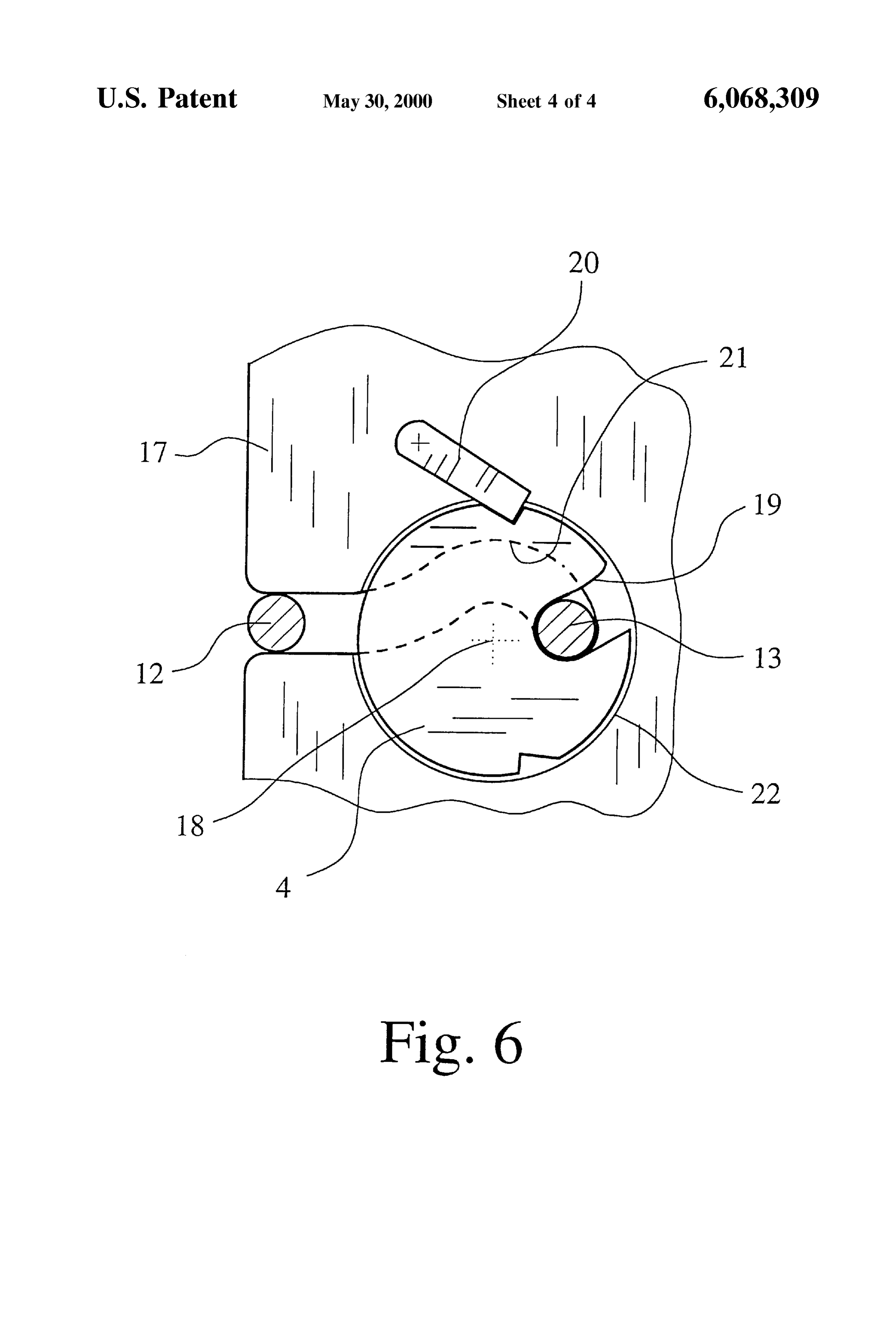
Swivelled around the Swivel axis of the lock catch when the FIG. 5 is a partial sectional view of the key collar of FIG. motor vehicle door is closed. 4, the collar Support plate being Sectioned along line 5-5 in When the lock catch reaches its closed position, the lock FIG. 4; and catch is fixed by the detent pawl. There is a minimum lever FIG. 6 shows the interaction of the key collar shown in arm relative to the Swivel axis of the lock catch which allows FIGS. 4 & 5 with a lock catch.
the operation of the lock catch. The present embodiment as applied to motor vehicle door lockS is especially significant DETAILED DESCRIPTION OF THE in that in the closed position, the Swivel axis of the lock 35 INVENTION catch lies directly on the connecting line of the two bridges of the collar element of the key collar. In the following, the present invention is described using With a key collar in accordance with the present the example of a motor vehicle door lock. AS noted invention, numerous advantages are achieved over the prior previously, however, the present invention can also be art. The dimensions of the lock catch can be reduced and the 40 applied to other locks including hood locks, gate locks and axial distance between the detent pawl and the lock catch tailgate locks on motor vehicles. The key collar shown in can also be reduced thereby reducing the construction size of FIGS. 1 and 2 is intended and Suited for use in a motor the motor vehicle door lock overall. The direction in which vehicle lock or the like. The general concepts related to the opening and Shearing forces act with the door closed motor Vehicle door locks and key collars have been dis proceeds with the minimum possible lateral distance from 45 cussed previously in the above Sections. In principle, the the real or virtual Swivel axis of the lock catch So that the teaching of this patent application can also be applied to key Shearing forces can be optimally routed into the receiver. AS collars with only one bridge which is also known as a a result, the lock catch is made simpler, and possibly other locking pin. Therefore, this one bridge design incorporating materials can even be used in the design. At the minimum, the present features should also be considered an embodi the lock catch may be made much thinner with the same 50 ment of the present invention discussed below. resistance to shearing forces during a crash as convention The key collar, first of all, has a collar Support plate 2 to ally designed lock catches. be fixed on a support sheet 1, which is shown by the broken In the above described embodiment of the key collar line of FIG. 2, and a collar element 3 supported on the collar including a Swivel axis of the lock catch lying directly on the Support plate 2. In operation, the collar element engages a connecting line of the two bridges of the collar element of 55 lock catch 4 of the motor vehicle door lock as shown in FIG. the key collar, the disc-shaped lock catch known in the art 6. An elastomer arrangement 5 is shown in collar element 3 becomes especially Suitable. The arc distance between the and conforming to Support sheet 1.
forward Stop and the main Stop on the outer periphery of the Here, it is shown that collar element 3 is supported to lock catch is much larger than in the prior art with classical allow certain amount of displacement relative to the collar fork catches in which the engagement point remains at a 60 Support plate 2 in the installed State. This is made especially distance from the Swivel axis. clear by FIG. 2 which shows mounting screws 6 which For the sake of completeness it should be pointed out here penetrate longitudinal holes 7 in collar Support plate 2. that the key collar can also have the form of a locking pin The embodiment shown in FIG. 2 includes a collar which has only one bridge. What was explained above element 3 being attached to a retaining plate 8 So that, regarding the connecting line of the two bridges of the collar 65 between the collar element 3 and the retaining plate 8, there element of the key collar relative to the Swivel axis of the is a predetermined and defined distance. In the embodiment lock catch can be modified in this case by the locking pin, shown, this distance is defined by spacer collars 9 on
Page 8
S 6 mounting ScrewS 6. In the installed configuration, the Sup According to the preferred teaching, on following bridge 12, port sheet 1 is located between the retaining plate 8 and the a bearing sleeve 16 is provided for swivel support of the collar element 3. It can be seen that the retaining plate 8 is collar element. FIG. 5 shows elastomer arrangement 5, Supported to allow displacement relative to the collar Sup which is inserted on the rear Side and which has no addi port plate 2. In fact, as a result of longitudinal holes 7, the tional function in the present embodiment. unit consisting of collar element 3 and retaining plate 8 can It can be assumed that features of the embodiment of the be shifted up or down relative to collar support plate 2. This key collar as shown in FIG. 1 or FIG. 3 and the features of shifting is resisted by the frictional contact and the Spring the embodiment as shown in FIGS. 4 and 5 can be combined action of the elastomer arrangement 5 on Support sheet 1. to provide a key collar which is Supported to float and which Therefore, in this embodiment, when the motor vehicle door is also self adjusting. In Such an embodiment, the elastomer is closed for the first time, the collar element 3 moves arrangement 5 in FIG. 5 would also acquire an additional together with the retaining plate 8 up or down relative to function in that it would then provide the frictional forces on collar Support plate 2 Such that an optimum fit is achieved. the Support sheet 1 as described previously. Thus, with the present invention, adjustment and readjust FIG. 6 illustrates the key collar as shown in FIG. 4 in ment of the key collar is no longer necessary. 15 operation and collaborating with a lock catch 4 in the motor As an example, the embodiments in FIGS. 1 and 2, on the vehicle lock. In this figure, the housing 17 is shown with the one hand, and FIG. 3, on the other, may allow a deflection Swivel axis418.
lock catch Supported therein So as to Swivel around a real
The lock catch 4 includes an opening 19 for of +/-3 to 6 mm, which is the maximum deflection allow able during use. In this embodiment, the deflection is receiving the leading bridge 13 of the key collar. The figure also shows a detent pawl 20 which fixes the lock catch 4 in preferably +\-4.5 mm relative to the neutral or middle the closed position and can also be used in conjunction with position, which is shown in FIGS. 1 and 3.
FIG. 3 illustrates another embodiment of the present the embodiments of the key collars discussed and illustrated invention, clarifying the installation position of the key previously. FIG. 6 also shows the lock catch 4, which is disk-shaped. The disc-shaped lock catch 4, which is known collar of FIG.1. The collar support plate 2, such as the one 25 in the prior art, is pivotally mounted in a receSS 22 as shown in FIG. 1, comes to rest between retaining plate 8 and indicated. AS is apparent to those skilled in the art, this collar element 3. In both embodiments, the collar support invention can also be easily used in conventional fork catch plate 2 is made in the manner of a trough or a cage and the designs with a virtual Swivel axis.
retaining plate 8 is Supported to move therein against the friction force exerted by the Spring action from the elastomer of The a embodiment shown illustrates the Special advantage disc-shaped lock catch 4 in the implementation of the arrangement 5. In this way, the key collar of the present invention is adjusted into its intended position when the teachings of this invention. The leading bridge 13 of the key collar traverses a relatively wide path between the entry motor vehicle door is closed for the first time and is retained in the position during operation as a result of frictional force. point (not shown) at the receiving opening 19 to the closed or blocked position shown in FIG. 6 where the detent pawl
In the embodiment shown in FIG. 3, a second elastomer 35 20 is at the main stop of rotary catch 4. In this regard, FIG. arrangement 5 (or Spring element) is positioned in the 6 illustrates that the housing 17 includes an inlet slot 21 for receiver of collar Support plate 2. In this embodiment, the receiving the collar element 3 of the key collar which runs frictional force occurs between retaining plate 8 and collar in an arc shape around the Swivel axis 18 of lock catch 4. The Support plate 2. In addition, as shown in the figure, the collar arc shape of inlet slot 21 Smoothly corresponds to the path support plate 2 on support sheet 1 is fixed between beads 10 40 of the leading bridge 13 of the key collar in the receiving which prevent its displacement to the top and bottom. opening 19 of the rotary catch 4. The location of the main FIG. 3 also shows that the collar element 3 is provided Stop and the forward Stop on rotary catch 4 illustrates that, with Spring projections 11 on the Side facing collar Support when made as a fork catch, there would have to be a very plate 2 at the outside edge that provide tolerance compen wide fork catch legs that takes into account this displace sation. In the embodiment shown, the Spring projections 11 45 ment. Accordingly, the main Stop and the forward Stop can are formed by extrusion molding of collar element 3 with be produced more easily and feasiblely with disc-shaped injectable plastic. lock catch 4 of the embodiment shown. Another embodiment of a key collar in accordance with It is important to note that, due to the above explained the present invention and its operation is shown in FIGS. 4, operation of the key collar in lock catch 4 So as to be fixed 5 and 6 which also illustrate the collaboration of the key 50 in the closed position, the Swivel axis 18 of lock catch 4 lies collar with a lock catch 4. This will now be explained with directly on the connecting line of the two bridges 12 and 13 reference to the combination of all three drawings. More of collar element 3. This has the advantages explained above Specifically, the collar element 3 is Supported on collar in the general part of the description which need not be Support plate 2 on two spaced bearing points So that, at one repeated here. FIG. 6 shows clearly that the proximity of bearing point with trailing bridge 12, the collar element can 55 Swivel axis 18 to the connecting line leads to application of pivot around an axis which is perpendicular to collar Support the shearing forces, for the most part, directly to Swivel axis plate 2, and at the other bearing point with leading bridge 13, 18. The remaining minor offset is a sufficient lever arm to the collar element can be displaced in a corresponding provide the force necessary to allow the lock catch 4 to be arc-shaped slot 14. Thus, a floating collar element 3 is opened.
provided where the leading bridge 13 can deflect upwards 60 We claim:
within the arc-shaped crank 14 as shown in FIG. 4. In this 1. Motor Vehicle door lock comprising a housing and a embodiment and according to the preferred teaching, the key collar, Said housing including a lock catch Supported leading bridge 13 is engaged by a Spring 15 which always therein to Swivel around a real Swivel axis and a detent pawl returns the leading bridge 13 to its neutral position. The which fixes said lock catch in a closed position, Said lock spring 15 may be made from a bendable plastic. FIG. 5 65 catch including a receiving opening for receiving a leading further illustrates that collar element 3, in the preferred bridge of Said key collar, Said key collar including a collar embodiment shown here, may be easily made as a clip. Support plate fixed on a Support sheet, and a collar element
Page 9
Supported on Said collar Support plate, Said collar element, in element of the key collar, Said inlet Slot defining an arc use, operatively engaging Said lock catch; wherein Said around the Swivel axis of Said lock catch. collar element is Supported on Said collar Support plate on 3. Motor vehicle door lock as claimed in claim 1, wherein two bearing points, a first of Said bearing points providing a Spring is provided which exerts a force urging Said leading pivotal connection for a trailing bridge of the key collar bridge into a neutral position. which is pivotable around an axis perpendicular to the collar 4. Motor vehicle door lock claimed in claim 1, wherein Support plate and a Second of the bearing points receiving
Said leading bridge which is displaceable in an arc-shaped Said collar element is made as a clip and Said following slot; and wherein Said lock catch is fixed by the detent pawl bridge is provided with a bearing sleeve. in the closed position thereof at a location in which said 5. Motor vehicle door lock as claimed in claims 1, Swivel axis lies approximately on a line connecting the wherein Said lock catch is disc-shaped. leading and trailing bridges of the key collar.
2. Motor vehicle door lock as claimed in claim 1, wherein
Said housing has an inlet slot for receiving Said collar
Provenance
- Collection
- Cited prior art
- Original PDF
- patentimages.storage.googleapis.com →
- Filed
- 1997-06-19
- Pages
- 9
- Method
- pdftotext (the PDF's own text layer) + pdftoppm 300dpi page scans
- Source
- Google Patents bibliographic record
- Granted
- 2000-05-30
- Inventors
- Oliver Jung; Siegfried Reichmann; Bernd Allefeld; Bernd Weyerstall; Berthold Huessler; Bernd Huster; Hansjuergen Linde; Uwe Neumann; Heinrich Plett; Stefan Schwitters; Robert Bosch GmbH
- Transcribed from
- patentimages.storage.googleapis.com →