patent · US2106346
Power plant
25 January 1938
Page 1
Drawing sheet — no readable text.
Page 2
Drawing sheet — no readable text.
Page 3
Drawing sheet — no readable text.
Page 4
Patented Jan. 25, 1938
UNITED STATES PATENT OFFICE
POWER PLANT
Hans Gleichmann, Falkenhain, near Spandau,
Germany, assignor to Siemens-Schuckertwerke
Aktiengesellschaft, Berlin-Siemensstadt, Ger many, a corporation of Germany
Application September 28, 1933, Serial No.
many September 30, 1932
My invention relates to steam power plants and Figs. 1 to 6, inclusive, are diagrams facilitating it has for an object to provide apparatus of this an understanding of my invention; and character with improved means for controlling Figs. 7 and 7A together show an outline of a the generation of steam. power plant incorporating my improvements. A further object of my invention is to provide The regulation of a power system involves both a power plant wherein the steam generator is the production and consumption of energy. Since capable of supplying steam at pressures which energy is initially produced in the boiler or gen increase and decrease with increases and de erator, regulation of the system is not completed
breases in load so that the weight-volume may merely by regulation of the prime mover, or en be varied suitably to the load with maintenance ergy transformer. Accordingly, my improved O of approximately constant volume at variable System contemplates the use of means responsive loads. to load imposed on the prime mover for control A further object of my invention is to provide ling the steam generator in order that the genera a steam generator of the forced passage type and 5 delivering steam to the prime. mover and having tion of steam may be coordinated with power
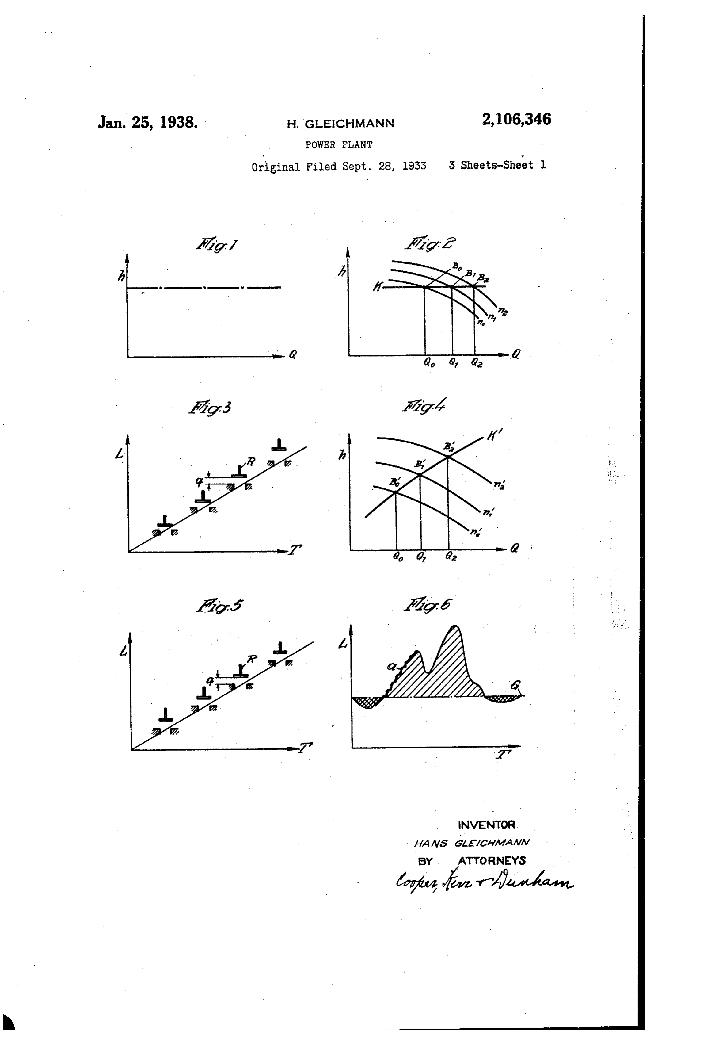
the supplies of feed water and heat for the gen It is customary practice to control the boiler erator under control of the load imposed on the or generator so as to supply steam of approxi prime mover. v mately constant properties and to vary the sup A further object of my invention is to provide ply of such steam to the prime mover by means 20 a power plant including a steam generator of the operated in response to load imposed thereon. 20 forced passage type supplying steam to a prime If, as shown in Fig. 1, the quantity, Q, of steam nover and which is arranged to operate at sub is generated at pressure, h, and if the quantity of stantially constant pressure up to a predetermined steam produced in the generator is equal to that load and at variable pressures thereabove. Supplied to the prime mover, then a horizontal 25 A further object of my invention is to provide line is obtained, that is, the pressure of the work a power plant including a forced passage steam ing medium developed by the generator is main 25 generator and a prime mover with a governor tained uniform for all loads. This may be ac control valve in the steam supply line for the Complished by increasing the Supply of heat and prime mover and means responsive to differen consequently the production of steam with in 30 tial pressure across the valve for controlling the crease in load and vice versa. supplies of feed water and heat to the generator. 30 While slight fluctuations are unfavorable in
A further object of my invention is to provide actual practice, yet the ordinary standard steam a variable pressure cycle power plant including generator, operating in the above manner, dif a steam turbine having steam bled therefrom fers from the type of generator having forced 35 for operating an auxiliary turbine, the latter passage of operating medium, for, with the lat 35 driving the auxiliaries for supplying feed water, ter type, the capacity for storage of water is very fuel and air to the steam generator. limited; and, consequently, in operation, the A further object of my invention is to provide Quantity of water supplied by the feed pump must a power plant including a steam generator sup be made equal to the quantity of steam leaving 40 plying steam to a prime mover and wherein the the boiler. Accordingly, a boiler of the forced auxiliaries for furnishing feed water, fuel and air passage type must be regulated in accordance 40 to the generator are operated in accordance with with the load so as to maintain a linear relation the load imposed on the prime mover. as between the quantity of water supplied and A further object of my invention is to provide the quantity of steam consumed. This relation a steam generator supplying steam to a prime ship is shown in Fig. 2, it being assumed that the mover, the generator being operated in such man boiler feed pump is of the centrifugal type and . ner as to supply steam at pressure dependent Serves to feed as well as to maintain the forced upon the load and at approximately constant passage of operating medium. The pressure of 50 temperature for all loads. Operating medium in the generator, and includ ing steam issuing therefrom, may be maintained 50
These and other objects are effected by my substantially constant by suitable pressure-limit invention as will be apparent fron the following ing means associated description and claims, taken in connection with with the pump. the accompanying drawings, forming a part of boiler In Fig. 2, the boiler load Q of a forced passage this application, in which: is plotted against the boiler pressure h, the constant boiler pressure prevailing at different 55
Page 5
loads being represented by the horizontal line K. variation in volume or velocity of steam. Instead The three curves no, n1, and n2 represent three of having an admission valve whose passage area. different speeds of the centrifugal pump and the depends upon the load, as with the constant pres relationship between pressure and quantity of sure type plant and as shown in Fig. 3, in accord 5 ance with my invention an admission or control feed. The points of intersection Bo, B1, and B2, valve, as such, is not essential; and, if one is used, of these curves with the straight line K determine as illustrated the operating points and/or the speeds of the tially the sameinpositionFig. 5, it may occupy Substan defining Substantially the centrifugal pump for the corresponding boiler same inlet area throughout the load range, the loads Q0, Q1, and Q2. necessary variation requirements to meet load O With a boiler of the constant pressure type, irrespective of the manner in which it is regul variation being taken care of by variation in pres" sure of steam delivered from the generator.
lated to provide steam at constant pressure, it is Variable pressure operation, as compared with necessary to vary the admission of steam to the throttling in a single steam path, has the ad prime mover in order that the latter may be op vantage of higher efficiency in that no fall of 5 erated suitably to carry the load. In Fig. 3, the pressure occurs without performance of Work. load Li is plotted against time T, it being assumed An important advantage of the variable pressure that the load increases with increase in time.
Since the steam is at constant pressure and ten arrangement is that the turbine may be con perature, it necessarily has a specific volume and structed with a single steam path without the use heat content dependent thereon; and, in conse of controlled nozzle groups or by-passing, there 20 quence, if the output of the prime mover is in by reducing the complexity of the turbine Struc creased the quantity of steam admitted thereto ture, the cost thereof, and reliability would be must also be increased. Hence, in Fig. 3, the in improved. The reason for the possibility of a let cross-section q is dependent on the load, the relatively simple and symmetrical structure is regulating member R operating to vary the inlet that while the flow varies with variation in pres sure, the volume and velocity remain approxi area in accordance with the load.
The principal object of the present invention is mately constant under variable load conditions, to provide a novel method of regulation as com the specific volume varying inversely as the pres sure. In other words, without any change in 30 pared to methods hitherto known and carried out velocity or volume of steam flowing, the quantity 30 according to FigS. 1 and 2. To Satisfy fluctua of steam and heat content per unit of volume tions of load in high-preSSure plants, in accord may be varied by varying the pressure. Another ance with my invention, the steam generator is advantage for variable pressure operation is that, operated to supply steam under pressure depend for the practicable range thereof, the adiabatic ent upon the load and at Substantially constant heat drop is approximately constant for variable temperature, the pressure increasing with in load conditions. It will be found that, upon refer crease in load and vice versa. In Fig. 4, the line ence to the temperature-entropy diagram, the K is the characteristic pressure line, it being again assumed that the boiler is of the forced condenser absolute pressure line or lines are ap passage type and that feed water is supplied proximately parallel to the temperature curve thereto by a centrifugal pump. As compared to intersecting different pressures, whereby the lines 40 Figs. 1 and 2, the pressure h of the operating of available heat drop due to adiabatic expansion medium is not constant over the entire range of which are drawn from the maximum temperature line at different pressures to the condenser pres load Q, but it increases with increase in load and sure line or lines are all substantially equal. Since vice versa. The curves no, n.11 and n2 in Fig. 4 show the relationship between the pressure and the adiabatic heat drop is nearly equal over wide 45 variation the quantity delivered for three different pump turbine, except in loads, the steam velocity through the Speeds. The points of intersection B10, B11, and the same over the for the last few stages, is nearly B2 of the characteristic line Kll with these curves same variation in load. If the determine the corresponding operating points tically turbine speed remains constant, this gives prac a constant velocity ratio of blade Speed to 50 and/or the Speeds of the centrifugal pumps at steam speed. As this ratio is of primary im the corresponding boiler loads Q0, Q1 and Q2.
From Figs. 1 to 4 inclusive, it will be seen that portance in the efficiency of the turbine, the my improved steam generator, instead of supply turbine efficiency will be nearly constant over the ing steam at constant pressure, supplies such range of load variation.
If it is assumed that a turbine is So designed 55 55 steam at variable pressure and constant tempera as to operate at 35 atm. and at a temperature of ture, the pressure depending upon the load. War 450° C. with the optimum vacuum and the opti iable pressure cycle operation may be secured mum efficiency, it then develops, with a certain with any forced passage boiler so long as my in weight of steam, a given power. If the power proved controlling features are used. The heat 60 ing Surface may be of the once-through tubular increases to a peak four times the normal value, 60 then it can type or elements thereof may be connected to develop the correspondingbe carried only if the boiler can drums or the like. Variation in pressure, such the weight of steam. If that the pressure increases proportionately to the constant boiler pressure is increased to 160 atm. at a load causes variation in specific volume of steam increasingtemperature of 450° C. by utilizing thc pressure characteristic, the specific
Supplied to the prime mover, the specific volume volume of the varying inversely with the pressure. In conse However, thissteam means decreases from 0.095 to 0.018.
that the quantity of steam quence of variability of specific volume, it will be flowing through the boiler
Seen that the flow of steam supplied to the prime five times the normal value,may be increased to mover may be varied to Suit the load require considerably the velocity of thewithout steam in increasing the boiler 70 ments with maintenance of substantially con and-with the exception of a particular case here stant volume at all loads, with the result that in after described-in the turbine. It is, of course, flow passages, including passages in the turbine, presumed that the quantity of heat correspond have a much wider utility for the passage of
Steam, it being possible, without any variation in ing to the increased quantity of steam can oe developed in the furnace and imparted to the 5 Such passages, to vary the weight flowing without
Page 6
boiler system. This may, however, be easily ac These ranges of regulation are indicated in the complished. Consequently, utilization of the in diagram of Fig. 6 by the cross-hatched area. creasing pressure characteristic of the boiler The plant is regulated in response to a load or causes a greater weight of steam to be forced speed effect of the rotating apparatus, Such effect 5 through the turbine-as a result of the Specific volume of steam decreasing with increasing pres being exerted on the feed water and heat supply sure-the greater the pressure in the boiler will means so that, with increase in load, the pressure be. This results again in a novel method of of steam furnished from the boiler to the prime reg'2 aging the prime mover connected with the mover is increased and vice versa, the pressure O boiler, insofar as the prime mover governor must being sufficient to carry the load at approximately constant prime nover Speed. With the plaint balance the fluctuations of power of the prime regulated in this way, it will be apparent that lO mover which are not equalized by the variable the steam speed in the boiler, the Superheater, pressure characteristic of the steam generator. Supply conduits and the turbine, except for the If, in the diagram of Fig. 5, the load I is plotted last stages, remains substantially constant, where against the time T an increasing straight line as the Velocity of water in the boiler and that of results similar to the diagram of Fig. 3 and if the Steam positions of the regulating member R of the prime Steam in the condenser increases, the velocity of mover are plotted, a constant opening q of the turbine.also increasing in the last stages of the valve over the entire range of load is attained as 20 compared to the conditions shown in the diagram Control of the plant to secure operation in the of Fig. 3. above manner, that is, so as to generate and sup 20 ply steam to the prime mover at a pressure which
While, with the operating methods hitherto increases known, the operating nedium supply to the prime at with increase in load and vice versa, and mover is determined by the position of the inlet substantially constant temperature, may bese valve, the position of the valve with the present cured in a variety of ways. For example, a speed method has no influence on the Supply of the governor or electrical apparatus responsive to a operating medium, or, at most, influences the Sup load or Speed effect may be used. The speed or ply only to the extent of balancing the slight load effect may be exerted on the feed water sup fluctuations of power which, as a result of the ply means to secure the required pre?sure and on 30 inertia of the boiler System, cannot be equalized the combustion media supply means to secure by the latter. The above described behavior of adequate heat release for different loads. 30 regulation is of very great importance for the The Speed or load effect is preferably exerted operation of the turbine, as an entirely smooth On a valve between the boiler and the prime mover curve of the Specific consumption of steam is ob or turbine, the differential pressure across the 35 tained; i. e., the increase in specific consumption valve being used as a regulating impuise for feed of steam or increase in volume and velocity, is Water, fuel and air. The regulating valve is nor 35 slight with increasing load. According to a rough mally not completely open so as to provide a re estimate, the increase in the specific consumption Serve Supply of energy which is immediately of Steam from the optimum point of the turbine available in case of sudden increase in load in 40 to approximately four times the maximum load which case the governor, or its equivalent, Opens amounts to about 12 per cent, and, under some the valve wider to make the energy reserve im circumstances, still less, whereas, in the case of mediately effective to carry the increased load. a plant operating in the manner hitherto known, AS the valve is opened wider, the differential preS Sure thereaCross changes, and the latter results on the basis of a constant state of inlet steam, in increased supplies of fuel, air and water to an increase by 30 to 40 per cent takes place.
Regulation of this character has, moreover, the meet the new load condition. With attainment advantage that the design of the turbine is great of operating conditions suitable to the new load, ly simplified and the cost of manufacture is the regulating valve is restored to its normal position.
minimized.
Graph 6 in which the output L is plotted If there is a sudden decrease in load, the valve against time T, as in diagrams of Figs. 3 and 5 is moved in a closing direction, preventing over Speeding of the prime mover, and the resulting indicates, however, at the same time an operating increase method which has proved to be in many cases in differential pressure causes the rates particularly desirable; that is to say, the use of of Supply of media to the boiler to be reduced 55 Variable pressure only above a predetermined until equilibrium is reached, with the pressure base load which is indicated by the horizontal reduced suitably to the new load and the valve line G. The boiler and the prime mover are so restored approximately to its normal position. dimensioned as to have the best efficiency for inertiaTo take care of lag introduced because of the Such a base load. In this connection, care must of the boiler and its setting, the heat Sup (30 be particularly taken when determining data, ply may be overregulated relatively to the feed that the moisture in the last turbine stages with theWater Supply and, with attainment of equilibrium 60 out the use of an intermediate Superheater does mayheat supply may be reduced so that the steam not exceed the permissible amount. Under this ture. have For the approximately constant tempera example, the feed pump and the fuel condition, the turbine is so dinnensioned that the and air feeding devices may be operated from valve means is not fully open but occupies an in the same motor device and the heat correcting termediate position. So as to provide for equaliza effect Secured by speed adjustment tion of Small output fluctuations. If the load of fuel feeding devices or the rates ofofair the air and and fuel the prime mover should then decrease below the Supply may be regulated by adjustable valves or base load, the boiler continues to onerate with a dampers.
corresponding reduction of water and heat Supply Power producing engines must normally be de in such a manner that the state of the steam re Signed as condensing engines. If the above mains the same as in the case of the base load, named example is taken into consideration ac whereas the turbine by the use of its regulating cording to which the power of the prime movers apparatus is regulated in the usual manner.
should increase to four times the normal value
Page 7
and the quantity of steam necessary therefor alternative with being particularly desirable because, variable-pressure-cycle-operation of the nust as a result of the unavoidable losses be in plant, the auxiliary turbine is also operated in creased to about five times the normal amount, a variable-pressure-cycle manner So as to oper difficulties will be encountered in designing the ate the feedwater and combustion media supply 5 Condenser, since it must deal with quantities of devices suitably to the load requirements. Steam Varying within a wide range. To design Auxiliary power is required for the following: the condenser for the greatest possible load of The feed pump for the boiler for the forced the prime mover would be uneconomical, since it paSSage of the Operating medium, the conden Would be completely utilized only for a few hours Sate pump, the cooling water pump for the con 10 O a day. It is, therefore, of particular advantage to design the condenser not according to the denser, the fuel conveying device and the ven tilators for the production of undergrate blast maximum load, but to the optimum load and in and induced draught. In order to simplify the Such a manner that in the case of a slow flow of plant, it is preferable that these devices be the cooling water the condenser be very amply driven as far as possible by a common prime 15 dimensioned for the optimum load and that a In Over. In this case the well-known auxiliary Very high Vacuum is attained therein. In the turbine may be employed. Whether a mechani case of peak loads, it is possible to increase the cal coupling dissipation of heat from the steam by increasing the auxiliary between the auxiliary turbine and devices be provided, or in view of 20 the Velocity of cooling water and to adapt the Space requirements, the auxiliary turbine be cou effect of condensation to the increased quantities pled with an auxiliary generator and the aux of Steam. However, this increase in velocity of iliary devices electrically driven, or whether a the cooling water will not be sufficient in order mixed operation be provided so that a portion to attain the conditions of condensation for the Of the auxiliary devices are directly coupled to best load. This is, however, very important for the auxiliary turbine and the remaining devices 25 5 the turbine, since the specific volume of the are electrically driven from an auxiliary gener Steam in the last turbine stages is reduced owing ator is a question to be decided according to each to the increase in pressure in the condenser; the case. However, the last-named possibility ap Separation of moisture is rendered difficult and pears to be at present the most favorable. When 3C) the Outlet loss is decreased so that a decrease in the auxiliary turbine is operated by steam the efficiency of condensation is again equalized to a great extent by reducing the outlet loss. The tapped from the main turbine, and as steam circumstance that with increasing characteristic the auxiliary pressure under variable is supplied to the latter, turbine operates in a variable the pressure losses in the steam generator also in preSSure cycle manner. Accordingly, the aux Crease is practically of no importance, since a suf iliary devices operated from the auxiliary tur ficient reserve of pressure is available so that the bine will be operated in suitable relation with losses in the conduit may be balanced by increas respect to the load requirements. For the sake ing correspondingly the inlet pressure beyond of simplicity, assume that a linear relationship the pressure prevailing in the prime mover. No exists between the fluctuations of load of the difficulties are experienced in the regulation of turbine and the functions of the auxiliary drives; 40 40 piston pumps. Centrifugal pumps must be cor i. e., in the case of an increase in power of the respondingly dimensioned, which, however, is by turbine by a given percentage, the power of the all means possible; only a change in speed is auxiliary drives should increase to the same necessary in order to adjust the desired quantities amount, then if the auxiliary turbine is con of fluid to be delivered. nected to a stage of the main turbine, the inlet 45 Owing to the fact that varying weights of pressure of the auxiliary turbine varies at the steam with varying specific volumes are forced bleeding point according to well-known prin through the turbine in a variable pressure cycle ciples with the pressure prevailing in the main POWer plant other questions arise as to the con turbine. The more the main turbine is, conse struction and operation of the turbine. It is quently, loaded, the more the pressure increases 50 known that the last blade stages in turbines of at the bleeding point, the higher the pressure large output give rise to constructional diffi at the inlet of the auxiliary turbine will be and culties, for the blades must have a great length So much more power can be supplied by the latter; SO as to force, for instance, a great Weight of i. e. a linear relationship is automatically estab Steam through the same. As above described, it lished to a certain degree between the auxiliary 55 55 Would be uneconomical to design the turbine in drive and the main prime mover. Also the aux the present case for the greatest pOSsible load. iliary drives operate with a variable pressure The Optimum load for which the turbine should characteristic.
be rated may, however, be attained by a quantity In electrical drives the following takes place: of Steam which only amounts to a fraction of If the auxiliary turbine drives a generator which 60 60 the maximum. In the last stages a Compromise is not regulated to a constant voltage by influenc must, consequently, beeached in the sense that, ing the exciting field, the generator voltage, as While the total maximum quantity of steam must well as the frequency, vary with the speed prac pass through the passage area of the blading, tically according to a straight line. The power yet the loss due to unabsorbed energy should not of an electric motor is determined by the arma be so great as to result in uneconomical opera ture current and the field. The field, however, tion. Difficulties on this account may be par remains constant, since the speed and frequency ticularly lessened in two ways; i. e., either by vary practically to the same extent; and, since adopting the known regenerative method, that is, - the torque is constant, the armature current also 70 70 by bleeding steam from the turbine and using the remains constant and the motors connected to generators operate, consequently, at a prac the bled steam for preheating the feed water
So that the last stages of the turbine are relieved tically constant current intensity with variable voltage and variable speed, so that the operation of Some of the steam by connecting the auxiliary of the steam power plant is brought into agree turbine necessary for the auxiliary drives to a 75 bleeder stage of the main prime In Over, the latter ment with the above characteristic. It must, 75
Page 8
however, be considered that the linear relation ditions are quite otherwise than if the cooling by ship between the auxiliary drives and the load Salt is employed as continuous cooling. Besides, of the main turbine does not exist in all cases. it would also be possible to subdivide the genera For such auxiliary engines, an additional regu tor into two machines, one of which is operated lation must be then effected for correction, either up to a certain range of load, whereas the other s by designing the electric motors as variable is employed when this range of load is exceeded. Speed motors or by arranging mechanical regul To reduce the losses due to ventilation and fric lating members in the connecting conduits in the tion, the Second machine may, as long as it is form of throttling flaps, valves etc.
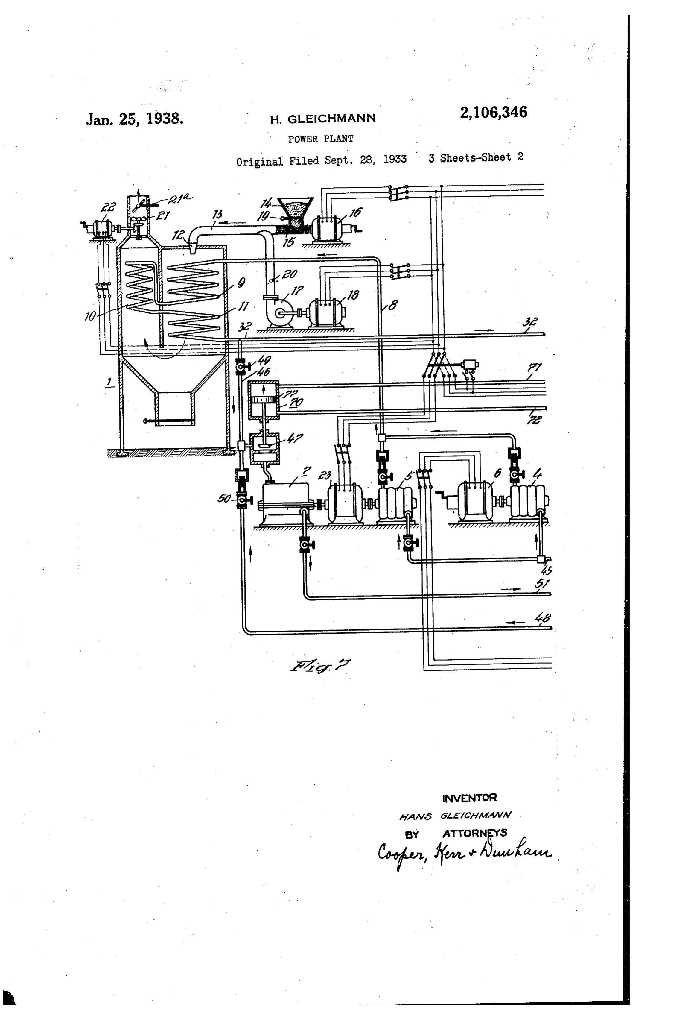
0 While the velocity of steam in the steam gen not needed operate under vacuum. erator which remains substantially constant ac of Inmythe accompanying drawings an embodiment O COrding to the above statements, the velocity of ment ofinvention is shown in which an arrange a high-pressure steam generator plant
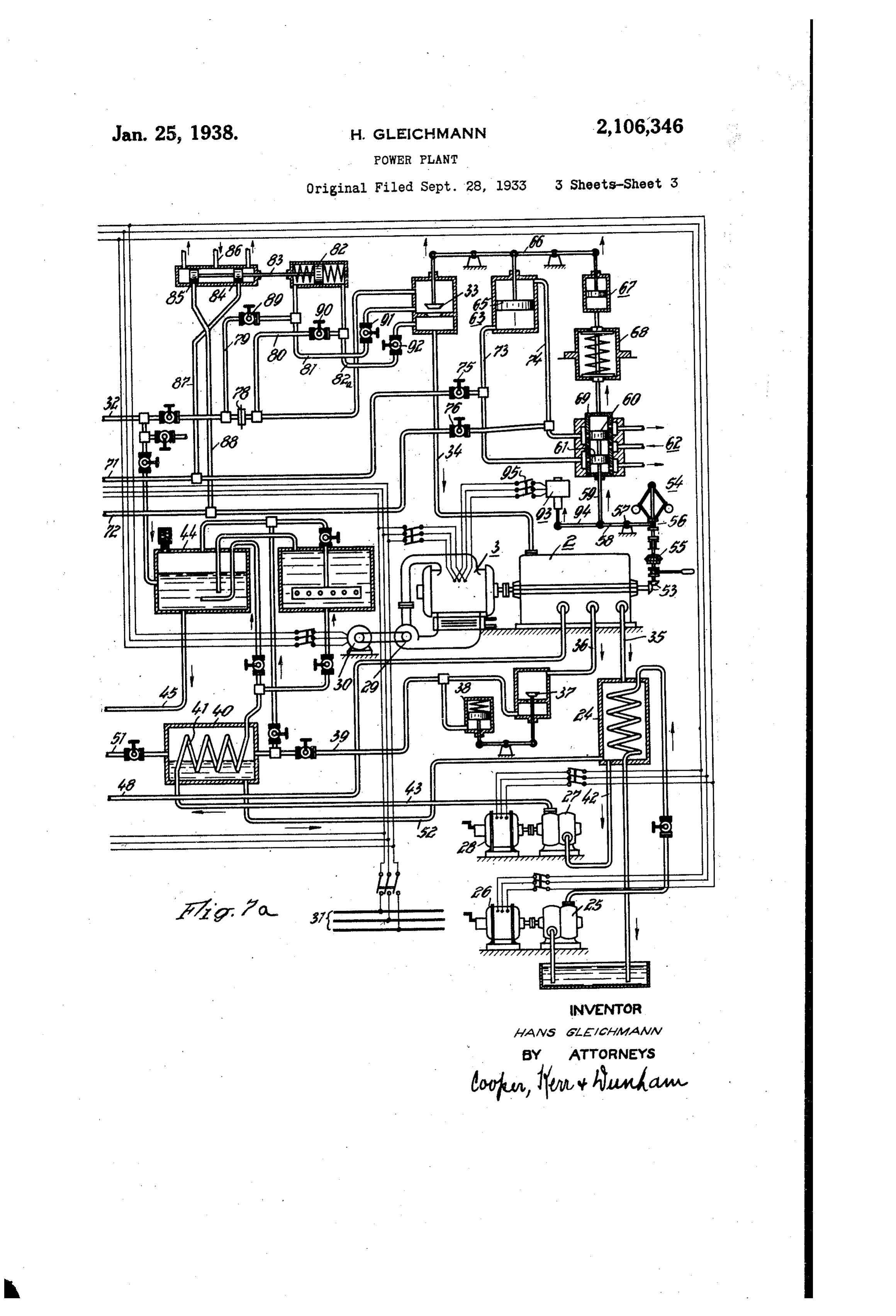
Water varies in the Water tubes in the manner is diagrammatically illustrated for carrying Out that the velocity of water decreases with de the method according to my invention. creasing load. The decrease in velocity of water The high-pressure steam generator plant Con causes according to well-known laws a decrease sists of the steam generator f, the main turbine 2, in the quantity of heat which is capable of being the main generator 3, a plurality of auxiliaries transmitted. It might occur that the Small and of the devices required for regulating the velocity of water in the case of a slight load 20 Causes a Superheating of the tubes, since the machines. Either the feed pump 4 or the feed pump 5 is employed for feeding the boiler. An
Cooling action lessens. If difficulties should arise electric motor 6 is provided for driving the feed 20 in this case the latter may be, for instance, over pump 4 and an auxiliary turbine 7 for driving come by feeding the boiler with water of dif ferent temperature; i.e., the Smaller the load the the feed pump 5. The operating medium to be evaporated is at all events forced through the lower the temperature of the water will be. The conduit 8 into the heating coil consisting of a 25 decrease in velocity of flow is thus equalized con plurality of series-connected siderably by increasing the temperature gradient, parts 9, 0, . The generatorheating surface is heated by a
So that the tubes are not stressed within undue burner fed through the conduit 3 with a mixture limits.
30 of pulverized coal and air. Pulverized coal is As to the electric machine which is driven by the turbine, one might object that such a gen supplied from the bunker 4 and forced into the 3. conduit 3, for example, by means of a worm erator Would operate unsatisfactorily, since it is conveyor too large a unit for the normal load and its eff conveyingf the 5 driven by an electric motor 6. For fuel mixture to the conduit 3 air
Ciency Would be impaired. Such an operating 3 5 condition may, however, be avoided by varying is simultaneously forced into the conduit 3 by the cooling of the generator in accordance with The means of a blower 7 driven by the motor 8. the load. The generator is designed in such a be adjustedsupplies of pulverized coal and of air may manner that it operates with the best efficiency the damper by 20, means of the register 9 and of respectively. An induced draft for the optimum load of the turbine. If the generating set should be now subjected to a is produced in the stack by a propeller 2 driven by a motor 22, a damper 2 a being arranged in 40 higher load an additional cooling will be emi the ployed, which may be brought about in different atingstack for draft regulation. Further, for Oper the plant the following auxiliaries are nec
WayS. For instance, a particular ventilator may essary: The electric motors f6, 8 and 22 are sup be installed which is put into operation only in plied with energy by an auxiliary generator 23 the case of a higher load and increases the load which is connected with the auxiliary turbine T. capacity of the generator by increasing the dis Cooling water is supplied to the condenser 24 by 45 sipation of heat from the same or which cooper ates with the auxiliary turbine in Such a manner amotorcooling water pump 25 driven by an electric 26. The condensate collecting in the COn that its power increases or decreases in accord ance with the power of the generator. How denser 24 is removed by a pump 27 driven by the ever, it is also possible to effect another kind of motor 28. Finally the blower 29 driven by the 50 motor 30 causes a circulation of the cooling air cooling which is less suitable for a continuous for operation, but which is very convenient in the and the main generator 3. The motors 26, 28 30 may also be supplied with energy by the present case since the cooling is effected by a car auxiliary rier of cold, for instance, a salt solution (brine). 6, 8, 22, generator 23. The auxiliary motors In this case the brine is cooled and stored by a current from the mainmay
generator 3 or the Supply
Small refrigerating apparatus during the period circuit 3. The motor 6 in operation is-normally of small loads. The storage of brine is simple connected to the main generator 3. It may, and economical, since it may be carried out at however, be also connected to the supply circuit 60 atmospheric pressure, by the use of an accumu 3f.
lator, that is by discharging cold brine from the 60 lower portion of the accumulator and supplying Steam is supplied to the main turbine 2 to the upper part thereof hot brine which is through the main steam conduit 32, the valve 33 Cooled in the upper portion of the accumulator and the conduit 34. The exhaust steam of the 65 by a tubular system. The cooling is normally main turbine 2 passes through the conduit 35 effected With Water in Well-known circulation into the condenser 24; it may, however, be also utilized in part for the feed water preheater.
coolers, whose output may be increased under To this-end, the main turbine 2 is branched off. circumstances in the case of increased loads by increasing the velocity of air and that of Water. The steam bled from the turbine 2 passes into 70 If this increase is not sufficient, the cooling is the feed water preheater 40 through the conduit 36 and the valve 37 which in connection with 70 brought about by brine. The cooling is, there the fore, economical, since it is only employed within duitdevice 38 maintains the pressure in the con 39 at a constant value and preheats the a fraction of the total operating period, and, consequently, requires only a small and, there feed
The water flowing through the coil 4.
condensate collecting in the condenser 24 75 fore, inexpensive cooling plant, so that the con is removed from the latter by the pump 2 75
Page 9
through the conduit 42 and forced through the tude of the main generator 3. To this end ari conduit 43 into the heating coil 4f of the pre operatedregulating electric device 93 is provided which is in response to any Suitable electrical heater 40 discharging into the collecting tank 44 characteristic, for example, voltage and its move and then either into the feed pump 4 or feed ment of adjustment is transmitted to the piston 5 pump 5 through the conduit 45 to the boiler. rod 59 through the lever 94. If the control should The auxiliary turbine 7 may either be supplied be effected from this point, the switch 95 must With Steam from the main steam conduit 32 through the conduit 46 and the regulating mem beThe closed and the coupling 55 disengaged. electric motors for driving the auxiliary ber 47 or it may also be fed with bleed steam machines are equipped with a Suitable device for 10 O from the main turbine 2 through the conduit 48. the control of their speed. In case additional Accordingly the valve 49 must be opened and impulses should be caused to act upon One or waive 50 is to be closed or reversely. The waste steam of the auxiliary turbine 7 is also Supplied more ofdevices the above-mentioned motors these ad to the feed water preheater 40 through the con justing render then possible an addition or step by step regulation. This possibility of s duit 5. The condensate collecting in the pre all heater 40 passes through the conduit 52 into the adjustment is apparent from the drawings by condenser 24 from where it is supplied into the the fact that the motors are illustrated as three generator together with condensate coming from phase commutator motors, whose brushes may the main turbine 2. be adjusted.
So long as the plant is operated with a load
Regulation of the plant is effected as follows: below
The main turbine 2 operates a centrifugal gov supplied a predetermined base load, the boiler is ernor 54 through the bevel gears 53. The gov 4. The auxiliary with feed water by the base load pump ernor is driven through a disengaging Coupling so that also the peak turbine l is then disconnected, 55. Movement of the governor sleeve 56 is trans iliary generator 23 are,load pump 5 and the aux 26 mitted to the piston rod 59 by the lever 58 pivot operation. During this consequently, put out of ally mounted, as indicated at 57. The piston rod is operated with steam of constant or turbine time the main
Substan
59 is connected to the valve of an auxiliary con
S. 62, the valve consisting of the two pistons tially constant pressure.
If the base load of the plant exceeds a certain 30
SO and 6. The adjusting device 63 for the valve value, the delivery of the feed water may be 30 33 to be regulated is controlled in the usual man either effected by the feed pump 5 only or to ner with the aid of pressure oil by means of gether with the feed pump 4. To this end the the auxiliary control 62. To attain a substan tially parallel movement of the control a dash auxiliary turbine 7 is put into operation. The steam for the auxiliary turbine may be supplied pot S, an energy absorbing device 68 and a re in this case, as above described, either from a 35 3 5 turn sleeve 69 are connected to the lever 66 oper stage of low pressure of the main turbine or from ated by the working piston 65. The valve 47 in the Steam conduit leading to the auxiliary tur the main steam pipe 32.
bine T may be controlled at the same time by The regulation of the output of the auxiliary the above described regulating device together turbine is effected at all events by the adjusting motor O. In this case the impulses of the piston 40 40 With the steam inlet member 33 of the main tur 77 of this adjusting device may either be derived bine 2. To this end an adjusting motor O is pro from the differences in pressure at the plate 78 vided for the valve 4 and connected with the or at the regulating member 33; they may, how control conduits 3 and 74 through the control ever, be also directly derived from the centrifugal conduits and T2. If the valves 75 and 76 in governor 54 through the auxiliary control 62 and 45 Serted in the conduits 7 and 2 are open, the the valves .75 and 76 or from the generator Side control impulses, which act on the piston 65, are through the regulator 93.
transmitted to the piston of the control mo The operation of plants with a load above the
prescribed
The control maybe effected in another manner, steam supply base load is characterized in that the i. e., either in accordance with differences in and in connection therewith the 50
pressure set up in operation at the plate 78 change in power occurring in the main turbine 2 is effected under a steam pressure varying with which is inserted in the main steam conduit 32 load. The higher the load above the base load, or in accordance with the difference in pres the higher the pressure will be under which the Sure resulting at the regulating member 33. The steam is forced through the turbine or reversely. differences in pressure may act on a spring In this case the power of the turbine 2 is, con biased piston 82 through the conduits 79 and 80 sequently, further regulated only by a change in or through the conduits 8 and 82a. The piston steam pressure and all delivery devices of the 82 is connected through the piston rod 83 to the plant are at the same time regulated together control pistons 84 and 85 which control the sup with the auxiliary turbine 7, since they receive 60 60 ply of oil under pressure, entering as indicated at the current from the auxiliary generator 23. A 86 to the conduits 87 and 88 and to the conduits change in Speed of the auxiliary turbine or of the and 72. If the control impulses should be auxiliary generator. 23 results, therefore, also in Caused by the differences in pressure occurring in a corresponding change in speed of the various front and behind the piate 78, the valves 89 and delivery devices. The supply of fuel, air and feed 65 65 90 are to be opened, whereas the valves 9 and 92 water as well as the speed of the motors 25, 27 are to be closed. However, if the control im and of the blower 29 is, consequently, regulated pulses are caused by the differences in pressure in front and behind the regulating member 33, at the same time within a wide range. the valves 89 and 90 are to be closed accordingly, I claim as my invention:
1. In a power plant, a prime mover, a boiler 70 70 whereas the valves 9 and 92 must be opened. supplying steam to the prime mover, heat Supply In both cases the valves 75 and 76 must be held closed. means for the boiler, feed water Supply means for Instead of influencing the auxiliary control 62 supplying water to the boiler and determining the by the centrifugal governor 54, this may be ef operating pressure, a governor operated by the 75fected in accordance with an electrical magni prime mover and controlling operation of the feed s
Page 10
water supply means so that the boiler operating istic of the load imposed on the prime mover by pressure increases with increases in prime mover the driven machine to regulate Said controlling load and vice versa, and means providing for means So as to Secure Steam pressure Which in adjustment of the heat Supply means so that creases with increase in load and vice versa, and steam having a desired temperature may be Se to increase the effectiveness of Said heat-dissipat 5 cured. ing means with increase in load and Vice versa. 2. In a power plant, a boiler of the forced 6. The combination With a turbine having a flow tubular type, a prime mover, a conduit for single and substantially invariable flow passage supplying steam from the boiler to the prime for steam, of means for varying the power de 0. mover, means for supplying media to the boiler to veloped by the turbine over a wide load range secure generation of steam under pressure Suit and including a boiler installation comprising able to the load, speed-responsive means operated forced-flow tubular heating Surface and com by the prime mover to provide a governing force, bustion means for Supplying heat thereto, a con means responsive to the governing force for duit for supplying steam from the heating Sur 5 regulating the boiler media Supply means So that face to the turbine, a feed pump for Supplying Steam is generated by the boiler at a pressure feed water to the heating surface, means for Sup dependent upon the load, a valve in said conduit plying combustion media to the combustion and which is normally nearly wide open, and means, means responsive to a load condition of means responsive to said governing force for mov the turbine for controlling the feed pump to pro 20 ing said valve. Such that, With an increase in load, vide steam pressure varying as the load, and it the valve is opened wider to provide for applica means providing for adjustment of the combus tion of reserve pressure to the prime mover to tion media supply relative to the feed water enable the latter to carry the increased load dur Supply so that steam of desired temperature may ing the interval while the pressure of steann is be be supplied to the turbine. ing changed from that suitable to the old load to 7. The combination with a multiple-stage main that Suitable to the new load, and Such that, with turbine having a single and Substantially in a decrease in load, the valve is moved in a closing variable passage for flow of steam, of means for direction to restrict the supply of steam to the varying the power developed by the main tur prime mover while the pressure of steam gen bine over a wide load range and including a arated is being decreased from that Suitable to boiler installation comprising forced-flow tubular 3:) the old load to that suitable to the new load, heating surface and combustion means for Sup whereupon, in either case, the means for moving plying heat thereto, a conduit for supplying the valve is operated in response to the then steam from the heating surface to the main tur existing governing force to restore said valve ap bine, a feed pump for supplying feed Water to proximately to its normal position. the heating surface, means for Supplying Com 3 5 3. In a power plant, a boiler of the forced-flow bustion media to the combustion means, an aux tubular type, means for operating the boiler to iliary turbine for driving the feed pump and the Secure generation of steam at variable pressure, combustion media, supply means, and means for a prime nover, a conduit for supplying steam supplying steam from an intermediate stage of from the boiler to the prime mover, a valve in the main turbine to the inlet of the auxiliary 40 Said conduit and normally partly open so that turbine.
it provides a differential pressure thereacross and 8. The combination with a multiple-stage main holds a reserve pressure of steam, which reserve turbine having a single and substantially in pressure is temporarily diminished for increasing variable passage for flow of steam, of means for 45 the power of the prime mover and which reserve varying the power developed by the main turbine pressure is temporarily increased for decreasing over a wide load range and including a boiler in the power of the prime mover incident to transi stallation comprising forced-flow. heating Surface tion from one load to another, means responsive and combustion means for supplying heat there to the differential pressure for regulating said op to, a conduit for Supplying steam from the heat erating means, and means responsive to a load ing surface to the main turbine, means for Sup effect of the prime mover to secure movement of plying feed water to the heating surface and Said valve because of load change, and later to for supplying combustion media to the combus restore it to approximately its normal position tion means, an auxiliary turbine for driving the when steam generated by the boiler has attained last-named means, and means responsive to a load SS a pressure suitable for the new load. condition of the main turbine for controlling the 55 4. In a power plant, a steam generator, means admission of steam to the auxiliary turbine. for Supplying heat and feed water to the genera 9. The combination with a multiple-stage tur tor, a prime mover supplied with steam by the bine having a single and substantially invariable generator, a condenser for condensing steam ex passage for flow of steam, of means for varying 80 hausted from the prime mover and including the power developed by the main turbine over 60 means for varying its condensing capacity, a sys tem for controlling the heat and feed water sup ation wide load range and including a boiler installa comprising heating surface and combustion ply means and the condensing-capacity-varying means So as to cause increase or decrease of the means for supplying heat thereto, a conduit for 65 rates of Supplying heat and feed water and the supplying steam from the heating surface to the (3.5 condensing capacity, and means responsive to main turbine, a feed pump for supplying feed load imposed on said prime mover for controlling water to the heating surface, means for Supply said System. ing combustion media to the combustion means, 5. In a power plant, a boiler, means for con an auxiliary turbine for driving the feed pump 70 trolling operation of the boiler to secure genera and the combustion media Supply means, means tion of Steam at variable pressure, a prime mover responsive to a load condition of the main tur supplied with steam by the boiler, a driven ma bine for controlling the admission of Steam to chine operated by the prime mover and includingthe auxiliary turbine, and means providing for heat-dissipating means whose effectiveness may the supply of combustion media to the combus 15 be varied, and means responsive to a character tion means so that steam of desired temperature
Page 11
may be supplied from the heating surface to the 13. In a power plant, a prime mover; a boiler main turbine. installation including heating Surface and COm 10. The combination with a prime mover haW bustion means for supplying heat thereto; a con ing a single and substantially invariable passage duit for supplying steam from the heating Sur 5 for flow of steam, of means for varying the power face to the prime mover; and means for Sectlr 5 developed by the prime mover over a wide load ing operation of the plant over a large power range and including a boiler installation con output range and comprising a first feed pump prising forced-flow tubular heating surface and for supplying feed-water to the heating surface combustion means for supplying heat thereto, a and determining the steam pressure, means for 10 conduit for supplying steam from the heating supplying combustion media to the Comblistion O surface to the prime mover, a feed pump for Sup means, a first motor device for operating the plying feed water to the heating surface, means first feed pump, means responsive to prime mover for supplying combustion media to the combus load demand for controlling the first motor de tion means, operating means for Said pump and vice to operate the first feed pump SO that the the combustion media Supply means, means pro boiler operating pressure increases with incrCaSe viding an orifice in said conduit, means responsive in prime mover load and vice versa, means pro to differential pressure across the orifice for con viding for adjustment of the combustion media. trolling said operating means, and means respon supplying means so that superheated Steam at sive to a load condition of the prime mover to approximately constant temperature may be Sup vary temporarily the area of the orifice so that plied to the prime mover at different outputs of said operating means may be controlled to provide the latter, a second feed pump for Supplying Water for the supply of steam from the heating Surface to said heating surface, a Second motor device to the prime mover which increases in pressure for operating the second feed pump and the com with increase in load and vice versa, and to re bustion media supply means, and means for reh 25 store approximately the normal orifice area. When dering either motor device effective So that the 25 steam is supplied at the pressure required by first motor device is effective for the upper pol the load. tion of the total range of prime mover Output 11. The combination with a prime mover hav and the second motor device is effective for the ing a single and substantially invariable passage lower portion thereof.
30 for flow of steam, of means for varying the power 14. In a power plant, a prime mover; a boiler 30 developed by the prime mover over a wide load installation including heating surface and Com range and including a boiler installation com bustion means for supplying heat thereto; a con prising forced-flow tubular heating surface and duit for supplying steam from the heating Sur combustion means for supplying heat thereto, a face to the prime mover; and means for Securing 35 conduit for supplying steam from the heating operation of the plant over a large power output 3 5 Surface to the prime mover, means for supplying range and comprising a first feed pump for Sup feed water to the heating surface and for Sup plying feed-water to the heating surface and plying combustion media to the combustion determining the steam pressure, a first motor means, means responsive to a load condition of device for driving the first feed pump, means 40 the prime mover for developing a controlling ef for supplying combustion media to the combus fect, means under control of said controlling ef tion means, means for transmitting power from fect for regulating said supply means so that the first motor device to the combustion media pressure of steam supplied from the heating Sur supply means, means responsive to prime mover face to the prime mover increases with increase load demand for controlling the first motor de 45 in load and vice versa, a valve arranged in Said vice to operate the first pump to increase the conduit and normally open to such an extent steam pressure with increases in prime mover that a relatively small pressure drop exists there load and vice versa, a second motor device for across, and means under control of Said control driving the second pump, means including a por ling effect for moving the valve, incident to load tion of said power transmitting means for trans 50 change, so that steam is applied to the prime mitting power from the second motor device to mover to meet the new load until the heating the combustion media supply means, means for surface supplies steam suitable to the new load rendering either motor device effective so that and said last-named means Operating to ap the first motor device is effective for the upper proximately restore the valve to its normal pO portion of the total range of prime mover out sition incident to the condition of the steam Sup put and the second motor device is effective for 55 ply approaching that required for the new load the lower portion thereof, and means providing condition. for adjustment of the means for supplying con 12. The combination with a prime mover hav bustion media relative to the supply of feedwater ing a single and substantially invariable passage so that steam of desired temperature may be 60 for the flow of steam, means for varying the supplied from the heating surface to the prime GO power developed by the prime mover and in OWe.
cluding a boiler installation including heating 15. In a power plant, a prime mover and means Surface and combustion means for Supplying heat for supplying to the prime mover Superheated thereto, a conduit for Supplying steam from the steam under pressure dependent upon the de 65 heating surface to the prime mover, a feed pump sired output, said means comprising a boiler for supplying feed water to the heating surface having heating surface of the series flow tubular and serving to determine the steam pressure, type, means for supplying heat to the heating means for supplying combustion media to the surface, feed water supply means for supplying combustion means, a valve in Said conduit and water to the heating surface and determining normally occupying a nearly wide-Open position, the operating pressure, means responsive to prime means responsive to differential pressure across mover load demand for controlling operation of said valve to control the feed pump such that an the feed water and of the heat Supply means SO increase in differential pressure reduces the steam that the boiler operating pressure increases with pressure and vice versa, and Speed-responsive increases in prime mover output and vice versa, 75 means for controlling said valve. and means providing for adjustment of the heat 75
Page 12
supply means independently of the feed water a feed pump for supplying water to the boiler
supply means so that steam having a desired temperature may be supplied to the prime mover and determining the operating pressure of the latter, means for supplying heat to the boiler, a at different outputs of the latter. conduit for supplying steam from the boiler to 5 16. In a power plant, a prime mover and means the prime mover, orifice means in the conduit, for Supplying to the prime mover superheated means for changing the flow area of the orifice steam under pressure dependent upon the de means, means responsive to change from a first sired output, said means comprising a boiler in load condition to a second load condition of the cluding tubular heating surface of the series flow prime mover and cooperating with the last O type, means for supplying heat to the heating surface, feedwater supply means for supplying named means to effect change in the orifice flow O Water to the heating surface and determining the area temporarily until such time as the boiler Operating pressure, a motor device operatively is Operating to supply steam to the prime mover connected to the heat supply means and to the in accordance with the second load condition, 5 feedwater supply means for operaing the latter, Said means responsive to load change operating means responsive to prime mover load demand to increase the orifice flow area because of in 5 for controlling the operation of the motor device crease in load and vice versa, and means re to secure operation of the heat supply means and sponsive to differential pressure across the ori feedwater supply means so that the boiler oper fice for controlling said feed pump so that the 20 atting pressure increases with increases in prime latter is operated to supply water to the boiler mover output and vice versa, and means provid in such manner that the operating pressure is 20 ing for adjustment of the heat supply means rela increased with increase in load and vice versa. tively to the feedwater supply means so that 21. In a power plant, a prime mover, a boiler, steam having a desired temperature may be a feed pump for supplying water to the boiler
Supplied to the prime mover at different outputs and determining the operating pressure of the of the latter. latter, combustion apparatus for Supplying heat 25
17. In a power plant, a prime mover, a boiler mediathe boiler, means for supplying combustion to the combustion apparatus, a conduit including heating surface of the series forced for supplying flow type, means for supplying heat to the heat steam from the boiler to the prime 30 mover, orifice ing surface, a feed pump for supplying water to changing the flowmeans in said conduit, means for the heating surface and determining the operat means responsive toarea of Said orifice means, 30 speed of the prime mover ing pressure, a motor device connected to the feed pump, means for transmitting power from incident a second to change from a first load condition to load condition for controlling the last the motor device to the heat supply means, a named means to effect a change in orifice flow governor operated by the prime mover and con trolling the operation of the motor device so that isarea temporarily until such time as the boiler operating in accordance with the second load the feed pump and the heat. supply means may condition when the original orifice flow area is be operated to provide boiler operating pressure approximately restored, together with restora 40 which increases with increases in prime mover tion of the Original predetermined pressure drop Output and vice versa, and means providing for over adjustment of the heat supply means relatively. beingthe orifice flow area, said orifice flow area 40 temporarily increased with increase in load to the feed pump so that steam having a desired and vice versa, means responsive to differential temperature may be supplied to the prime mover pressure across said orifice means for controlling
at different outputs of the latter. the feed pump so that the latter, is operated to 18. In a power plant, a prime mover, a boiler, supply feed. Water to the boiler in such manner 45 means for supplying media to the boiler to secure that the operating pressure of the latter is in steam generation, a conduit for supplying steam creased with increase in load and vice versa, and from the boiler to the prime mover, orifice means means providing for adjustment of said com in said conduit, means for changing the flow bustion area of said orifice means, means responsive to steam ofmedia supply means in such manner that predetermined temperature may be Sup 50 a load variation of the prime mover for control plied from the boiler to the prime mover irre ling the last-named means such that, with an spective of the Operating pressure.
increase in load, the orifice flow area is increased 22. In a power plant, a multiple-stage turbine and, with a decrease in load, the orifice flow and area is decreased, and means responsive to dif steammeans for supplying thereto superheated at a substantially constant temperature 55 ferential pressure across the orifice means for and at a pressure dependent upon the desired controlling the means for supplying media to the Output, said means and the turbine providing a boiler.
19. In a power plant, a prime mover, a boiler, substantially invariable flow passage for steam means for supplying media to the boiler to se aforsteam different outputs and said means including
cure steam generation and including a feed generator,generator, feed water heat supply means for the supply means for supply pump, a conduit for supplying steam from the ing water to the generator and determining the boiler to the prime mover, orifice means in said Operating pressure, means responsive to turbine 5 conduit, means for changing the flow area of said load demand for controlling the operation of the orifice means, means responsive to a load varia feed water supply means so that the generator 65 tion of the prime mover for controlling the last Operating pressure increases with increases intur named means such that, with an increase in bine output and vice versa, and means providing load, the orifice area is increased and vice versa, for adjustment of the heat Supply means So that () and means responsive to differential pressure superheated steam at approximately constant - across the orifice for controlling said feed pump temperature may be supplied to the turbine at 70 so that the operating pressure of the boiler is increased with increase in prime mover load different 23. The outputs of the latter.
method of developing power by means and vice versa. of a prime mover supplied with motive fluid by 75 20. In a power plant, a prime mover, a boiler, a generator which comprises supplying the nor
Page 13
tive fluid in the liquid state to the generator so superheating the vapor, and adjusting the sup that the motive fluid pressure-increases with in plies of the elements of combustion relative to creases in prime mover output and vice versa. the motive fluid supply and to each other to and supplying heat to the generator to convert maintain an approximately constant superheated the motive fluid from the liquid to the vapor vapor temperature at different prime mover out state and to superheat it to a desired tempera puts in order that the volumetric rate of flow ture in order that the volumetric rate of flow of motive fluid in the superheated vapor state of motive fluid in the superheated vapor state to to the prime mover may remain approximately the prime mover at different outputs of the lat constant.
10 ter may remain approximately constant. 26. The method of developing power by means 10 24. The method of developing power by means of a prime mover supplied with motive fluid by of a prime mover supplied with superheated a generator which comprises, up to and includ steam by a generator which comprises supplying ing a predetermined prime nover output, sup water to the generator so that the superheated plying motive fluid in the liquid state to the gen 5 Steam pressure increases with increases in prime erator at substantially a constant pressure and 5 mover output and vice versa over a pressure supplying heat to the generator to convert the range varying approximately from 35 atmos motive fudd from the liquid to the vapor state pheres to 160 atmospheres and supplying heat and to superheat the vapor and which comprises, to the generator to convert the water from the for prime mover outputs above said predeter 20 liquid to the vapor state and to superheat it tomined output, supplying the motive fluid in the 20 a temperature of the Order of 450° C. at differ liquid state to the generator so that the motive ent prime mover outputs. fluid pressure increases with increase in prime 25. The method of developing power by means mover output and vice versa and supplying heat of a prime mover supplied with motive fluid by to the generator to convert the motive fluid from 25 25 a generator which comprises supplying fuel and the liquid to the vapor state and to superheat air as elements of combustion and motive fluid it to a desired temperature in order that the in the liquid state to the generator so that the volumetric rate of flow of motive fluid in the su motive fluid pressure and the supplies of elements perheated vapor state to the prime mover at dif Of combustion increase with increases in prime ferent outputs above said predetermined output 30 hover output and vice versa, said elements of may remain approximately constant. combustion providing for conversion of motive fluid from the liquid to the vapor state and for HANS GLEICHMANN.
Provenance
- Collection
- Cited prior art
- Original PDF
- patentimages.storage.googleapis.com →
- Pages
- 13
- Method
- pdftotext (the PDF's own text layer) + pdftoppm 300dpi page scans
- Source
- Google Patents bibliographic record
- Granted
- 1938-01-25
- Transcribed from
- patentimages.storage.googleapis.com →