patent · US4426354
Power generator system for HCl reaction
17 January 1984
Page 1 — bibliographic record
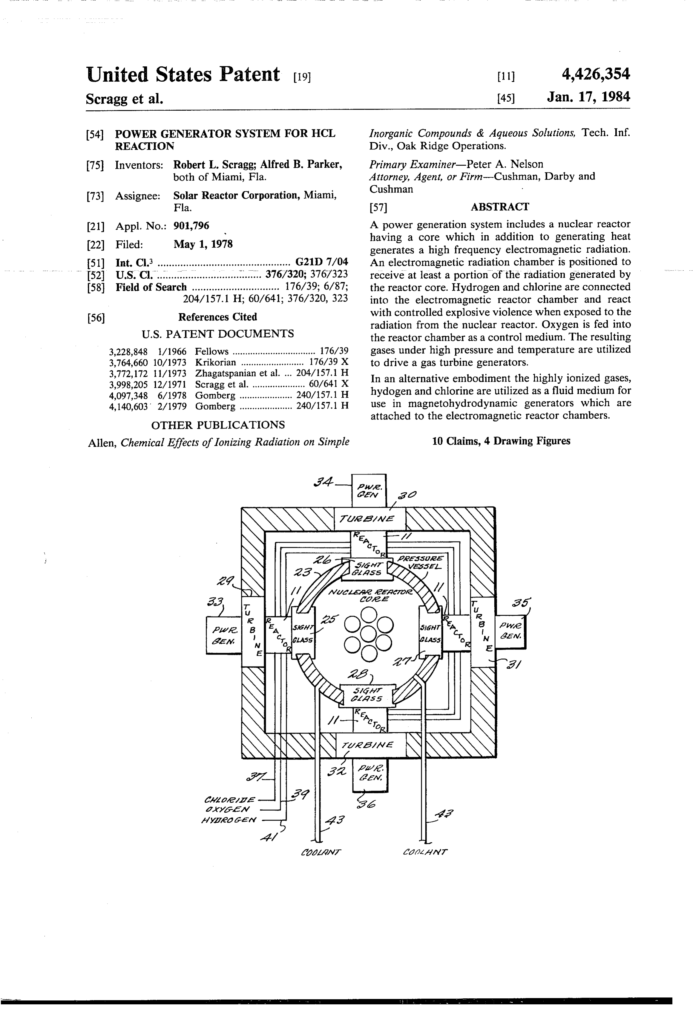
United States Patent (19) 11 4,426,354 Scragg et al. 45 Jan. 17, 1984 54) POWER GENERATOR SYSTEM FOR HCL Inorganic Compounds de Aqueous Solutions, Tech. Inf, REACTION Div., Oak Ridge Operations.
75 Inventors: Robert L. Scragg; Alfred B. Parker, Primary Examiner-Peter A. Nelson both of Miami, Fla. Attorney, Agent, or Firm-Cushman, Darby and
Cushman (73) Assignee: Solar Reactor Corporation, Miami,
Fla. (57) ABSTRACT (21) Appl. No.: 901,796 A power generation system includes a nuclear reactor (22 Filed: May 1, 1978 having a core which in addition to generating heat generates a high frequency electromagnetic radiation.
51) Int. Cl. ............................................... G21 D 7/04 An electromagnetic radiation chamber is positioned to 52 U.S. Cl............... 376/320; 376/323 receive at least a portion of the radiation generated by 58 Field of Search ............................... 176/39; 6/87; the reactor core. Hydrogen and chlorine are connected 204/157.1 H; 60/641; 376/320, 323 into the electromagnetic reactor chamber and react (56) References Cited with controlled explosive violence when exposed to the radiation from the nuclear reactor. Oxygen is fed into
3,228,848 1/1966 Fellows ................................. 176/39 gases under high pressure and temperature are utilized 3,764,660 10/1973 Krikorian ......................... 176/39 X to drive a gas turbine generators. 3,772,172 11/1973 Zhagatspanian et al. ... 204/157.1 H In an alternative embodiment the highly ionized gases, 3,998,205 12/1971 Scragg et al...................... 60/641 X 4,097,348 6/1978 Gomberg ... 240/157.1 H hydogen and chlorine are utilized as a fluid medium for 4,140,603 2/1979 Gomberg ....... ... 240/157.1 H use in magnetohydrodynamic generators which are attached to the electromagnetic reactor chambers.
OTHER PUBLICATIONS
Allen, Chemical Effects of Ionizing Radiation on Simple 10 Claims, 4 Drawing Figures
Page 2
Drawing sheet — no readable text.
Page 3
Drawing sheet — no readable text.
Page 4
Drawing sheet — no readable text.
Page 5
POWER GENERATOR SYSTEM FOR HCL BRIEF DESCRIPTION OF THE DRAWINGS REACTION Other objects, features and advantages of the present invention will become more fully apparent from the
BACKGROUND OF THE INVENTION 5 following detailed description of the preferred embodi This application is related to copending U.S. patent ment, theinappended claims and the accompanying application Ser. No. 857,895 filed Dec. 6, 1977, which in drawings which:
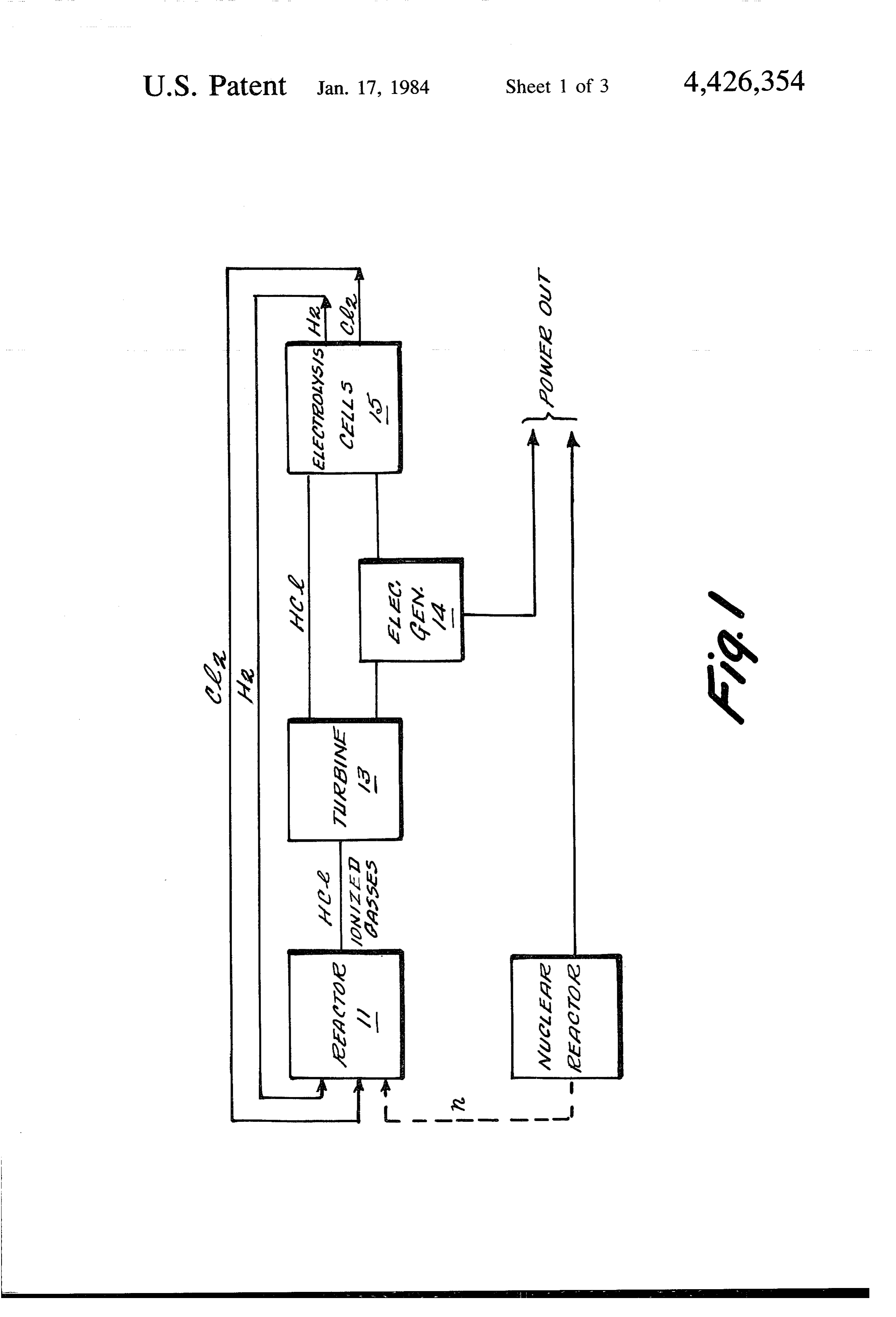
FIG. 1 is a schematic block diagram of the preferred turn is a continuation-in-part of U.S. patent application
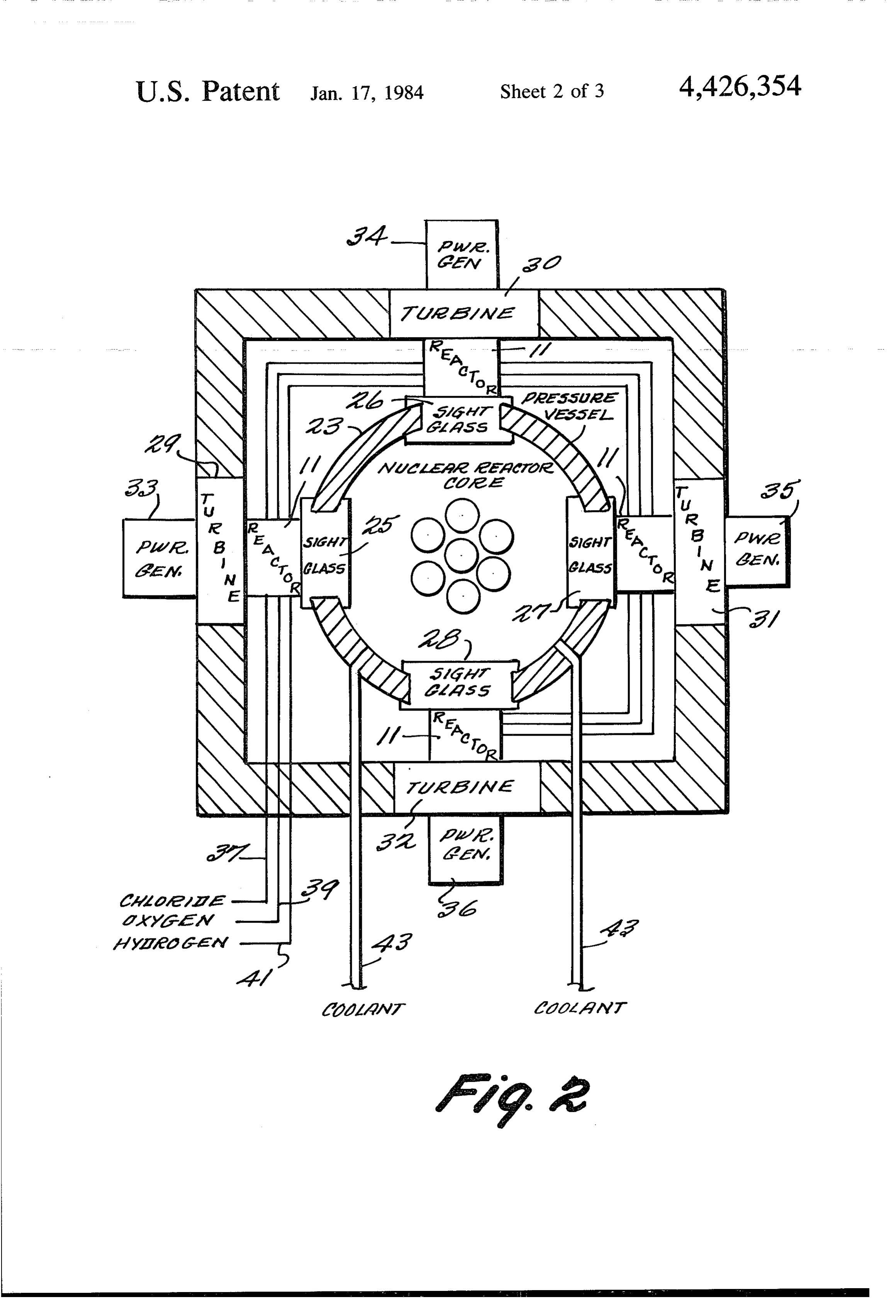
Ser. No. 692,495 now U.S. Pat. No. 4,070,861, which in 10 embodiment of the present invention; FIG. 2 is a simplified section view of the preferred turn is a continuation-in-part of U.S. patent application
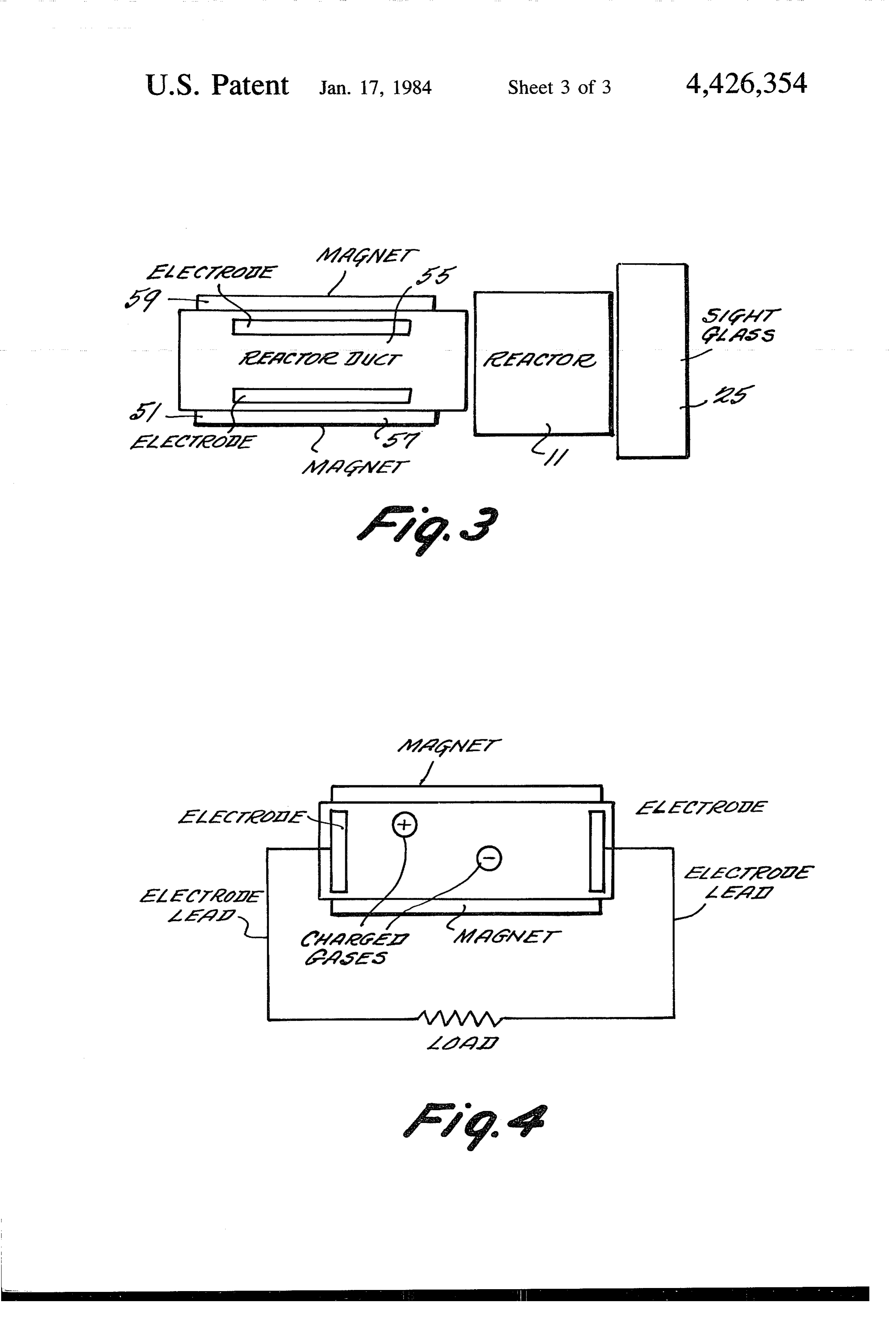
Ser. No. 657,383 now U.S. Pat. No. 4,026,112, which in embodiment of the present invention; turn is a continuation-in-part of U.S. patent application FIG. 3 is a simplified schematic block diagram of the Ser. No. 588,888 now U.S. Pat. No. 4,024,715, which in power generation system of the present invention turn is a continuation-in-part of U.S. patent application 15 wherein the output of the reactor drives a magnetohy drodynamic generator; and
This invention relates to a system for converting FIG. 4 is a simplified schematic diagram of a magne ... electromagnetic energy to mechanical energy. - tohydrodynamic generator.
As disclosed in the aforementioned U.S. patents, it is DETAILED DESCRIPTION OF THE known to convey controlled amounts of hydrogen and 20 PREFERRED EMBODIMENT chlorine to a chamber which is exposed to high fre quency electromagnetic radiation such as derived from Refer now to FIG. 1 which is a simplified schematic the sun or from an artificial light source. The chlorine illustration of the preferred embodiment of the present molecules are broken up into atomic chlorine with some invention. An electromagnetic reactor chamber 11 of chlorine being ionized. The atomized chlorine combines 25 the type illustrated and described in U.S. Pat. Nos. with hydrogen atoms to form hydrogen chloride. The 4,070,861; 4,026,112; 4,024,715 and 3,998,205 each of hydrogen chloride is formed in an exothermic reaction which are assigned to the common assignee herewith, is which results in the temperature of the hydrogen chlo shown having its output connected to a turbine 13. As ride being substantially higher than that of the chlorine will be explained more fully hereinbelow the reactor or hydrogen molecules conveyed to the reactor cham generates high temperature, high pressure hydrogen ber. The resulting high temperature, high pressure gas is chloride and highly ionized hydrogen and chlorine. utilized to drive an output device such as a turbine. These gases are coupled to a turbine 13 which is de Such a system requires a substantial amount of high signed to withstand the highly corrosive hydrogen energy electromagnetic radiation. This is not available chloride and which converts the high energy molecules from the sun unless a concentrator is utilized. Further, 35 and particles from reactor 11 to mechanical energy. The even with a concentrator, the sunlight is not continu output of the turbine drives a suitable power output ously available and the level of sunlight changes with device such as an electrical generator 14. The gases the seasons and with the weather. from the turbine which include hydrogen chloride are Thus there is a need in the art to provide an improved coupled to an electroylsis cell 15 which through a pro source of high energy electromagnetic radiation. 40 cess of electrolysis commonly known in the art gener It is also known in the art to provide a nuclear reactor ates molecular hydrogen and chlorine. The molecular for converting nuclear into mechanical or electrical hydrogen and chlorine are controllably coupled back to energy. A number of different types of reactors are the reactor 11 to form the reactants therein. available, however, all reactors generate high fre As an important part of the present invention, a nu quency radiation including gamma rays. This radiation 45 clear reactor 17 of conventional design has a nuclear which is harmful to humans is dissipated through a reactor core therein, together with nuclear fuel rods, shield. This energy is thus lost during the nuclear power moderator rods and control rod piles, each of which are generation process. contained in a pressure vessel. The pressure vessel has There, accordingly, is a need in the art to provide an at least one sight glass in the vessel wall in close proxim improved means for utilizing the high energy radiation 50 ity to the reactor 11. The nuclear reactor produces generated in nuclear reactors. thermal and radiant energy as nuclear transition and
SHORT STATEMENT OF THE INVENTION
degradation occurs within the reactor 17. Gamma rays from the reactor are directed into the reactor chamber
Accordingly, this invention relates to an energy con 11 and absorbed by the chlorine and hydrogen mole version system which includes an electromagnetic reac 55 cules in the presence of oxygen. The resulting highly tor chamber having inputs for controllably coupling energized gases generate light, heat and pressure in the chlorine and hydrogen thereto. The chamber is posi reactor 11. The high pressure gases in turn drive the tioned with respect to a nuclear reactor such that high turbine 13. The gases and gamma radiation are quantita energy radiation from the reactor is conveyed from the tively controlled to bring about the desired reaction nuclear reactor to the electromagnetic reactor chamber. 60 between the reactants for the purpose of obtaining the The radiation from the nuclear reactor is, therefore, desired energy levels for the turbine 13. utilized to convert the hydrogen and chlorine to hydro The thermal energy from the nuclear reactor 17 may gen chloride and other highly charged particles at high be utilized to drive the same power output device as temperature and pressure levels. Thus a continuous driven by the reactor 11 or may be used for any other source of high energy radiation is provided while at the 65 suitable purpose.
same time a means is provided for eliminating the dan Refer now to FIG. 2 which is a simplified section ger of harmful radiation leaking from the nuclear reac view of the referred embodiment of the present inven tor. tion.
Page 6
As illustrated in FIG. 2, a nuclear reactor power ber, the desired energy levels can be achieved for driv Svstem is illustrated in simplified plan view and includes ing the respective turbines.
reactor housing 21 which is formed of reinforced Refer now to FIGS. 3 and 4 which are simplified oncrete or other materials capable of retaining high schematic block diagrams of the power generation sys frequency radiation. The housing 21 contains a nuclear tem of the present invention wherein the output of the reactor core which is positioned within a pressure ves electromagnetic reactor drives a magnetohydrody sel 23. The pressure vessel has, in the preferred embodi namic generator. In this embodiment of the invention of ment, a plurality of sight glasses 25-28 which are sup the chlorine and hydrogen gases in the electromagnetic ported and fixed in the pressure vessel at appropriate reactor chamber are highly ionized and the resulting intervals about the wall. The sight glasses must be 10 charged particles are utilized as a medium for the mag strong enough to support the pressure generated by the netohydrodynamic (MHD) generators 51 that may be nuclear reactor core while at the same time be transpar positioned in place of the gas turbines of FIG. 2, or in ent to the high frequency electromagnetic radiation the alternative may be positioned at the output of the generated therein. gas turbines to receive whatever ionized gases are A plurality of electromagnetic reactor chambers 11 15 passed through the turbine. As is known in the art the are each positioned proximate a sight glass for receiving ionized hydrogen and chlorine atoms resulting from the the high frequency electromagnetic radiation generated absorption of gamma and alpha radiation by the chlo in the core. The electromagnetic reactor chambers, as rine and hydrogen are expanded into a reactor duct 55 aforementioned, are of the type disclosed in the afore 20 which is in the middle of a magnetic field produced by mentioned U.S. patents, the subject matter of which is electromagnets 57 and 59. Electrodes 61 and 63 posi incorporated herein by reference thereto. The reactor tioned inside and insulated from the wall of the reactor chambers are each secured to a corresponding sight duct 55 receive the charged particles as they are de glass by suitable mechanical means to render the cham flected to the respective electrodes by the electromag bers pressure tight at the junction of the sight glass and 25 netic field generated by the magnets. Thus a positive the reactor. Secured to the other end of the reactors are potential is generated at one electrode and a negative turbines 29-32. Preferably the turbines 29-32 are se potential at the other electrode thereby causing the cured to and supported by the nuclear reactor housing generation of current. The output from the reactor duct 2 turbines as illustrated. The turbines may be of any may then be utilized by coupling the gases to a suitable suitable degree known in the art. However, the turbine 30 storage or conversion units for converting the gases to must be capable of withstanding the corrosive effects of molecular hydrogen chlorine for feeding back to the hydrogen chloride and highly ionized gases. The tur reactor chamber in the manner described in connection bines are each connected directly to an electric power with FIG. 1.
generator 33-36. The output of the power generators It should be understood by those skilled in the art that can be utilized for any suitable purpose. 35 while a preferred embodiment has been disclosed in A chlorine conduit 37, an oxygen conduit 39 and a connection with the present invention there may be hydrogen conduit 4 are coupled to each of the reactor other embodiments which fall within the spirit and chambers with the hydrogen and chlorine providing the scope of the invention as defined by the appended reactants in the electromagnetic reactor chambers and claims.
the oxygen being utilized as a control medium. In addi 40 We clain:
tion, as is known in the art, coolant conductors 43 are 1. A energy generation system comprising coupled to the nuclear reactor core to carry away there a reactor chamber, from the heat energy generated in the core. means for controllably coupling chlorine and hydro In operation, in the preferred embodiment, a coolant gen to said reactor chamber, is circulated through the pipes 43 for the purpose of 45 a nuclear reactor core, removing heat from the reactor core with the heat from a housing for said nuclear reactor core, said housing the core being utilized to generate steam directly or via being capable of withstanding the pressure gener a suitable heat exchanger for the purpose of providing a ated inside thereof, said nuclear reactor core gener means for driving steam turbine generators. In addition, ating high frequency electromagnetic radiation, the nuclear reactor produces thermal and electromag 50 means for directing at least a portion of said electro netic energy during the nuclear transition and degrada magnetic radiation into said reactor chamber, to tion within the core. As nuclear transformation and thereby exothermically react said hydrogen and degradation occur, gamma radiation is reduced and chlorine to generate highly charged particles and alpha radiation increased. At least in part of this electro hydrogen chloride, said highly charged particles magnetic radiation is conducted through the sight 55 and hydrogen chloride having a high temperature, glasses into each of the electromagnetic reactor cham and bers. At the same time hydrogen and chlorine gas are means for converting at least some of the energy of controllably fed into the reactor chambers together said generated hydrogen chloride and highly with oxygen. The high energy electromagnetic radia charged particles to mechanical energy. tion is absorbed by the chlorine and hydrogen mole 60 2. An energy conversion system comprising cules in the presence of the oxygen. The resulting an electromagnetic reactor chamber, highly energized gases form hydrogen chloride as well means for controllably coupling chlorine and hydro as highly ionized chlorine and hydrogen. These highly gen to said reactor chamber, energized gases generate heat and pressure in each of a nuclear reactor, said nuclear reactor including a the reactors which energy is utilized to drive the respec 65 core for generating high frequency electromag tive turbines. By controlling the input of hydrogen and netic radiation and a pressure vessel, said nuclear chlorine as well as oxygen or by controlling the amount reactor core being positioned inside of said pres of high energy radiation coupled to the reactor cham sure vessel,
Page 7
means for directing at least a portion of said high 5. The energy conversion system of claim 4, wherein frequency electromagnetic radiation generated by said means for converting the energy of said highly said nuclear reactor core into said electromagnetic ionized hydrogen and chlorine to electrical energy reactor chamber, said electromagnetic radiation comprises a magnetohydrodynamic generator, and being absorbed by said hydrogen and chlorine to 5 means for conducting said highly ionized hydrogen thereby generate high energy hydrogen chloride, and chlorine into said generator, said generator highly ionized hydrogen and chlorine generating an electrical current. means for controlling the rate of generation of said 6. The energy conversion system of claim 5, wherein hydrogen chloride, ionized hydrogen and chlorine, said magnetohydrodynamic generator includes means and 10 for generating an electromagnetic field, a reactor duct, means for converting the energy of said hydrogen said electromagnetic field passing through said reactor chloride, ionized hydrogen and chlorine to me duct, said means for conducting said ionized hydrogen chanical energy. and chlorine to said reactor duct and a pair of electrodes 3. An energy conversion system comprising in said reactor duct for receiving the charge of said an electromagnetic reactor chamber, 15 ionized hydrogen and chlorine when deflected by said means for controllably coupling chlorine, hydrogen electromagnetic field.
and oxygen to said reactor chamber, 7. A power generation system comprising a nuclear reactor, said nuclear reactor including a a reactor chamber, - core for generating high frequency electromag means for controllably coupling chlorine hydrogen netic radiation and a pressure vessel, said nuclear 20 and oxygen to said reactor chamber, reactor core being positioned inside of said pres a nuclear reactor core, sure vessel a housing for said nuclear reactor core, said housing means for directing at least a portion of said high being capable of withstanding the pressure gener frequency electromagnetic radiation generated by ated inside thereof, said nuclear reactor core gener said nuclear reactor core into said electromagnetic 25 ating high frequency electromagnetic radiation, reactor chamber, said electromagnetic radiation means for directing at least a portion of said electro being absorbed by said hydrogen and chlorine to magnetic radiation into said reactor chamber, to thereby generate high energy hydrogen chloride, thereby exothermically react said hydrogen and said hydrogen chloride having a high temperature, chlorine to generate highly charged particles and and 30 hydrogen chloride, said highly charged particles means for converting the energy of said high temper and hydrogen chloride having a high temperature, ature hydrogen chloride to mechanical energy. a turbine, 4. An energy conversion system comprising means for coupling said hydrogen chloride and an electromagnetic reactor chamber, highly charged particles to said turbine. means for controllably coupling chlorine and hydro-35 8. The power generation system of claim 7, further gen to said reactor chamber, comprising means for converting said hydrogen chlo a nuclear reactor, said nuclear reactor including a ride to molecular hydrogen and chlorine, and core for generating high frequency electromag means for coupling said hydrogen and chlorine to netic radiation and a pressure vessel, said nuclear said means for controllably coupling chlorine and reactor core being positioned inside said pressure 40 hydrogen to said reactor chamber. vessel, 9. The power generation system of claim 8, further means for directing at least a portion of said high comprising means connected to said turbine for con frequency electromagnetic radiation generated by verting said highly charged particles to an electric cur said nuclear reactor core into said electromagnetic rent.
reactor chamber, said electromagnetic radiation 45 10. The power generation system of claim 1, wherein being absorbed by said hydrogen and chlorine to said means for converting the energy of said highly thereby generate high frequency hydrogen chlo charged particles and hydrogen chloride to mechanical ride, highly ionized hydrogen and chlorine, power is connected to the output of said nuclear reac means for converting the energy of said highly ion tor. ck Sk k k k ized hydrogen and chlorine to electrical energy. 50
Provenance
- Collection
- Cited prior art
- Original PDF
- patentimages.storage.googleapis.com →
- Filed
- 1978-05-01
- Pages
- 7
- Method
- pdftotext (the PDF's own text layer) + pdftoppm 300dpi page scans
- Source
- Google Patents bibliographic record
- Granted
- 1984-01-17
- Inventors
- Robert L. Scragg; Alfred B. Parker; Solar Reactor Corp
- Transcribed from
- patentimages.storage.googleapis.com →