patent · US4356812
Directional solar heating assembly
2 November 1982
Page 1 — bibliographic record
United States Patent 19 11 4,356,812 Haven 45) Nov. 2, 1982 (54) DIRECTIONAL SOLAR HEATING transparent enclosure for exposure to the rays of the ASSEMBLY sun. The transparent enclosure is adjacent the reflecting 76 Inventor: Robert M. Haven, 204 E. Emma, surface of a reflector for focusing the rays of the sun on Lafayette, Colo. 80026 the fluid receiver. An insulated door is pivotally con nected to the thermally insulated compartment and is 21 Appl. No.: 340,998 movable between a position permitting communication (22 Filed: Jan. 20, 1982 between the thermally insulated compartment and the 51) Int. Cl’................................................. F24, 3/O2 transparent enclosure and a position thermally sealing 52 U.S. C. .................................... 126/438; 126/419; the insulated compartment. The receiver engages the 126/443; 126/422; 126/425; 126/428; 126/435 insulated door for pivoting the door open as the re 58 Field of Search ............... 126/438, 439, 420, 443, ceiver moves from the insulated compartment to the 126/418, 419, 422,423, 424, 425, 428,429, 435, transparent enclosure, and a cable guided by a series of 437, DIG. 1; 136/246, 251 pulleys connects the receiver to the door for closing the
door as the receiver moves from the transparent enclo sure to the insulated compartment. A thermally actu
229,109 6/1880 Ely .................................. 26/439 X ent enclosure unless the ambient temperature falls 528,255 10/1894 Monks et al. . below a predetermined level. A tilting mechanism tilts 4,022,188 5/1977 Cohen et al. ........................ 126/27 the reflector about a horizontal axis to follow the rise 4,088,116 5/1978 Pastor .................................. 26/270 and fall of the sun, and a turntable for rotating the re 4,192,291 3/1980 Arent .................................. 126/439 ceiver and reflector follows the travel of the sun across Primary Examiner-Samuel Scott the sky and cooperates with the tilting mechanism in Assistant Examiner-Randall L. Green tilting the reflector. A season adjustment mechanism is Attorney, Agent, or Firm-Lane, Aitken, Kice & associated with the tilting mechanism to provide differ Kananen ent degrees of tilting for different seasons.
A solar heating assembly includes a fluid receiver mov able between a thermally insulated compartment and a 21 Claims, 8 Drawing Figures
s Azatterit
Page 2
Drawing sheet — no readable text.
Page 3
Drawing sheet — no readable text.
Page 4
Drawing sheet — no readable text.
Page 5
Drawing sheet — no readable text.
Page 6
and out of the way and establishing communication
DIRECTIONAL SOLAR HEATING ASSEMBLY between the insulated compartment and the transparent enclosure.
BACKGROUND OF THE INVENTION A thermally actuated release retains the receiver in An ample supply of hot water has long been an indis the transparent enclosure and permits the receiver to pensable need for residential and commercial uses. roll down the inclined rails from the transparent enclo Since the cost of energy has risen dramatically in recent sure to the insulated compartment in response to the years, it has become increasingly desirable to find an temperature of the ambient air falling below a predeter economical but effective way of heating water. mined value. In addition, the solar collector is rotatably Various devices have been proposed to fill the need 10 mounted on a base in order to follow the travel of the for supplying economical hot water. However, these sun across the sky, and a tilting mechanism tilts the devices have had shortcomings of one type or another. reflector up and down about the horizontal shaft in For example, some devices continue to use fossil fuels, response to the rotation of the solar collector on the electricity, or other forms of energy which are rela 15 base, so that the reflector follows the rise and fall of the tively expensive and which continue to increase in cost. sun with respect to the horizon. The tilting mechanism Furthermore, such forms of energy require some sort of includes a season adjustment to provide different de transmission lines or other type of transportation to grees of tilt to account for the different paths taken by convey them to the point of use. In other devices, the sun in different seasons.
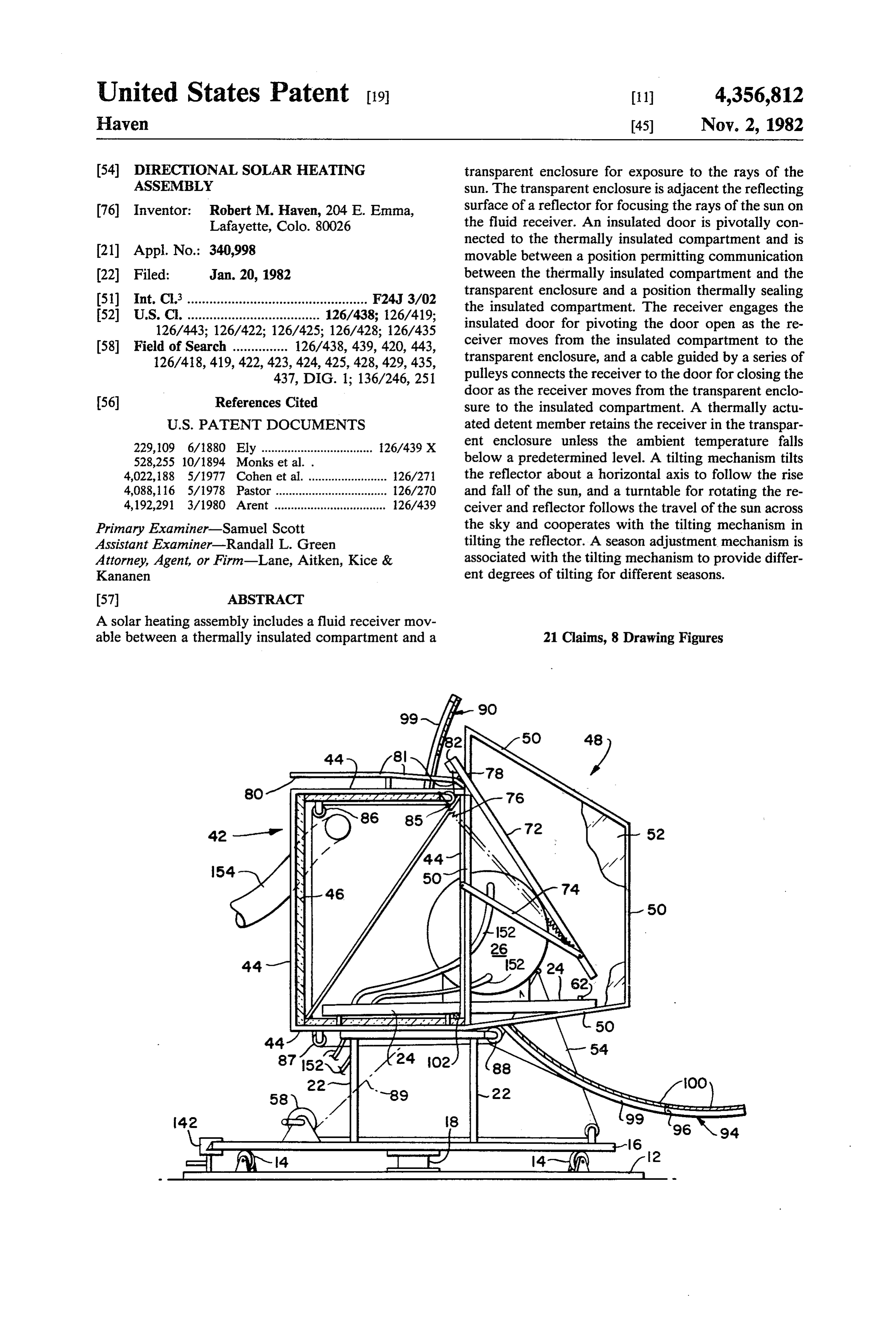
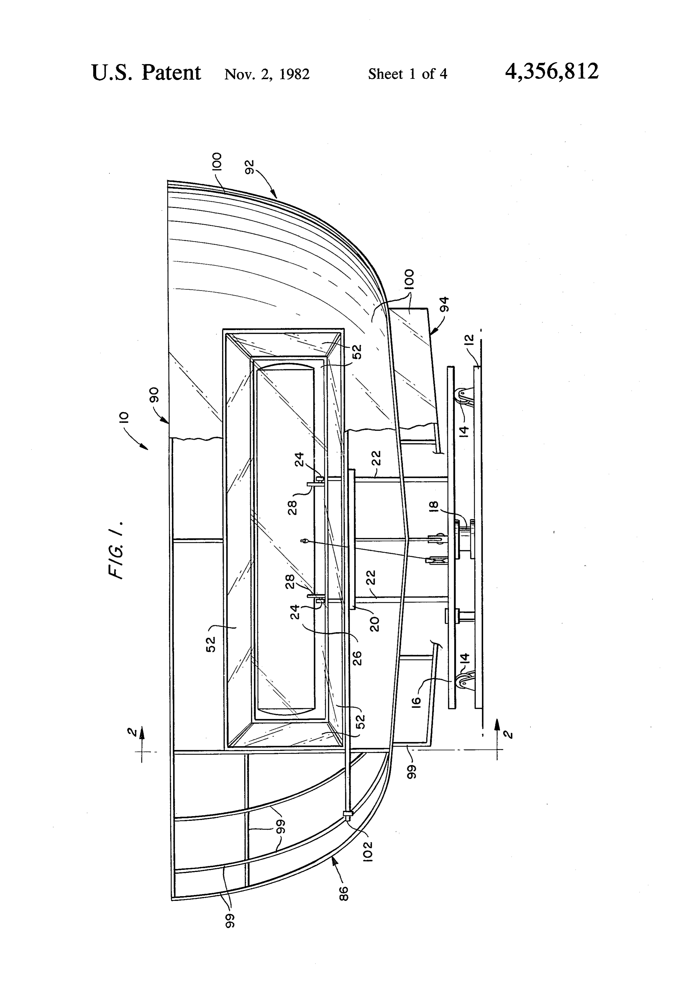
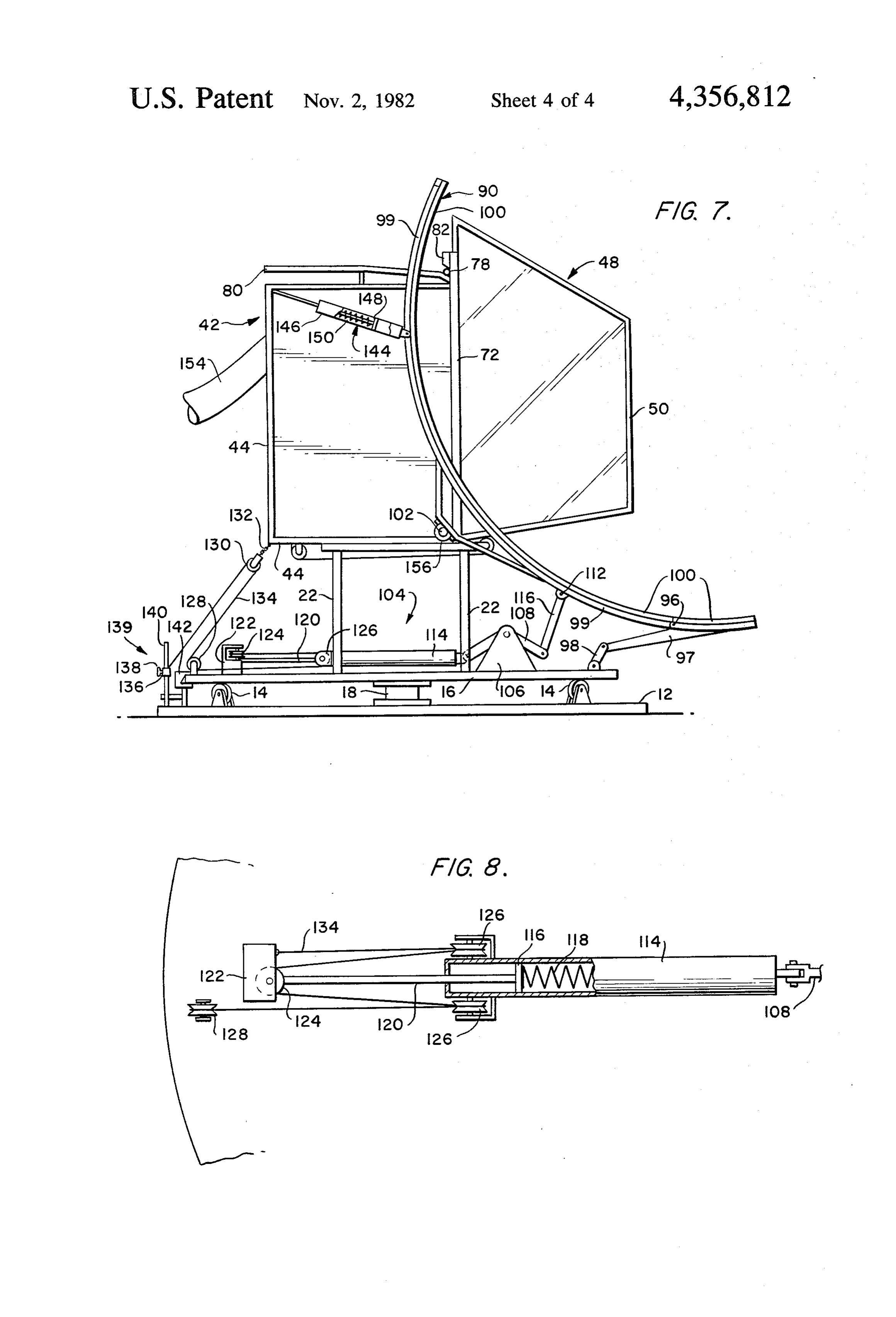
which employ free energy such as solar energy, the devices have either been ineffective to supply the neces 20 BRIEF DESCRIPTION OF THE DRAWINGS sary heat to the water or other fluids to be heated, or FIG. 1 is a front elevational view of the solar collec have been so large, complex or costly as to make their tor assembly according to the present invention, cut use impractical. Still other devices fail to provide a away on one side to show the frame;
system for retaining the heat once it has been collected FIG. 2 is a cross-sectional view of the solar collector or fail to provide their components with adequate pro 25 assembly, taken along line 2-2 in FIG. 1, showing the tection from the elements, especially from freezing receiver in the insulated compartment;
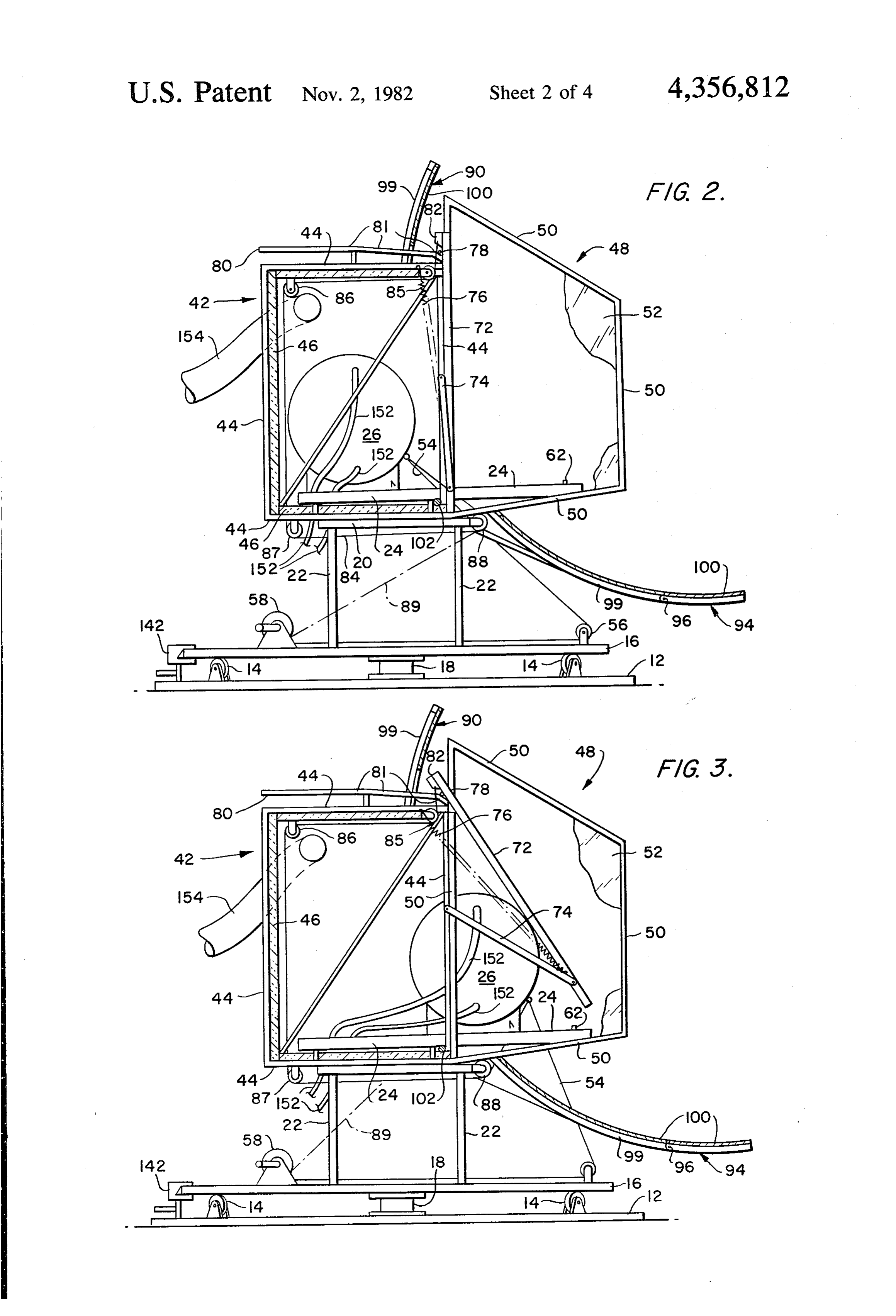
weather. FIG. 3 is a cross-sectional view similar to FIG. 2, but SUMMARY OF THE INVENTION showing the receiver between the insulated compart It is, therefore, an object of the present invention to 30 ment and the transparent enclosure; provide a solar heating assembly which is relatively showing thea receiver
FIG. 4 is cross-sectional view similar to FIG. 2, but in the transparent enclosure;
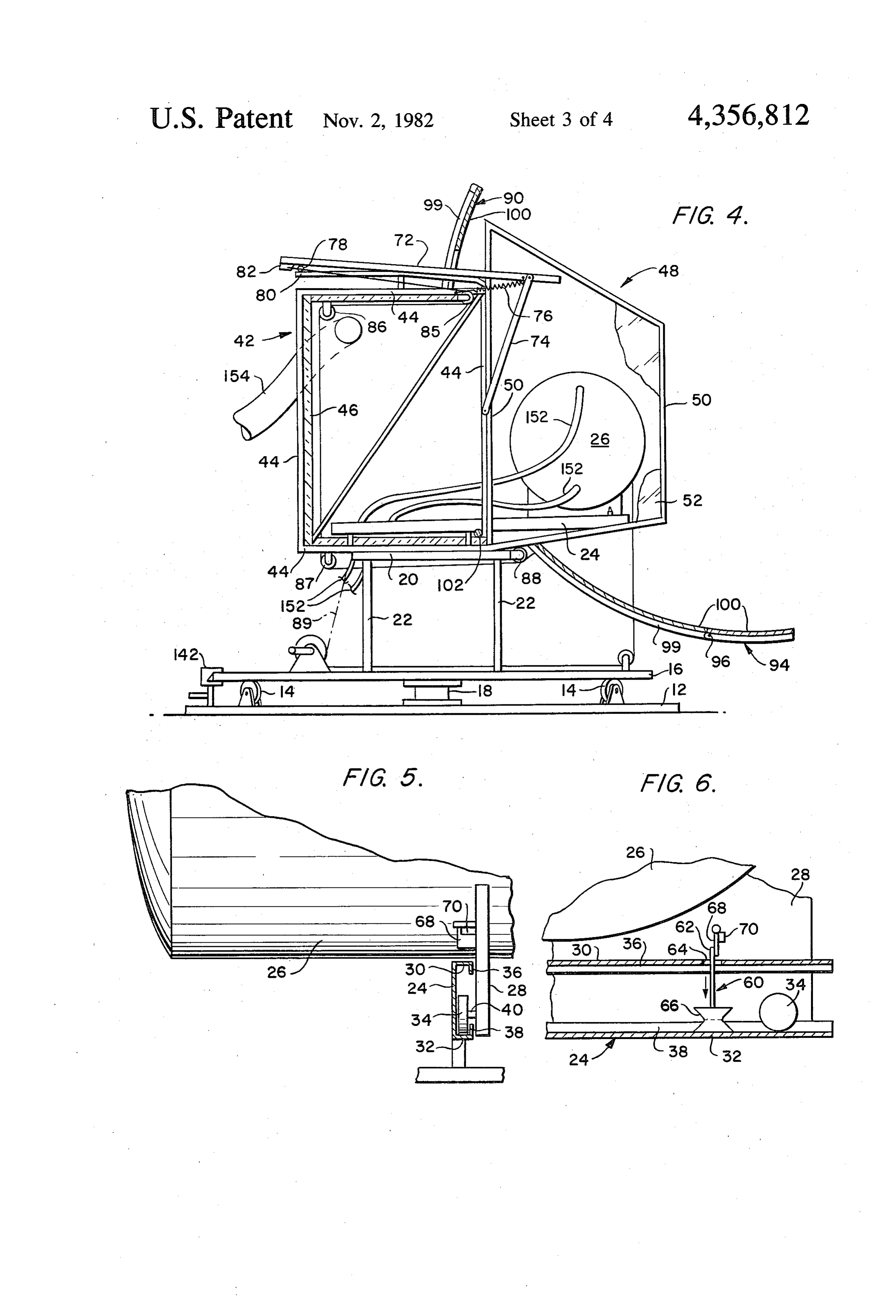
simple and inexpensive to produce, but which is effec FIG. 5 is an enlarged front elevation of a portion of tive in maximizing the energy of the sun to heat water the receiver, showing the cooperation between the or some other heat transfer medium.
It is another object of the present invention to pro 35 receiver support and the rail; vide a solar heating assembly which tracks the move showing FIG. 6 is an enlarged cross section of one of the rails, ment of the sun in order to collect the most intense the temperature-responsive release mecha available solar energy at all times of the day and in all nism; FIG. 7 is a side elevational view of the solar collector SeaSOS,
It is still another object of the present invention to assembly, showing the tilting mechanism; and FIG. 8 is a plan view of a portion of the tilting mecha provide a solar heating assembly having a thermally insulated compartment to retain, in a heat transfer me nism of FIG. 7.
dium, the heat collected from the sun. DETAILED DESCRIPTION OF THE It is yet another object of the present invention to PREFERRED EMBODIMENT provide a solar heating assembly having a mechanism to 45 protect from freezing the portions of the assembly car As is illustrated in FIG. 1, the solar heating assembly rying water or other heat transfer medium. according to the present invention, which is generally Toward the fulfillment of these and other objects, the designated by the reference numeral 10, includes a base solar heating assembly according to the present inven 12 having a plurality of rollers 14 mounted on an upper tion comprises a solar collector including a heat transfer 50 surface in a circular pattern to engage and support a fluid receiver or tank movable between a transparent lower surface of a turntable 16 which is rotatably con enclosure through which the rays of the sun are col nected to the base 12 by a shaft 18. A platform 20 is lected to heat the fluid and a thermally insulated con supported above the turntable 16 by legs 22 which are partment in which the heat of the fluid is retained dur connected to the platform and affixed to the turntable. ing periods when solar energy is not being collected. A 55 A pair of channel members serving as rails 24 are parabolic reflector is pivotally mounted with respect to mounted in parallel on the platform 20 and extend be the transparent enclosure about a horizontal shaft, curv yond the platform 20 in the front and the rear. The rails ing around the transparent enclosure so that the trans 24 are inclined downward from front to rear for reasons parent enclosure is in the focal area of the reflector. The to be described hereinafter.
receiver is mounted on rollers which move along in A fluid receiving tank or receiver 26 for holding a clined rails between the insulated compartment and the heat transfer medium such as water is positioned across transparent enclosure. A cable is connected to the re the rails 24 and is supported for rolling along the rails. ceiver and wound around a winch to pull the receiver The fluid receiver 26 has supports which include a pair toward the transparent enclosure. An insulated door, of U-shaped cradle members 28 welded or otherwise which separates the insulated compartment from the 65 suitably secured to the underside of the fluid receiver transparent enclosure, is contacted by the receiver as 26. As is best illustrated in FIG. 5, in which the left rail the receiver moves from the insulated compartment to 24 is shown, the channels which are defined by the rails the transparent enclosure, thereby pivoting the door up 24 face one another and have upper and lower flanges
Page 7
30 and 32, respectively, the lower flanges 32 defining occurs, the thermally responsive bellows 66 contracts surfaces on which rollers 34 mounted on the U-shaped and moves the detent member 62 down and out of en members cradle 28 may travel. A short vertical flange gagement the tab 68. As a result, the fluid receiver 26 36 depends from the upper flange 30 and another short rolls down the rails 24 into the insulated storage com vertical flange 38 extends up from the lower flange 32 partment 42, where it is protected from freezing. to define a slot extending the length of the rail 24. The As shown in FIG. 2, when the receiver 26 is in the rollers 34 are mounted on stub shafts 40 extending from insulated compartment 42, an insulated door or parti the outer sides of the U-shaped cradle members 28, so tion 72 is movable between a position in which it per that the rollers 34 are received in the channels defined mits communication between the insulated storage com by the rails 24, and the stub shafts 40 are accommodated 10 partment 42 and the transparent enclosure 48, and a by the slots between the vertical flanges 36 and 38. position in which it separates the insulated storage com Since the rails 24 are inclined, the fluid receiver 26 will partment 42 from the transparent enclosure 48 and aids roll to the lower ends of the rails. in thermally sealing the insulated compartment 42 from As is illustrated in FIGS. 2-4, a thermally insulated the ambient air. The door 72 is pivotally mounted by compartment 42 comprising a frame of lightweight 15 links 74 to generally vertical frame members 44 on the structural members 44 and panels 46 of thermal insula forward side of the insulated compartment 42. The links tion is mounted on a rear portion of the platform 20, 74 have first ends pivotally mounted to the generally from which it extends beyond the platform 20 and be vertical frame members 44 and extend downwardly to a yond the lower ends of the rails 24. The structural men pivotal connection between their other ends and lower bers 44 can be tubular aluminum or other lightweight 20 portions of the sides of the insulated door 72. Elongated structural material, and the panels 46 can include any spring devices 76, such as coil springs, one of which is suitable thermal insulation, such as fiberglass. shown, extend from an upper horizontal frame member A transparent enclosure 48 is mounted on a forward 44 to a point of attachment near the pivotal attachment portion of the platform 20 in communication with the of the link 74 with the door 72. The door 72 includes a insulated compartment 42, extending beyond the front 25 roller 78 mounted near each side, protruding rear and sides of the platform 20 and beyond the upper ends wardly from a portion of a door 72 extending above the of the rails 24. The transparent enclosure 48 includes a insulated compartment 42. A pair of tracks 80 are sup frame of tubular aluminum or other lightweight mem ported in parallel relationship on the top of the insulated bers 50 and panels 52 of glass or other transparent mate compartment 42 in alignment with the rollers 78, the rial. Since the insulated compartment 42 and the trans tracks 80 including a plurality of sections 81 which parent enclosure 48 are in communication, the fluid slope downwardly toward the front of the insulated receiver 26 can roll from the insulated compartment 42 compartment 42 at slightly increasing angles. to the transparent enclosure 48. In order to move the As is shown in FIG. 3, the door 72 is opened by fluid receiver 26 up the rails 24 from the insulated com engagement with the fluid receiver 26 as the receiver is partment 42 to the transparent enclosure 48, a cable 54 35 pulled forward from the insulated compartment 42 to is attached to the fluid receiver 26 or to one of the the transparent enclosure 48. The surface of the fluid U-shaped cradle members 28, from which it extends receiver 26 engages the door 72 and causes it to move forward and downward around a pulley 56 mounted forward and upward by means of the pivoting of the near the forward periphery of the turntable 16. The links 74. As the pivoting motion takes place, the upper cable 54 is then wound around a winch 58 which is also portion of the door 72 is supported on the tracks 80 by mounted on the turntable 16. The winch 58 may be the rollers 78, which move along the tracks from front power driven or may include a hand crank for manual to rear. The elongated spring devices 76 are under ten operation. sion when the door 72 is closed, and the tension in A thermally actuated release mechanism 60, as is creases as the door 72 pivots open until the spring de shown in FIG. 6, comprises a catch or detent member 45 vices 76 pass by the pivotal connection between the link 62 extending from an upper portion of one of the rails 24 74 and the generally vertical structural member 44. to protrude through an aperture 64 formed in the upper. After this point in the travel of the door 72, the spring flange 30. The catch or detent member 62 is mounted on devices 76 contract, pulling the door upward and rear the top of a thermally responsive bellows 66, mounted ward. A counterweight 82 mounted at the top of the within the rail 24, which expands with increasing tem 50 door 72 aids in keeping the top of the door down on the perature and contracts with decreasing temperature. In tracks 80 as the lower portion of the door pivots up normal ambient operating temperatures, the detent ward.
member 62 engages a tab 68 pivotally mounted on the The door 72 is automatically closed when the re adjacent cradle member 28. The tab 68 is capable of ceiver 26 rolls into the insulated compartment 42 by a freely swinging to the rear, so that it can pass by the 55 cable 84 which is secured at one end to the counter detent member 62 when the receiver 26 is moved into weight 82 or a region of the door 72 near the counter the transparent enclosure 48. However, a stationary weight and at the other end to the receiver 26. The member 70 affixed to the cradle member 28 just forward cable is guided by a plurality of pulleys 85,86, 87 and 88 of the tab 68 prevents the tab 68 from pivoting forward which are mounted on or near the insulated compart past the vertical. Thus, in normal operating tempera 60 ment 42. Thus, as the receiver 26 rolls down the rails 24 tures, the tab 68 engages the forward side of the detent into the insulated compartment 42, it pulls the cable 84 member 62 and prevents the receiver 26 from rolling around the pulleys 85-88, which in turn pulls the door back down the rails 24, thereby retaining the receiver in 72 forward along the tracks 80 and down through the the transparent enclosure 48. action of the links 74. The door 72 is then pulled tightly The catch or detent member 62 remains in its pro 65 shut by the force of the spring devices 76. truding position, and, thus, retains the receiver 26 in the As an alternative to the cable 54 wound around the transparent enclosure 48 unless the temperature of the pulley 56 to move the fluid receiver 26 into the transpar ambient air falls below a predetermined value. If this ent enclosure 48, the cable 54 and the pulley 56 can be
Page 8
eliminated in favor of a cable 89 connected to the cable the other pulley 126 of the pair of pulleys, under the 84 between the pulleys 87 and 88 and wound around the pulley 128 and over the pulley 130. The free end of he winch 58, as is shown by the broken lines in FIGS. 2-4. cable 134 is secured to a selectively movable element, Although a pivoting door has been described, it is un such as a collar 136 having a thumb screw 138, of a derstood that other insulated doors or partitions may be season adjustment mechanism 139 which also includes a employed. stationary element, such as a rod 140, with respect to A large reflector 90 is pivotally mounted on the plat which the selectively movable element is adjustable. form 20 and has a reflecting surface curving around the The stationary element is preferably mounted at the transparent enclosure 48, which is positioned on the side rear of the base 12.
of the reflector 90 having the reflecting surface. The O With the reflector 90 facing south, the cylinder 114 is reflector 90 includes a parabolic section 92 adjacent in a forward position with respect to the piston 116, and each end of transparent enclosure 48, so that the trans the reflector is tilted back to its greatest extent, as illus parent enclosure is approximately at the focal point of trated in FIGS. 7 and 8, so that it will be aimed at the each parabolic section 92. The reflector 90 also includes sun when the sun is at its zenith. Rotation of the turnta a hinged forward section 94 extending approximately 15 ble 16 in either direction away from its south orientation the width of the transparent enclosure 48 and connected causes the collar 136 to pull on the cable 134, thereby by a removable hinge pin 96 to the remainder of the moving the cylinder 114 rearward with respect to the reflector 90 at the forward bottom edge. As can be seen piston 116. The rearward movement of the cylinder 114 from FIG.7, the hinged forward section 94 includes a forces the rear lever arm of the lever 108 to move up depending web 97 connected to the turntable 16 by a and the forward lever arm to move down, tilting the link 98, which is pivotally attached at one end to the reflector 90 forward and down. Thus, the reflector 90 is web 97 and at the other end to an element secured to the tilted up to its maximum inclination at the center of its turntable 16. The depending web 97 and the link 98 arc of rotation about the base 12 and is tilted down to its have been omitted from the other drawing figures for minimum inclination at the beginning and end of its arc. the sake of clarity of illustration. 25 Thus, in operation, the reflector 90 begins tilted down at The reflector 90 comprises a frame made from light one end of its arc to aim at the rising sun. Then, as the weight structural members 99 such as tubular aluminum reflector 90 is rotated about its arc, it tilts up to a maxi members and panels 100 each having a reflecting sur mum inclination at about noon and tilts back down as it face for receiving sunlight and reflecting it toward the tracks the sun to sunset.
fluid receiver 26. The entire reflector 90 is pivotally 30 Since the sun will attain greater height in the sky in mounted about a horizontal shaft 102 secured to the the summer than in the winter, the season adjustment forward portion of the platform 20, below the parallel mechanism permits the reflector 90 to be tilted higher in rails 24. the summer than in the winter. To move from a winter As can be seen from FIG. 7, the reflector 90 is tilted setting to a summer setting, the selectively movable about the horizontal shaft 102 by a tilting mechanism 35 element of the season adjustment mechanism, such as generally designated by the reference numeral 104. Like the collar 136, is moved up along the stationary ele the web 97 and the link 98, the tilting mechanism 104 ment, such as the rod 140, and secured there. This has been omitted from the other drawing figures for movement permits the cylinder 114 move farther for clarity. The tilting mechanism 104 includes a support ward and the reflector 90 to tilt higher for each angular member 106 mounted on the turntable 16 for supporting 40 position of the reflector 90 in its arc. a lever 108. The lever 108 is pivotally mounted at its The turntable 16 can be manually rotated on the base center to the support member 106, thereby defining a 12 to follow the movement of the sun across the sky. As forward lever arm and a rear lever arm. The front end an alternative, a photoelectric detector can be mounted of the forward lever arm is pivotally connected to one on the turntable 16 and can be connected to an electrical end of a link 110 whose other end is pivotally connected 45 drive mechanism to rotate the turntable 16 until the to a lower portion of the reflector 90 by an element 112, reflector 90 is precisely directed toward the sun. Other which is attached to the reflector 90 between the hinge suitable automatic devices can be utilized. Where the 96 and the horizontal shaft 102. turntable 16 is rotated manually, a caliper brake 142 is The rear lever arm of the lever 108 is pivotally con mounted on the base 12 and is foot-operated to engage nected to the forward end of a horizontally oriented 50 the turntable 16. Furthermore, the release for the brake cylinder 114 which contains a piston 116 and a spring 142 is also foot-operated.
118 which biases the cylinder 114 forward with respect A pair of stabilizers 144, one of which is shown in to the piston 116, as can be seen from FIG.8. The piston FIG. 7, are connected between the frame of the reflec 116 is secured to a piston rod 120 which extends tor 90 and the frame of the insulated compartment 42 to through the rear of the cylinder 114 for attachment to 55 stabilize the reflector 90 and damp its movements in an anchor member 122 mounted on the rear of the turn heavy winds, while permitting relative movement be table 16 for rotatably supporting a pulley 124 having a tween the reflector 90 and the insulated compartment vertical axis. A pair of pulleys 126 having a horizontal 42 as the reflector pivots about the horizontal shaft 102. axis is mounted on the cylinder 114, one of said pulleys Each stabilizer 144 includes a pneumatic cylinder 146 126 positioned on each side of the cylinder 114 at its 60 connected to one frame, a piston 148 connected to the rear. Another pulley 128 having a horizontal axis of other frame and receivable in the cylinder 146, and a rotation is mounted at the rear of the turntable 16 adja spring 150 mounted in the cylinder 146 and biasing the cent to the anchor member 122, and yet another pulley piston 148 to its fully telescoped position. Thus, the 130 is suspended by a short length of cable or chain 132 springs 150 assist in pulling the reflector 90 up and back, from the insulated compartment 42. 65 after it has been pulled down and forward by the cable A cable 134 is secured to the anchor member 122 and 134. It can be seen from FIGS. 2-4 that the fluid re is fed under the pulley 126 on the side of the cylinder ceiver 26 has outlets and fittings to which hoses 152 114 opposite the pulley 128, around the pulley 124, over may be connected to supply relatively cold water to the
Page 9
fluid receiver and to remove heated water therefrom. 4. The solar heating assembly of claim 3 further in The hoses 152 extend through apertures in the bottom cluding means for tilting the reflector about a horizontal insulated panel 46 of the insulated compartment 42 and axis to follow the rise and fall of the sun. lead to the point of use. For example, the hoses 152 can 5. The solar heating assembly of claim 4 wherein the be connected to the inlet and outlet of a conventional tilting means comprises hot water tank to provide a domestic or commercial a cylinder, supply of hot water. As an alternative, the hoses 152 can a mechanical linkage connecting the cylinder to the be connected directly to an apparatus employing the reflector, hot water, such as a clothes washer or dishwasher. In 10 a piston slidable in the cylinder, and addition, the air in the insulated compartment 42 be means for moving the cylinder with respect to the pis comes very hot and dry due to the heated fluid in the ton, whereby the mechanical linkage tilts the reflec receiver 26 when the receiver 26 with its heated fluid is tor about a horizontal axis. positioned therein and also due to the heat from the sun 6. The solar heating assembly of claim 5 wherein the which flows into the insulated compartment when the 15 means for moving the cylinder comprises: insulated door 72 is open. Thus, a flexible conduit 154 spring means biasing the piston toward one end of the cylinder, can be provided to extend from the thermally insulated compartment 42 to provide a supply of hot, dry air for a piston rod connecting the piston to an anchor member a number of uses, such as drying clothes. For such a mounted on the turntable, purpose, the conduit 154 can be connected directly to 20 a stationary element mounted on the supporting surface, the inlet of a clothes dryer. pulleys associated with the anchor member and with the The entire solar heating assembly 10 can be disassem cylinder, and bled into three parts for relatively easy movement and a cable secured with respect to the turntable at one end, shipping. The hinged forward section 94 can be re guided around the pulleys and connected at its other moved from the rest of the reflector 90 due to the re 25 end to the stationary element, whereby, upon rotation movable hinge pin 96 and the fact that the pivotal con of the turntable, the cable moves the cylinder on the nection of the depending web 97 with the link 98 is piston against the bias of the spring means and causes removable. The remaining portion of the reflector 90 is the mechanical linkage to tilt the reflector about a removable from the rest of the solar heating assembly horizontal axis.
10 due to the mounting of the reflector 90 about the cluding 7. The solar heating assembly of claim 4 further in horizontal shaft 102 by brackets 156 (FIG. 7) which are adjustingmeans, the tilt associated with the tilting means, for of the reflector for different seasons.
held together by bolts or other removable fasteners. 8. The solar heating assembly of claim 6 wherein the The ability of the solar heating assembly 10 to be disas cable sembled into three parts significantly reduces the over tivelyismovable connected to the stationary element by a selec element, which, by its movement, ad
all dimensions of the assembly and its awkwardness for justs the tilting of moving and shipping. the reflector for different seasons. 9. The solar heating
Although the foregoing describes certain preferred reflector includes at least assembly of claim wherein the embodiments of the solar heating assembly according to having the transparent enclosure a pair of parabolic sections the present invention, it is understood that various 40 focal points. in the region of their changes and modifications may be made without de 10. The solar heating assembly of claim 1 wherein the parting from the spirit and scope of the present inven insulated door is pivotally mounted between the trans tion as recited in the appended claims and their legal parent enclosure and the thermally insulated compart equivalents. ment, and the receiver engages the insulated door, so What is claimed is:
45 that, as the receiver moves from the thermally insulated 1. A solar heating assembly, including a solar collec compartment to the transparent enclosure, it causes the tor comprising: insulated door to pivot from the thermally sealing posi a receiver for holding a heat transfer medium, tion to the position permitting communication between a reflector having a reflecting surface, the thermally insulated compartment and the transpar a transparent enclosure mounted on the solar collector 50 ent enclosure.
on the side of the reflector having the reflecting sur 11. The solar heating assembly of claim 10 wherein face, spring means are connected to the insulated door to an insulated storage compartment mounted on the solar assist the receiver in moving the insulated door to the collector, the thermally insulated compartment being position permitting communication between the ther in communication with the transparent enclosure, 55 mally insulated compartment and the transparent enclo an insulated door movable from a position permitting Sute.
communication between the thermally insulated 12. The solar heating assembly of claim 1 wherein the compartment and the transparent enclosure to a posi receiver is positioned on a supporting surface extending tion thermally sealing the thermally insulated com from the thermally insulated compartment to the trans partment, and parent enclosure, and the means for moving the re means for moving the receiver between the thermally ceiver includes roiler means connected to the receiver insulated compartment and the transparent enclosure. and movable on the supporting surface.
2. The solar heating assembly of claim 1 further in 13. The solar heating assembly of claim 12 wherein cluding means for rotating the solar collector to follow the supporting surface is sloped upwardly from the the sun. 65 thermally insulated compartment to the transparent 3. The solar heating assembly of claim 2 wherein the enclosure.
rotating means includes a turntable rotatably mounted 14. The solar heating assembly of claim 13 wherein to a supporting surface. the supporting surface comprises parallel rails.
Page 10
15. The solar heating assembly of claim 1 wherein the transparent enclosure to the thermally insulated com solar collector further includes means for retaining the partment.
receiver in the transparent enclosure. 18. The solar heating assembly of claim 1 further 16. The solar heating assembly of claim 15 wherein comprising conduits connected to the receiver for sup plying and drawing off the heat transfer medium.
the retaining means includes thermally actuated release 19. The solar heating assembly of claim 1 further means for allowing the receiver to move from the trans comprising a conduit connected to the thermally insu parent enclosure to the thermally insulated compart lated compartment for drawing off heated air from the ent. thermally insulated compartment. 20. The solar heating assembly of claim 1 wherein the 17. The solar heating assembly of claim 1 wherein the 10 reflector includes a forward section pivotally connected receiver is connected to the insulated door by a cable to the rest of the reflector.
for moving the insulated door from the position permit 21. The solar heating assembly of claim 1 further ting communication between the thermally insulated comprising stabilizer means for damping the movement compartment and the transparent enclosure to the ther 15 of the reflector.
mally sealing position as the receiver moves from the it is
Provenance
- Collection
- Cited prior art
- Original PDF
- patentimages.storage.googleapis.com →
- Filed
- 1982-01-20
- Pages
- 10
- Method
- pdftotext (the PDF's own text layer) + pdftoppm 300dpi page scans
- Source
- Google Patents bibliographic record
- Granted
- 1982-11-02
- Inventors
- Robert M. Haven
- Transcribed from
- patentimages.storage.googleapis.com →