patent · US3457020
Direct ignition of fluid fuel burners
22 July 1969
Page 1
Drawing sheet — no readable text.
Page 2
United States Patent Office 3,457,020 Patented July 22, 1969
3,457,020 opened with the relay energized, the fuel valve coil is DERECT IGNITION OF FLUD FUEL BURNERS energized to open the fuel valve. If the fuel is ignited, Louis P. Hine, Jr., Elyria, Ohio, assignor to Luxaire, Inc., the sensor contacts will remain closed by radiation from Elyria, Ohio, a corporation. of Delaware the burning fuel but if after a short time, the fuel is not Filed Dec. 7, 1967, Ser. No. 688,715 ignited, the glow wire will have cooled sufficiently to re Int, CI. F23n 5/02, F23q, 2/28 close the sensor contacts thus deenergizing the fuel valve U.S. C. 431-66 4 Claims coil to close the valve. Thereafter, when the igniter wire again glows to a level sufficient to reopen the sensor con tacts, the cycle will repeat until fuel ignition is obtained.
ABSTRACT OF THE DISCLOSURE 0 Failure of the electric supply causes the valve to close; This invention relates to fluid fuel burners and an elec if the sensor contacts fail closed the valve cannot open; trical ignition system therefor that is directly energized if the flame goes out the valve is closed; and if the Sensor upon the need for heat to ignite the fuel without the use contacts fail open before ignition, the glow wire cannot of continuously operating pilot flames or the like charac glow or the relay cannot energize and therefor the igni tion system of the invention is effectively fail-safe. Fur terized by a heat sensitive switch which in the cold condi 5 ther tion is closed shorting the gas supply valve operator, but features and advantages of the invention will be ap when heated by an electrical resistance igniter or by an parent with reference to the following specification and established flame is open thus removing the short. drawings in which:
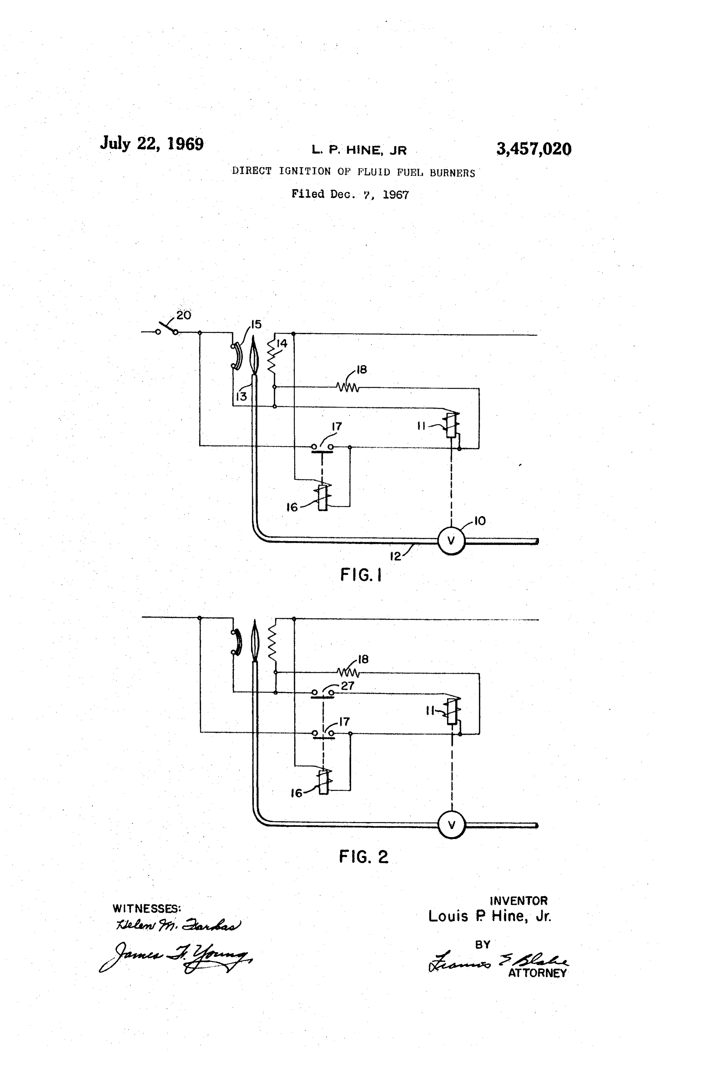
FIGURE 1 is a wiring diagram of the preferred em 20 bodiment of the invention; and
CROSS REFERENCES TO RELATED FIG. 2 is a wiring diagram of a slightly modified form APPLICATIONS of the invention.
So far as is known, this application is not related to DESCRIPTION OF THE PREFERRED any other copending patent applications. EMBODIMENT BACKGROUND OF THE INVENTION Referring to FIGURE 1 of the drawings, the wiring diagram for the direct electrical ignition system of the
Fluid fuel burners and particularly gas fueled burners invention will now be described. An electrically controlled and furnaces have mostly employed continuously burning fluid pilot flames for their ignition systems because of the 30 in thefuel fuel valve 10 having an operating coil 11 is connected line 12 extending to the burner jet 13. An elec safety features that have been provided for such systems. trical resistance glow igniting wire 14 is positioned in However, provided that equivalent or better safety fea proximity to the fuel jet 13 so as to ignite fluid fuel by tures can be obtained, a direct ignition system without the radiation emitted from the glow wire 14 when it is continuously burning pilot frames would be more advan heated. A radiation sensing switch 15 having normally tageous under many conditions of operation. Recent elec 35 closed contacts is also positioned to respond to radia trical developments in radiation sensing switches have tion emitted by the direct ignition glow wire 14 when it is encouraged the development and application of a glow heated sufficiently to cause ignition of the fuel flowing wire type of direct ignition system having the desired from the burner jet 13. A relay switch having a coil 16 safety features of closing the fuel valve when ignition is and a set of normally open contacts 17 is provided with not obtained or when the flame goes out. It may also be 40 its coil connected in a series operating circuit including desirable to provide a direct ignition system with means the fixed voltage dropping resistor 18 in series with the to cycle the fuel valve from open to closed position if the normally closed radiation sensor contacts 15. With this fuel fails to ignite after a short period of time and to arrangement, upon the closure of the thermostat or main thereafter again cycle on the glow wire ignition element so that the valve and ignition element may alternately cycle 45 switch 20 to the source of electric current, the glow wire 14 will be energized through the normally closed radiation off and on until fuel ignition does take place. sensor switch 15 and the control relay coil 16 will also be PRIOR ART energized simultaneously therewith. The normally open
United States Reissue Patent 25,976 is typical of the circuit relay contacts 17 are thereby closed to provide a holding prior art patents relating to a glow wire type of direct so that the relay coil 16 will remain energized after ignition system for fluid fuel burners and this patent is 50 the normally closed radiation sensor switch 15 is opened classified in class 431 subclass 31 of the United States subsequent to the detection of sufficient radiation energy patent classification. from the igniter wire 14 for igniting the fluid fuel. SUMMARY It will be noted that electric valve coil 11 is connected through the operated contacts 17 of the relay 16 in a cir
In accordance with the invention, a direct ignition sys 55 cuit that is in parallel with the normally closed sensor tem for fluid fuel burners having the above-described ob Switch 15 so that the fluid valve coil 11 will not be ener jects and advantages is obtained with the use of a radia gized until the normally closed sensor switch 15 is opened tion sensing switch having normally closed contacts con upon detection of the requisite level of radiant energy nected in a series circuit with a resistance glow wire to a from the glow wire 14. After sufficient radiant energy for source of electric current. A relay switch and coil with a ignition is being generated by the glow wire 14 to cause set of normally open contacts is provided with its coil con 60 the sensor switch 15 to open, the valve coil 11 will be nected in series with a voltage dropping resistance in a energized in series with the igniter wire 14 to open the circuit in parallel with the glow wire so that the relay coil valve 10 and pass fluid fuel to the burner jet 13. There is first energized simultaneously with the energization of after the fuel valve 11 remains open in series with the the glow wire. The relay contacts are connected in a series 65 igniter wire 14 which continues to pass current, although holding circuit with the relay coil to the source of current with the valve coil 11 in series therewith, the energy so that the relay will remain energized after the radiation through the glow wire 14 is insufficient to maintain it in sensing contacts are opened for deenergizing the glow a glowing condition. However this arrangement assures wire after the glow wire is emitting sufficient radiation for that should the glow wire break to open the series circuit ignition of the fuel. An electric fuel valve is connected 70 to the fuel valve coil 11, the valve will be closed. in series with the relay contacts in a circuit in parallel with Assuming that the glow wire 14 has heated sufficiently the sensor contacts So that after the sensor contacts are to emit radiation for igniting fuel from the fuel jet 13
Page 3
and the sensor switch 15 is thereby opened, should the mined level of radation is sensed, an electrical resistance fuel fail to ignite within a reasonable short period of time, glow wire adapted to emit radiation in proximity to fuel the cooling of the glow wire 14 that is then connected released by said valve, a relay switch and coil having a in series with the valve coil 11, will cause the radiation set of normally open contacts to be closed when its coil sensor switch 15 to reclose to again short circuit the oper 5 is energized, means connecting said glow wire and sensor ating coil 11 of the valve 10 and close the valve 10 and contacts in series to a source of electric current for ener again pass full electrical current through the glow wire 14 gizing said glow wire, means connecting said relay coil to reheat the wire to ignition temperature. Thus the igni in series with a voltage dropping resistance in a parallel tion wire 14 and the fuel valve coil 11 are alternately circuit to said wire whereby said relay coil is energized energized in cycles until ignition is obtained but the fuel 10 with said glow wire, means connecting the coil of said valve 10 is not kept open for any sufficient period of time valve in series with said relay contacts to said source in to cause unsafe amounts of gas to be released without a parallel circuit to said normally closed contacts, and ignition. If the sensor contacts should fail closed, the fuel means connecting said relay coil in a series holding circuit valve coil 11 will remain shorted at all times and it will with its normally open contacts to said source whereby the be impossible to open the fuel valve. Should the igniter 15 coil of said valve is energized to open the valve when said wire fail open the fuel valve 11 will close since its oper sensor contacts are opened upon detection of radiation ating circuit is extended through the igniter wire 14. from said wire and is maintained energized so long as said Referring now to FIGURE 2 of the drawings, a slightly sensor contacts remain open upon detection of radiation modified form of the invention is shown in which the con from ignited fuel with said relay coil remaining energized trol relay is provided with a second set of normally open 20 through its holding circuit.
contacts 27 which are connected in the series circuit 2. The invention of claim 1 in which the series circuit through the coil 1 of the fuel valve 10. This arrange of the fuel valve coil and normally open relay contacts ment is somewhat more complicated than that described is connected in series with said glow wire to said source in FIGURE 1 in view of the provision of the second set of current.
of normally open contacts for the control relay but may 3. The invention of claim 1 in which said relay switch have some advantage where the relative values of the fixed is provided with a second set of normally open contacts, voltage dropping resistance 18 together with the resistance said second set of contacts being connected in series with of the fuel valve operating coil 11 and the relay operating said valve coil to form a series circuit in parallel with coil 16 are not precisely predetermined. It should be appar 30 said dropping resistance when said second set of contacts ent that the fuel valve operating coil 11 cannot be ener are closed.
gized until after the relay coil 16 has been energized to 4. The invention of claim 2 in which said relay switch close its normally open contacts. 27. It is also apparent is provided with a second set of normally open contacts, that the parallel sum of the resistance of the gas valve said second set of contacts being connected in series with said valve coil to form a series circuit in parallel with said coil 11 and the fixed resistance 18 is not present in the series operating circuit for the relay 16, until the relay 16 dropping resistance when said second set of contacts are is energized to have closed its second set of normally open closed.
contacts 27. References Cited Various modifications may be made within the spirit UNITED STATES PATENTS of the invention. 40
I claim as my invention: Re.25,976 3/1966 Mattews ---------- 431-66 X 1. A direct ignition circuit for a fluid fuel burner com 2,382,216 8/1945 Eskin et al. -------- 431-66 X prising, an electric fuel valve having a coil to be energized for opening the valve, a radiation sensor switch having FREDERICK KETTERER, Primary Examiner normally closed contacts to be opened when a predeter
Provenance
- Collection
- Cited prior art
- Original PDF
- patentimages.storage.googleapis.com →
- Filed
- 1967-12-07
- Pages
- 3
- Method
- pdftotext (the PDF's own text layer) + pdftoppm 300dpi page scans
- Source
- Google Patents bibliographic record
- Granted
- 1969-07-22
- Inventors
- Louis P Hine Jr; LUXAIRE Inc
- Transcribed from
- patentimages.storage.googleapis.com →