patent · US4150547
Regenerative heat storage in compressed air power system
24 April 1979
Page 1 — bibliographic record
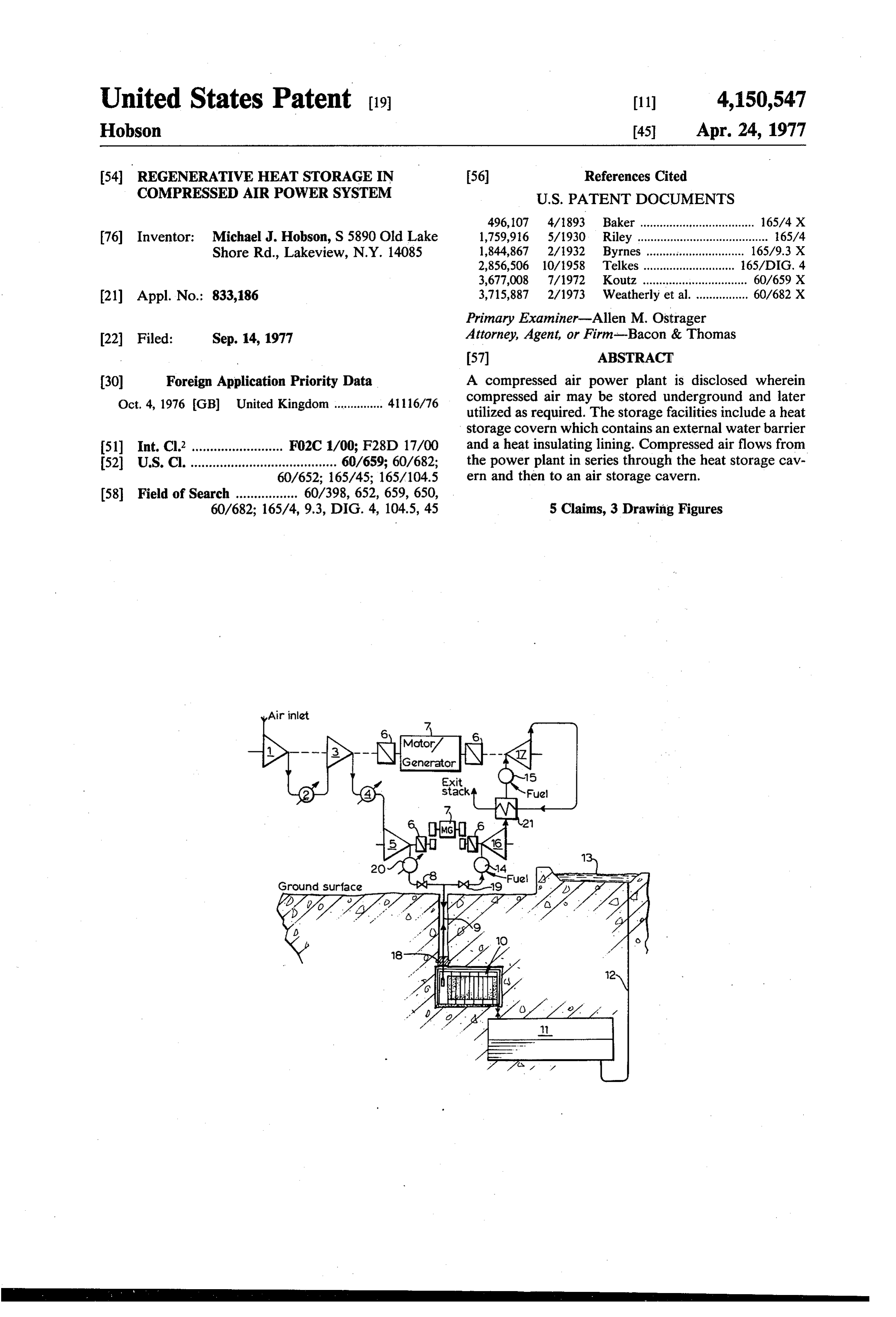
United States Patent (19) 11 4,150,547 Hobson 45 Apr. 24, 1977 54 REGENERATIVE HEAT STORAGE IN 56 References Cited COMPRESSED AIR POWER SYSTEM U.S. PATENT DOCUMENTS 496,107 4/1893 Baker ................................... 165/4 X 76) Inventor: Michael J. Hobson, S 5890 Old Lake 1,759,916 5/1930 Riley ........................................ 165/4 Shore Rd., Lakeview, N.Y. 14085 1,844,867 2/1932 Byrnes .............................. 165/9.3 X 2,856,506 10/1958 Telkes ........ ... 165/DIG. 4 3,677,008 7/1972. Koutz ................................ 60/659 X (21) Appl. No.: 833,186 3,715,887 2/1973 Weatherly et al. ................ 60/682 X Primary Examiner-Allen M. Ostrager 22 Filed: Sep. 14, 1977 Attorney, Agent, or Firm-Bacon & Thomas
(30) Foreign Application Priority Data A compressed air power plant is disclosed wherein Oct. 4, 1976 GB United Kingdom ............... 4116/76 compressed air may be stored underground and later utilized as required. The storage facilities include a heat storage covern which contains an external water barrier 51) Int. Cl? ......................... FO2C 1/00; F28D 17/00 and a heat insulating lining. Compressed air flows from 52 U.S. C. ........................................ 60/659; 60/682; the power plant in series through the heat storage cav 60/652; 165/45; 165/104.5 ern and then to an air storage cavern.
60/682; 165/4, 9.3, DIG. 4, 104.5, 45 5 Claims, 3 Drawing Figures
Air inlat
Ground surface
Page 2
Drawing sheet — no readable text.
Page 3
Drawing sheet — no readable text.
Page 4
tween the compressor and the heat storage cavern,
REGENERATIVE HEAT STORAGE IN whereby intermittently to cool the air being passed to COMPRESSED AIR POWER SYSTEM the latter so as to correct the gradual rise in mean tem perature occurring in the heat storage and air storage
CVS
FIELD OF THE INVENTION
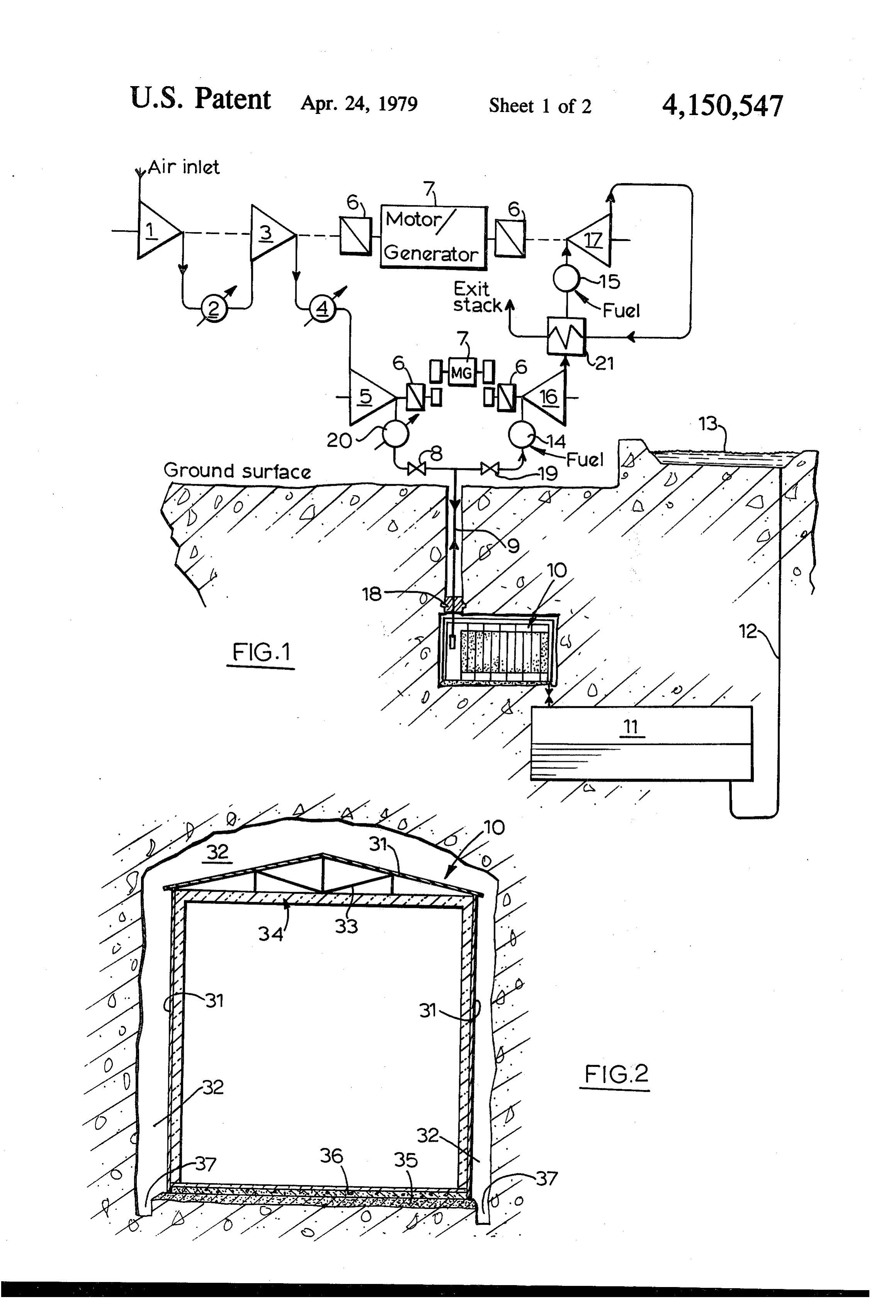
This invention relates to compressed air power stor SHORT DESCRIPTION OF THE DRAWINGS age systems in which power is stored by compressing A preferred embodiment of the invention is illus air and passing the latter to a storage cavern, whence it trated in the accompanying drawings, in which: is released as required. O FIG. 1 is a diagrammatic representation of a system in REVIEW OF THE PRIOR ART accordance with the invention, and
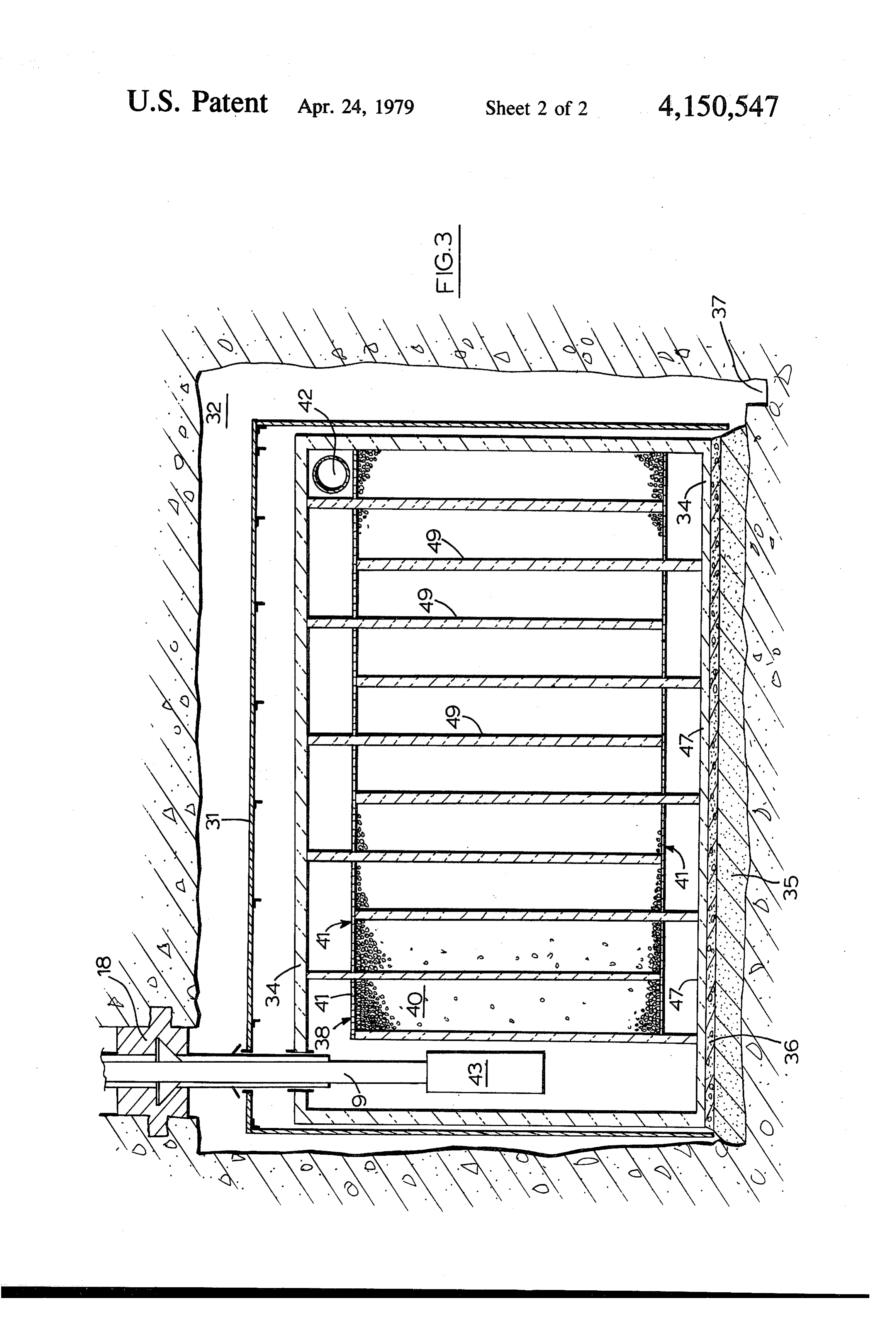
FIGS. 2 and 3 are vertical sections on perpendicular
Conventional compressed air power storage systems axes through the heat storage caverns incorporated in require cooling of the compressed air to 50 C. or below the system.
prior to injection into the storage cavern to prevent 15 excessive thermal cycling stresses in the cavern wall. DESCRIPTION OF THE PREFERRED The heat generated during compression is usually re EMBODIMENT jected to the environment via cooling towers or ponds. Referring to FIG. 1, and assuming that the com If some of this heat of compression could be stored for pressed air power storage system shown is operating in utilisation during the regeneration of the energy stored 20 its compression phase, air enters a low pressure com in the compressed air, a considerable improvement in pressor 1 and is discharged through an intercooler 2 to efficiency could be achieved. an intermediate compressor 3. An intercooler 4 cools A proposal to this effect is to be found in U.S. Pat. the air from the intermediate pressure compressor 3 No. 3,677,008 (S. L. Koutz) issued July 18, 1972. This prior to its entering a high pressure compressor 5. Com patent proposes the provision of a heat storage cavern 25 pressed air is discharged from the high pressure com between compression means on the ground surface and pressor at temperatures ranging from 200 to 300° C., a hydrostatically compensated underground air storage and thence via a control valve 8 and a normally inopera cavern. The heat storage medium is crushed rock which tive aftercooler 20 to an air supply pipe 9 descending fills the heat storage cavern. The possibility of provid through a vertical shaft from the ground surface to a ing heat insulation between the crushed rock and the heat storage cavern 10. The pipe 9 is heat insulated and cavern wall is mentioned, as is the requirement for heat supported in the air shaft in such a manner as to allow insulation in the air shaft connecting the cavern to the vertical expansion, whilst to seal the heat storage cav surface. ern against air leakage, a plug 18 is incorporated in the However, the arrangement proposed in U.S. Pat. No. shaft. The hot compressed air passes through the heat 3,677,008 still suffers from certain disadvantages. The 35 storage cavern 10 and is cooled by heat storage medium airflow through the heat storage cavern will tend to be contained therein; the design of the cavern is described uneven, and this lack of organization of the airflow will further below with reference to FIGS. 2 and 3. The cause the temperature of the bed to rise rapidly in re cooled air leaving the heat storage cavern is discharged gions adjacent the main airflow to a point where high to an air storage cavern 11, which is maintained at sub temperature air may be admitted to the storage cavern, stantially constant pressure as the entering air displaces again leading to excessive temperature cycling stresses water through a shaft 12 into a surface reservoir 13. in the cavern wall. Moreover, there will be a gradual During the regeneration phase, air is withdrawn from general rise of the mean temperature of the heat store, the cavern 11, through the heat storage cavern 10 and to some extent in the air storage cavern, over a where it is reheated by the hot heat storage medium. number of cycles, since thermodynamically the opera 45 The heated air rises up the air supply pipe 9, and passes tion of the system will not be entirely reversible. In each through a valve 19 to a heater 14, where heat may be cycle, the average temperature of the air entering the applied if required to adjust the temperature of the air to heat store on its way into the air storage cavern will be a desired level. The hot air is then admitted to a high higher than the average temperature of the same mass pressure turbine 16, where after the air is further heated of air leaving it during energy regeneration. Hence the SO in a heater 15 and admitted to a low pressure turbine 17 ability of the heat store to function effectively will grad whence it discharges to a stack via an optional recuper ually degrade. ator 21 which may be utilised to assist in heating the SUMMARY OF THE INVENTION gases passing between the turbines 16 and 17. The compressors 1, 3 and 5 and the turbines 16 and 17
According to the present invention, a compressed air 55 are coupled by clutches 6 to motor/generators 7, the power storage system comprises means for generating clutches 6 and the valves 8 and 19 being operated ac and utilizing compressed air, a compressed air storage cording to whether the system is being used to store cavern, a heat storage cavern containing a heat storage energy supplied in the form of electrical energy to the medium, a first air passage extending between the com motor/generators 7, or to regenerate stored energy in pressed air generating and utilizing means and the heat 60 the form of electrical energy output by the motor/gen storage cavern, and a second air passage extending erators. .
between the heat storage cavern and the air storage FIG. 2 is a cross section of the heat storage cavern 10 cavern, the internal structure of the heat storage cavern showing a housing for the heat storage medium (the being such as to define a serpentine path through the structure internal of the housing is omitted for the sake heat storage medium for air on passing through it be of clarity). A complete external water barrier 31, con tween the passages such as to ensure substantially uni structed of siding and roof sheeting, sheds all water form contact between the air and the medium. Prefera entering the cavity into channels 37 in the rock floor of bly a selectively operable aftercooler is connected be the cavern. These channels lead to the main air storage
Page 5
cavern which is located adjacent the heat storage cav heated air then passes through the filter 43 to remove ern and at a lower elevation. The roof sheeting is sup any carry over of particulate material, and passes up the ported by a light framework 33. A foundation for the supply pipe 9 to the surface plant. housing comprises a granular rock layer 35 and a con As mentioned above, the aftercooler 20 is normally crete floor 36. All of inner lining 34 of the housing inoperative, but from time to time it is utilised during formed by the barrier 31 and the floor 36 is heat insu the energy storage phase to cool the compressed air lated to make the lining heat insulating to retain heat before it is passed to the heat storage cavern 10, so as to and improve efficiency. Within the insulation are struc enable the mean temperature of the latter to be reduced, tural members (not shown) for support of the walls and and thus to compensate for the gradual rise in tempera roofs. An access space 32 is provided on all sides of and 10 ture of the cavern which will occur over a number of above the housing for inspection and maintenance pur operating cycles due to the imperfect efficiency of the poses, and so as to prevent any possible overheating of cycle.
the rock surface of the cavern. What I claim is:
Further details of the construction can be seen in 1. A compressed air power storage system compris FIG. 3. During the compression phase, the hot air en 15 ing means for generating and utilizing compressed air, a ters through the air pipe 9, which is sealed to the rock compressed air storage cavern, a heat storage cavern shaft through which it passes by the seal 18. The air containing a heat storage medium, a first air passage from the pipe 9 enters the housing through a filter 43. extending between the compressed air generating and The insulation 34 of the housing is not airtight and utilizing means and the heat storage cavern, a second air allows the pressures to equalise in the cavern through 20 passage extending between the heat storage cavern and the sheeting 31. Air flows from the filter 43 into a first the air storage cavern, and a housing for the heat stor pass 38 of heat storage medium 40 through a distribu age medium within the heat storage cavern, said hous tion plate 41. The storage medium in each pass is con ing being spaced from the walls and roof of the cavern fined top and bottom between two such plates 41, which are of perforated metal designed to establish 25 and lining having an external water barrier, a heat insulating within the barrier, and internal structure defining even flow distribution through the material. The mate a serpentine path through the heat storage medium for rial 40, which may be crushed rock, iron scrap or shot, passing air between the passages so as to ensure substan or other heat absorbent material, is sized to inhibit phys tially uniform contact between the air and the medium. ical breakdown due to temperature cycling and is 2. A compressed air power storage system according graded to larger sizes adjacent the top and bottom dis 30 to claim 1, wherein a selectively operable aftercooler is tribution plates. The weight of the bed in each pass is connected between the compressed air generating supported by the lower distribution plate, which in turn means and the first passage.
is supported by longitudinal beams 47, which maintain 3. A compressed air power storage system according even flow distribution in the lateral direction. The sev eral passes of storage medium are defined by interdigi 35 toin claim 1, wherein the space within the lining is divided a plurality of passes by interdigitating walls so as to tating heat insulating walls 49 extending alternately define said serpentine path, the heating storage medium from the top and bottom insulating walls of the enclo being retained between the interdigitating portions of sure to the bottom and top distribution plates 41 respec said walls.
tively so as to define a serpentine path for air through 4. A compressed air power storage system according the cavern. The number and size of the compartments are selected so as to obtain a reduction in air tempera to claim 3, wherein the heat storage cavern comprises ture to approximately 50° C. before the air leaves the heat drainage channels to capture water condensing in the cavern through an exit duct 42 to the air storage cavern barrier. store medium and shed from the external water
The moisture which condenses from the air during 45 5. A compressed air power storage system according cooling is conducted by drain channels beneath the to claim 1, wherein the means for generating and utiliz lower plates 41 to the main drain channels 37 in the ing the compressed air comprise low and high pressure cavern floor. compressors connected in series, and high and low pres When regeneration commences, the air from the main sure turbines, the low pressure compressor and turbine cavern enters the heat storage cavern by the duct 42 and 50 being connected to a first motor/generator and the high retraces in the opposite direction its previous path pressure compressor and turbine being connected to a through the passes of heat storage medium, in the mean second motor/generator. k is sk while absorbing heat from the hot storage medium. The
Provenance
- Collection
- Cited prior art
- Original PDF
- patentimages.storage.googleapis.com →
- Filed
- 1977-09-14
- Pages
- 5
- Method
- pdftotext (the PDF's own text layer) + pdftoppm 300dpi page scans
- Source
- Google Patents bibliographic record
- Granted
- 1979-04-24
- Inventors
- Michael J. Hobson
- Transcribed from
- patentimages.storage.googleapis.com →