patent · US4241781
Regenerative heater and process for the operation thereof
30 December 1980
Page 1 — bibliographic record
United States Patent (19) (11) 4,241,781 Eschner et al. 45 Dec. 30, 1980 (54) REGENERATIVE HEATER AND PROCESS Attorney, Agent, or Firm-Wenderoth, Lind & Ponack
FOR THE OPERATION THEREOF
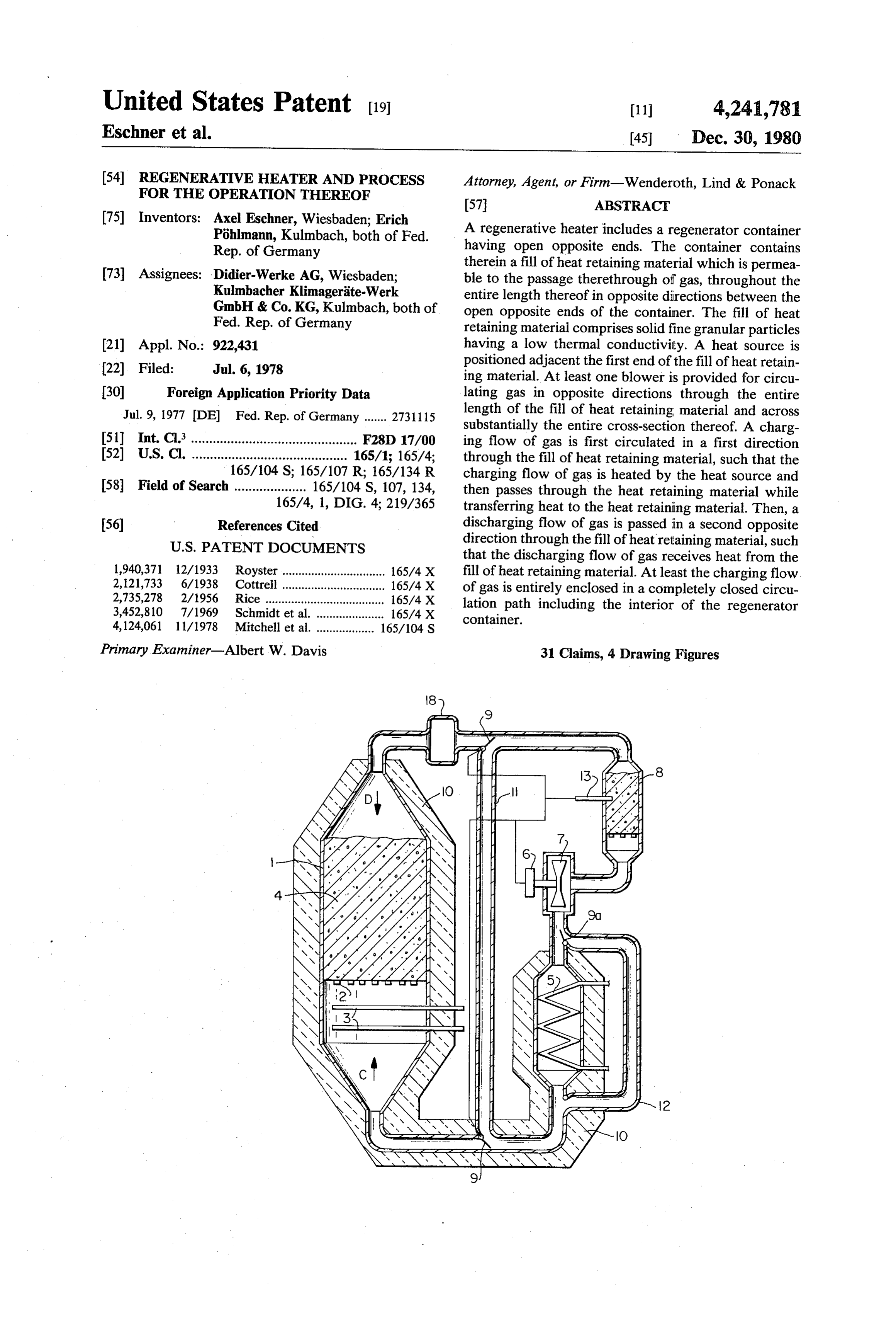
(75) Inventors: Axel Eschner, Wiesbaden; Erich A regenerative heater includes a regenerator container PÖhlmann, Kulmbach, both of Fed. having open opposite ends. The container contains Rep. of Germany therein a fill of heat retaining material which is permea 73) Assignees: Didier-Werke AG, Wiesbaden; ble to the passage therethrough of gas, throughout the Kulmbacher Klimageräte-Werk entire length thereof in opposite directions between the GmbH & Co. KG, Kulmbach, both of open opposite ends of the container. The fill of heat Fed. Rep. of Germany retaining material comprises solid fine granular particles (21) Appl. No.: 922,431 having a low thermal conductivity. A heat source is 22). Filed: Jul. 6, 1978 positioned adjacent the first end of the fill of heat retain ing material. At least one blower is provided for circu 30 Foreign Application Priority Data lating gas in opposite directions through the entire Jul. 9, 1977 (DE Fed. Rep. of Germany ....... 2731115 length of the fill of heat retaining material and across substantially the entire cross-section thereof. A charg 51 Int. Cl. .............................................. F28D 17/00 ing flow of gas is first circulated in a first direction 52 U.S. Cl. ........................................... 165/1; 165/4; through the fill of heat retaining material, such that the 165/104 S; 165/107 R; 165/134 R charging flow of gas is heated by the heat source and 58) Field of Search .................... 165/104 S, 107, 134, then passes through the heat retaining material while 165/4, 1, DIG. 4; 219/365 transferring heat to the heat retaining material. Then, a 56) References Cited discharging flow of gas is passed in a second opposite
that the discharging flow of gas receives heat from the 1,940,371 12/1933 Royster ................................ 165/4 X fill of heat retaining material. At least the charging flow 2,121,733 6/1938 Cottre . . 165/4 X of gas is entirely enclosed in a completely closed circu 2,735,278 2/1956 Rice ......... 165/4X lation path including the interior of the regenerator 3,452,810 7/1969 Schmidt et al. . ... 165/4 X container.
4,124,061 1 1/1978 Mitchell et al. .................. 165/104 S
Primary Examiner-Albert W. Davis 31 Claims, 4 Drawing Figures
Page 2
Drawing sheet — no readable text.
Page 3
Drawing sheet — no readable text.
Page 4
source is positioned adjacent a first end of the fill of heat
REGENERATIVE HEATER AND PROCESS FOR retaining material. A charging flow of gas is circulated THE OPERATION THEREOF in a first direction through the fill of heat retaining
BACKGROUND OF THE INVENTION
material such that the charging flow of gas is heated by 5 the heat source and then passes through the entire
The present invention relates to a regenerative heater length of the fill of heat retaining material, from the first and the process for the operation thereof, wherein the end thereof to a second opposite end thereof, and across regenerative heater includes a regenerator container substantially the entire cross-section thereof, while containing therein a fill of heat retaining material which transferring heat to the fill of heat retaining material. A is permeable to air and gas, wherein gas is conveyed 10 discharging flow of gas may then be circulated in a through the heat retaining material in opposite direc second direction opposite to the first direction through tions as charging and discharging flows of gas, and the fill of heat retaining material, such that the discharg wherein a source of heat is arranged in front of the heat ing flow of gas passes through the entire length of the retaining material taken in the direction of the charging 15 fill of heat retaining material, from the second end flow of gas. thereof to the first end thereof, and across substantially A regenerative heater of this type is known from the entire cross-section thereof, while receiving heat German DT-OS No. 1939 534. Such known regenera from the previously heated fill of heat retaining mate tive heater includes a regenerative oven containing a fill rial. At least the charging flow of gas is entirely en of ceramic particles provided in a bottle-like container closed in a completely closed circulation path which having a closed bottom and an open top. When the 20 includes the interior of the regenerator container. The regenerative oven is charged, air is led past a source of fill heat, through the open top of the container, and into the lar of heat retaining material comprises solid fine granu particles having a low thermal conductivity.
fill. After the air yields its heat to the fill, the air escapes During the charging operation, due to the fact that laterally to the exterior through the walls of the con the charging flow of gas passes through substantially tainer. During the discharging operation, fresh air is led 25 the entire cross-section of the fill, and also throughout laterally through the walls of the container and into the fill. After the air is heated by receiving heat from the the entire length of the fill, the fill is gradually warmed up in uniform layers extending across the entire cross fill, the air is removed through the upper open end of section thereof. That is, the charging flow of gas, heated the container. The operation of this known regenerative by the heat source, passes through the entire cross-sec heater is however disadvantageously affected by the tion of the first
end of the fill and therefore uniformly fact that both the charging and discharging flows of air are provided from relatively open circuits, and thus the heats up the entire cross-section of the fill adjacent the effects of heating the fill and heating the discharging first end thereof. As the fill particles adjacent the first flow of air are difficult to accurately control. The end absorb their maximum capacity of heat, later charg known regenerative heater is further disadvantageous 35 ing gas gradually uniformly warms up further layers of in that the charging air is removed from the container the fill particles across the entire cross-section of the fill. and the discharging air is introduced into the container Due to the fact that the fill particles have a low thermal through relatively small lateral openings in the walls of conductivity, the heating of the fill particles is achieved the container. This makes it very difficult to obtain entirely by heat transfer from the charging gas, and not contact between the respective flows of air and all of 40 by thermal conduction between the particles within the the ceramic particles in the fill. Thus, the heat exchange fill. Thus, the area of the fill adjacent the heat source is between the flows of gas and the particles of the fill is warmed up very rapidly to high temperatures, for ex inefficient. ample a temperature of approximately 800° C., while SUMMARY OF THE INVENTION the following areas of the fill are sequentially and grad 45 ually warmed up. The temperature gradient within the
With the above discussion in mind, it is a principle fill is relatively steep and travels gradually from the first object of the present invention to provide a regenera end of the fill to the second end of the fill during the tive heater and a process for the operation thereof duration of the charging operation. More particularly, whereby it is possible to obtain a very rapid and a very as a given volume or layer of the fill extending across highly efficient heat exchange between the fill of heat 50 the entire cross-section thereof is heated to a maximum retaining material and the charging and discharging temperature of absorption of a maximum capacity of flows of gas. heat, such given volume or layer cannot absorb further It is a further object of the present invention to pro heat from the charging flow of gas. Thus, successive vide such a regenerative heater and process for the portions of the charging flow of gas heat the next suc operation thereof whereby it is possible to obtain such 55 cessive layer or volume of fill spaced further from the improved heat exchange performance, even when the heat source.
charging operation is carried out for only very short The charging operation is maintained for a desired periods of time. length of time during which a desired portion or all of The above objects are achieved in accordance with the fill of heat retaining material is heated. Thereafter, the present invention by providing that the regenerative 60 the discharging flow of gas is circulated through the fill heater includes a regenerator container having open of heat retaining material in an opposite direction opposite ends and air or gas impermeable walls. A fill of thereof, but also throughout the entire length of the heat heat retaining material is positioned within the regener retaining material, and also across substantially the en ator container such that the fill of heat retaining mate tire cross-section thereof. Therefore, the discharging rial is permeable to the passage therethrough of air, 65 flow of gas is relatively rapidly heated to the desired throughout the entire length of the fill of heat retaining high temperature, since the discharging flow of gas material taken in opposite directions between the open cannot pass through any cross-sectional portion of the opposite ends of the regenerator container. A heat fill that has not been heated during the previous charg
Page 5
ing operation. Therefore, even if the charging operation or auxiliary regenerator container containing therein a is carried out for only a relatively short length of time, fill of heat retaining material similar to the fill of heat such that only the volume or layer of the fill adjacent retaining material in the main regenerator container. the heat source has been heated, the discharging flow of Thus, if the fill of heat retaining material in the main gas thereafter passing through the fill is still rapidly 5 regenerator container has absorbed its maximum capac heated to a desired temperature. Furthermore, due to ity of heat, then the heat thereafter retained in the the fact that the particles of the fill of heat retaining charging flow of gas will be absorbed in the fill of heat material have a low thermal conductivity, there will be retaining material within the auxiliary regenerator con no heat dissipation from a given cross-section of the fill tainer. The heat absorbed in the auxiliary regenerator due to thermal conduction among the particles of the 10 container will not be wasted, since upon the discharging fill. Therefore, a given cross-sectional area of the fill operation the discharging flow of gas will first flow which has been heated during charging operation will through the auxiliary regenerator container and receive maintain such heat until a later discharging operation. the previously absorbed heat therefrom. Additionally in accordance with the present inven In accordance with a further arrangement of the tion, at least the charging flow of gas is always main 15 present invention, there may be provided a conven tained and entirely enclosed within a completely closed tional temperature detector and thermostat which de circulation path which includes the interior of the re termines when the auxiliary regenerative heater has generator container. That is, the charging flow of gas is absorbed a predetermined maximum quantity of heat never made a portion of an open circuit. Accordingly, it from the charging flow of gas and for thereupon stop is much easier to maintain and control the efficiency of 20 ping operation of the blower. the charging operation. Further alternatively, the auxiliary regenerative Further, the discharging flow of gas may also be heater may be omitted, and a conventional temperature entirely enclosed in the completely closed circulation detector and thermostat may be provided adjacent the path. Alternatively, the discharging flow of gas may second end of the main generator container to thereby originate from the exterior of the completely closed 25 detect when the portion of the fill of heat retaining circulation path and may discharge gas which is heated material adjacent the second or downstream end of the by the fill of heat retaining material to a consumer exte fill, taken in the direction of the charging flow of gas, rior of the closed circulation path. has absorbed a maximum quantity of heat from the When both the charging and discharging flows of gas charging flow of gas, and for thereafter stopping opera are entirely enclosed within the completely closed cir 30 tion of the blower.
culation path, then the discharging flow of gas which is It is of course to be understood that when the dis heated by the fill of heat retaining material may transfer charging flow of gas originates exterior from the com heat to a heat exchanger, for example an indirect heat pletely closed circulation path, and only the blower for exchanger having one of the flow paths thereof within the charging flow of gas is included within the com the completely closed circulation path. 35 pletely closed path, the above described expedients may When both the charging and discharging flows of gas be employed for preventing overheating of the blower are maintained within the completely closed circulation for the charging flow of gas. The discharging flow of path, the circulation of both the charging and discharg gas may be employed for the direct heating of air, even ing flows of gas in opposite directions through the fill of when the discharging flow of gas is circulated only heat retaining material may be achieved by operation of 40 within the completely closed circulation path. How a reversibly operable single blower. When the discharg ever, as discussed above, in accordance with an advan ing flow of gas originates exterior of the completely tageous feature of the present invention, when the dis closed circulation path, then the circulation of the charging flow of gas is circulated only within the com charging flow of gas may be achieved by a first blower pletely closed circulation path, the discharging flow of which is provided within the completely closed circula- 45 gas transfers heat to a heat exchanger, for example an tion path, and the circulation of the discharging flow of indirect heat exchanger. Furthermore, when a heat gas may be achieved by a second blower positioned exchanger is provided as a portion of the completely exterior of the completely closed circulation path, the closed circulation path, then in accordance with an second blower being selectively connectable to the advantageous feature of the present invention, the com regenerator container. 50 pletely closed circulation path also includes a bypass for In accordance with a further feature of the present bypassing the charging flow of gas around the heat invention, there is provided means for preventing the exchanger, to thereby reduce resistance to circulation blower from becoming over-heated during the circula of the gas during the charging operation. Such bypass tion of the charging flow of gas. That is, during the flow of the charging flow of gas may be suitably regu charging operation, if the entire fill of heat retaining 55 lated by valves.
material absorbs its maximum capacity of heat, then if Furthermore, in all embodiments of the present in the charging operation is thereafter continued, the vention, during the circulation of the discharging flow charging flow of gas will maintain its heat after passage of gas it is possible to bypass a portion of such discharg through the fill of heat retaining material. If such heated ing flow of gas around the fill of heat retaining material. charging flow of gas were to be allowed to reach the 60 It is therefore easy to regulate the temperature of the blower which is maintained in the completely closed discharging flow of gas which is supplied to the con circulation path, the blower would be damaged. The sumer, e.g. the heat exchanger or the consumer exterior present invention includes means for preventing such of the completely closed circulation path. More particu damage to the blower. larly, instead of leading the entire discharging flow of Specifically, in accordance with one embodiment of 65 gas through the fill of heat retaining material, it is possi the present invention, it is possible to provide within the ble to bypass a portion of the discharging flow of gas closed circulation path, between the second end of the around the fill of heat retaining material and thereafter fill of heat retaining material and the blower, a second admix such portion with that portion of the discharging
Page 6
flow of gas which has passed through and been heated means of a support element. In one particularly advan by the fill of heat retaining material. The control of this tageous arrangement of the invention, the support ele bypassing operation may be automatically achieved, for ment is inclined toward the center of the regenerator example by means of a thermostat which measures the container so that the height of the fill in the center of the temperature of the discharging flow of gas exiting from regenerator container is greater than along the walls the fill of heat retaining material or passing to the con thereof. The support element may comprise a steel sumer, for example the heat exchanger or the consumer screen supported by a perforate plate, the screen having exterior of the completely closed circulation path. In a a mesh size to retain the fine granular solid particles of specific embodiment according to the present inven the fill. Alternatively however, the support element tion, wherein the system includes the above discussed 10 may comprise a filter plate formed of a temperature auxiliary regenerative heater, a thermostat may be em resistant concrete material, the support element thereby ployed to detect the temperature of the gas passing being easily manufactured as a single premanufactured through the auxiliary regenerative heater and to component having a desired geometrical configuration. thereby control valves regulating the passage of the The granular particles of the fill of heat retaining discharging flow of gas through the main fill of heat 15 material preferably have a particle size of from 0.5 to 3 retaining material and through the bypass. In any case, mm, and further preferably a particle size of from 1 to 3 and in all embodiments of the present invention, the mm. Such particle size provides that the fill of heat regulation of the portions of the discharging flow of gas retaining material will be permeable to gas, but also passing through the fill of heat retaining material and provides a reasonable resistance to the passage through bypassing the fill of heat retaining material may be regu 20 the fill of the gas so that the gas is exposed to a large lated by valves. surface area within the fill to thereby ensure a very Due to the fact that the gas flowing through the rapid heat transfer between the gas and the particles completely closed circulation path assumes substan during both the charging and the discharging opera tially different temperatures, and therefore also substan tions. Additionally, it is possible to provide that the fill tially different volumes, in accordance with a further 25 of heat retaining material includes a layer of granular feature of the present invention there is provided means particles, located directly above the support element, for preventing an over-pressure from occurring in a having a larger particle size of up to 10 mm, so that it is portion of the completely closed circulation path. Spe possible to employ a support element having a some cifically, the completely closed circulation path may what larger mesh size.
include one or more enlarged equalization chambers to 30 In accordance with an important feature of the pres absorb potential volume increases of the gas, and to ent invention, as mentioned above, the granular parti thereby prevent the occurrence of any over-pressure cles of the fill of heat retaining material must have a low which would otherwise result in the possible occur thermal conductivity. As employed herein the term rence of leaks in the system. Such leaks would not only "low thermal conductivity' is intended to mean that represent a loss of efficiency of the system, but would 35 there will be substantially no transfer of heat by thermal also present a potential danger to the surrounding envi conduction between the granular particles of the fill of ronment. heat retaining material, such that there will be no dissi It has been found that optimum efficiency of the pation or wandering of the heat absorbed in a given regenerative heater of the present invention is obtained volume of the fill during a charging operation to other when the length to width ratio of the fill of heat retain 40 volumes or areas of the fill. Preferably, the thermal ing material in the regenerator container is maintained conductivity of the granular particles of the fill of heat within certain limits. The term "length' as employed retaining material according to the present invention herein is intended to refer to the dimension of the fill should be lower than 2 kcal/mh'C. It is believed that from the first end thereof to the second end thereof, i.e. those skilled in the art will understand what types of the dimension of the fill between the open opposite ends 45 commercially available material will have the above of the regenerator container. Moreover, as employed discussed low thermal conductivity and which may be herein the term "width' refers to the dimension of the employed as the granular particles for the fill of the heat fill taken in a direction transverse to the above defined retaining material in accordance with the present inven length, that is the width of the fill is the transverse tion. However, examples of inexpensive material which dimension of the fill. It has specificially been found that 50 may be employed as the heat retaining material in ac optimum efficiency is obtained when the above defined cordance with the present invention are natural magne ratio is greater than one, preferably greater than 1.5, site and olivine. It is specifically to be understood how and lower than four, preferably lower than 2.5. ever that the present invention is not limited to the use It has further been found that the efficiency of the of these specific materials, but that other materials hav regenerative heater of the present invention is addition 55 ing the desired low thermal conductivity may be em ally maximized by providing baffles adjacent opposite ployed.
ends of the fill of heat retaining material, to thereby In accordance with a further feature of the present improve the uniform distribution of the respective flows invention, the material employed for the fill of heat of gas directed toward the respective ends of the fill. In retaining material has a specific moisture content such accordance with the present invention, the fill of heat 60 that upon transfer of such moisture to the flows of gas retaining material may be positioned vertically or hori during circulation thereof in the completely closed Zontally in a selected portion of the completely closed circulation loop, the gas will have a relative humidity circulation path. When the fill of heat retaining material which does not exceed 80%.
is provided horizontally, then the fill is supported by the In accordance with a further feature of the present gas impermeable walls of the regenerator container. 65 invention, the walls of the system, from the walls of the However, when the path of the flows of gas through the regenerator container to the position whereat the heat fill of heat retaining material extends vertically, then the from the discharging flow of gas is transferred to a fill is supported within the regenerator container by consumer, are enclosed with thermal insulation mate
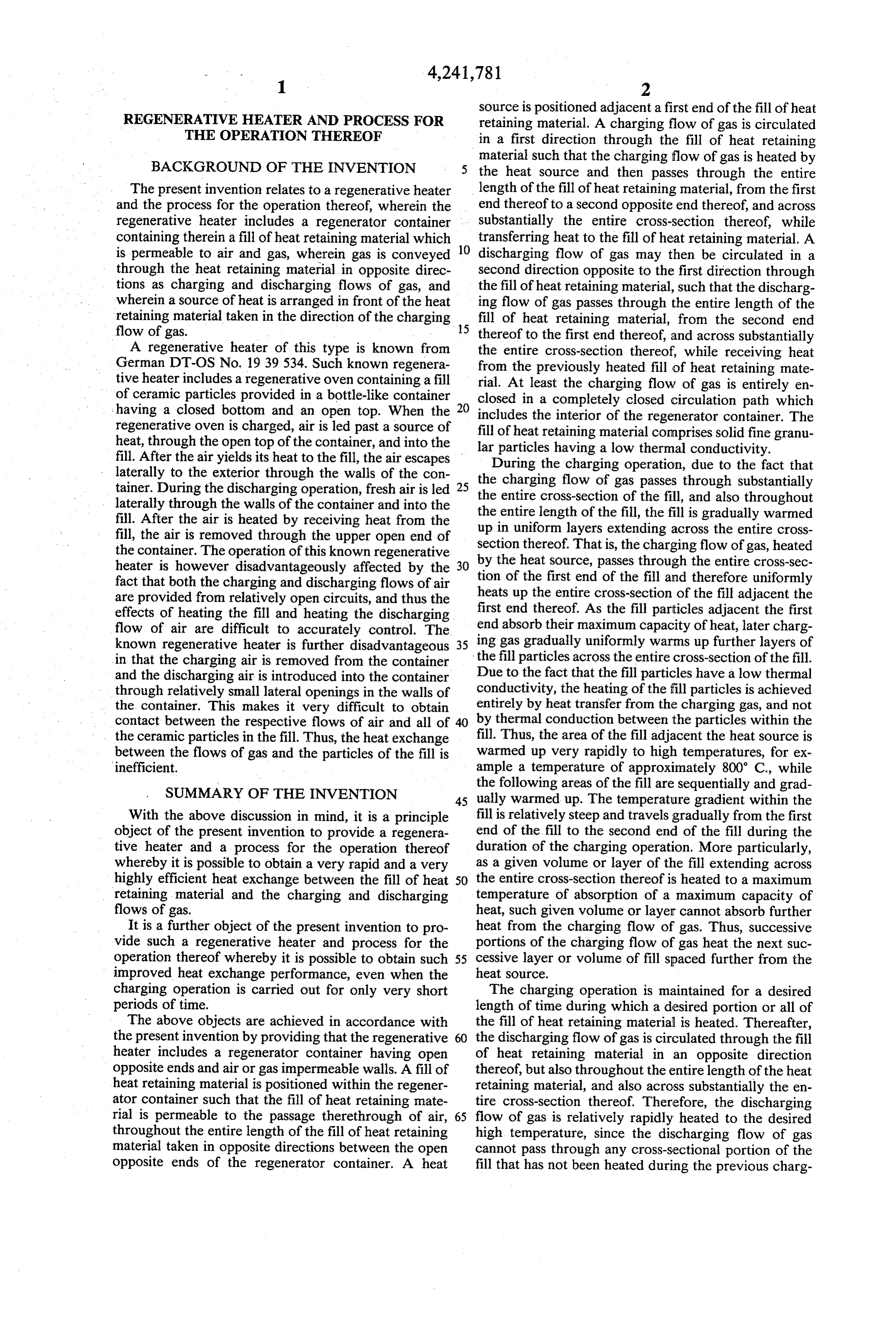
Page 7
rial, thereby further maintaining the efficiency of the support element 2a is inclined toward the center of the system. regenerator container 1 so that the height of the fill 4 in An additional advantage of the present invention is the center of the regenerator container is greater than that, when the demand on the system is so great that the along the walls thereof. The support element 2 may discharging flow of gas exiting from the fill of heat comprise a steel screen supported by a perforate plate, retaining material is not heated to the desired tempera the screen having a mesh size to retain the fine granular ture, such discharging flow of gas may be supplemen solid particles of the fill 4. Alternatively however, the tally heated by the heat source. This ensures that the support element may comprise a filter plate formed of a system is operable even during periods of very great temperature resistant concrete material. demand. O The granular particles of the fill of heat retaining In accordance with an even further advantageous material 4 preferably have a particle size of from 0.5 to feature of the present invention, it is possible to regulate 3 mm, and further preferably a particle size of from 1 to the operation of the regenerative heater as a function of 3 mm. This particle size provides that the fill of heat the amount of heat required by the consumer. For ex retaining material will be permeable to gas, but will also ample, it is possible to regulate the speed or RPM of the 15 provide a reasonable resistance to the passage through blower during the discharge operation as a function of the fill, so that the gas is exposed to a large surface area the heat required by the consumer, for example a heat within the fill to thereby assure a very rapid heat trans exchanger located in the completely closed circulation fer. However, it is additionally possible to provide that path or a consumer or load exterior to the completely the fill of heat retaining material 4 includes a layer of closed circulation path. granular particles, located directly above support ele BRIEF DESCRIPTION OF THE DRAWINGS ment 2, having a larger particle size of up to 10 mm. This makes it possible to employ a support element 2
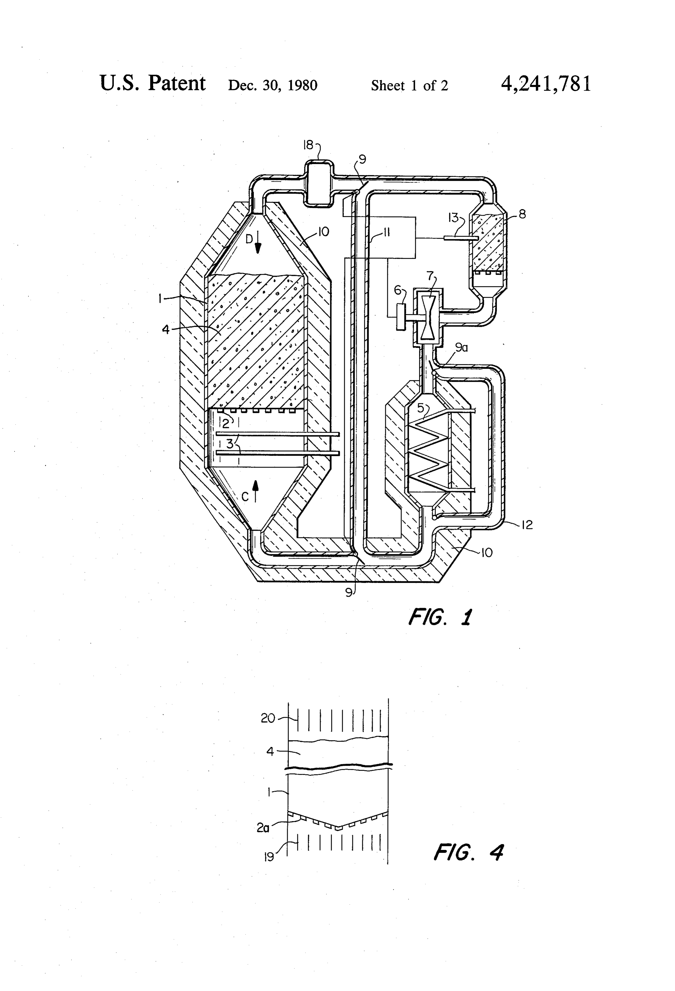
Other objects, features and advantages of the present having a somewhat larger mesh size.
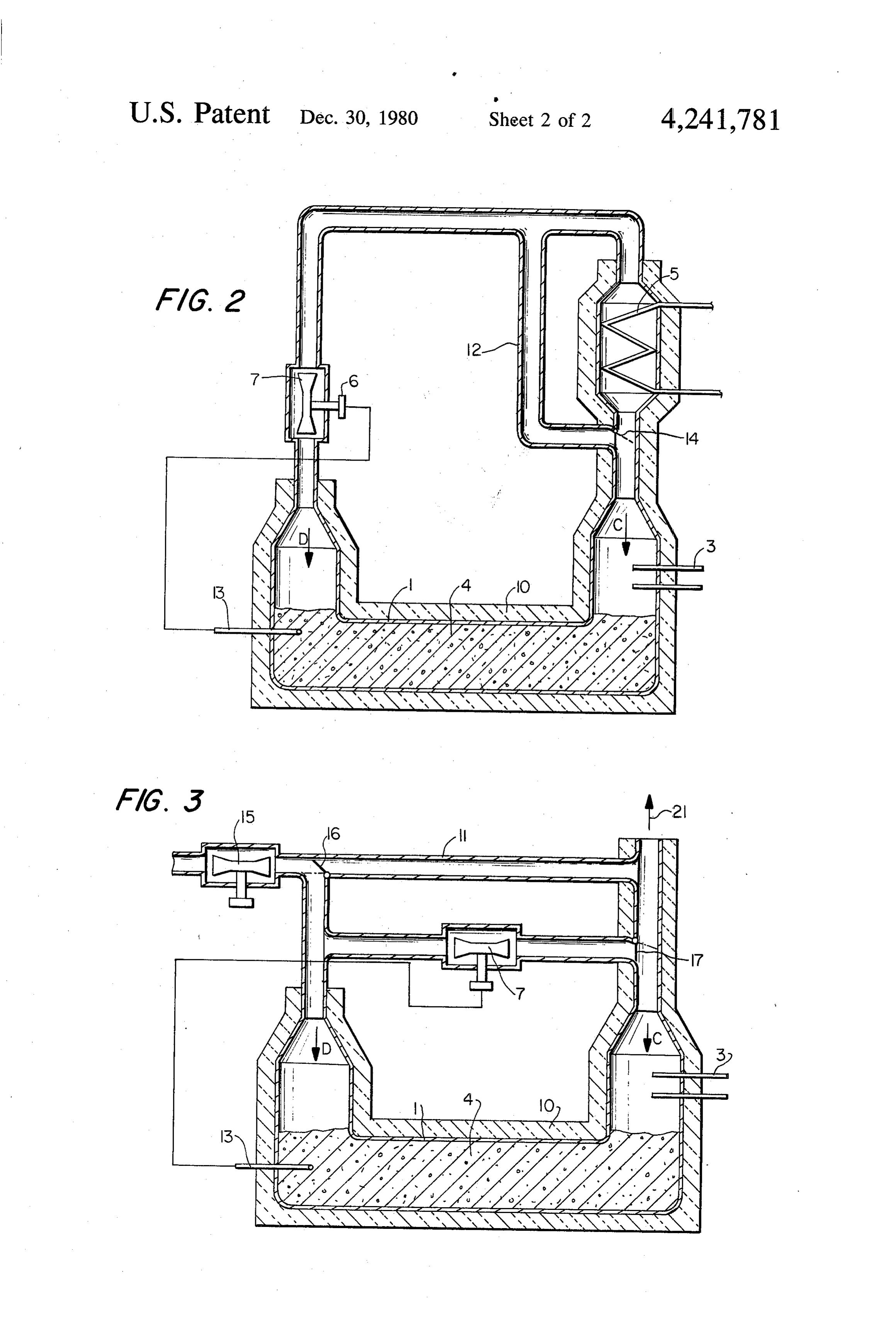
invention will become apparent from the following The granular particles of the fill of heat retaining detailed description thereof, taken with the accompany 25 material 4 must have a low thermal conductivity, so ing drawings, wherein: that there will be substantially no transfer of heat by FIG. 1 is a schematic cross-sectional view illustrating thermal conduction between the granular particles of a first embodiment of the present invention; the fill. Preferably, the thermal conductivity of the FIG. 2 is a schematic cross-sectional view illustrating granular particles of the fill of heat retaining material 4 a second embodiment of the present invention; 30 according to the present invention is lower than 2 FIG. 3 is a schematic cross-sectional view illustrating kcal/mh'C.
a third embodiment of the present invention; and In the embodiment illustrated, the heat source 3 is FIG. 4 is a schematic cross-sectional view illustrating schematically shown to comprise plural electrically a modification of a portion of the embodiment of FIG. controlled heating rods arranged one above the other at 1. 35 a position adjacent a first end of the fill of heat retaining material 4. It is however to be understood that heat
DETAILED DESCRIPTION OF THE
INVENTION source 3 may be in the form of any other conventional and known device for heating a flow of gas.
The regenerative heater of the embodiment of the In the operation of the regenerative heater shown in present invention illustrated in FIG. 1 includes a regen FIG. 1, the blower 7 is first operated in a first direction erator container having open opposite upper and lower to achieve a charging operation by circulating air ends and air-impermeable walls. The interior of regen around the completely closed circulation path in the erator container 1 forms a portion of a completely direction indicated by the arrow C. Thereby, the charg closed circulation loop or path which also includes a ing flow of gas is heated by heat source 3 and then second or auxiliary regenerator container 8, having a 45 passes through the entire length of the fill of heat retain smaller capacity than regenerator container 1, a blower ing material 4, from the first end thereof to the second 7 driven by a driving motor 6, a heat exchanger 5, and end thereof. An important feature of the present inven a heat source 3 positioned adjacent one open end of tion is that the charging flow of gas C passes through regenerator container 1. These various elements are the entire cross-section of the fill of heat retaining mate connected in a completely closed circulation path in 50 rial, thereby transferring heat to the entire cross-section any conventional manner, for example by means of the of the fill. Thus, the fill of heat retaining material 4 is piping which is schematically illustrated in FIG. 1. sequentially heated in layers or volumes extending Positioned within the interior of regenerator con across the entire cross-section thereof. Due to the fact tainer 1 is a fill of heat retaining material 4 comprising that the particles of the fill have a low thermal conduc solid fine granular particles having a low thermal con 55 tivity, heat is transferred to the fill only by the charging ductivity. The fill of heat retaining material 4 is permea flow of gas, and not by heat conduction between the ble to the passage therethrough of air or gas, through particles.
out the entire length thereof taken in opposite directions After the charging operation is maintained for a de between the open opposite ends of the regenerator con sired length of time during which a desired portion or tainer. In the embodiment shown in FIG. 1, the fill of 60 all of the fill of heat retaining material 4 is heated by the heat retaining material 4 is supported vertically within charging flow of gas C, the operation of blower 7 is the regenerator container 1, that is the charging and reversed so that there is circulated a discharging flow of discharging flows of gas C and D, respectively, pass gas D in a second opposite direction through the com vertically through the fill. Thus, the fill of heat retaining pletely closed circulation path. The discharging flow of material 4 is supported within the regenerator container 65 gas D also passes throughout the entire length of the fill 1 by means of a suitable support element 2. In one par of heat retaining material 4, throughout the entire cross ticularly advantageous arrangement of the invention, as section thereof, and the discharging flow of gas D schematically illustrated in FIG. 4 of the drawings, the thereby is unavoidably heated by the heat retained in
Page 8
the fill of heat retaining material. Due to the fact that discharging flow of gas D through the fill of heat retain during the charging operation an entire cross-sectional ing material 4, it is possible to bypass a portion of the volume portion of the fill is heated, then when the dis discharging flow of gas D around the fill of heat retain charging flow of gas D passes through the fill, the dis ing material 4 and thereafter admix such portion with charging flow of gas cannot avoid being rapidly heated. that portion of the discharging flow of gas which has The thus heated discharging flow of gas is then passed passed through and been heated by the fill. The regula to a suitable consumer, for example the heat exchanger tion of the portions of the discharging flow of gas pass 5 illustrated in FIG. 1. The discharging flow of gas D ing through the fill and passing through bypass 11 may thus gives up its heat to the fluid passing through the be regulated by valves, for example valves 9, as will be indirect heat exchanger in a conventional manner. 10 understood by those skilled in the art. This regulation Attention is directed to the fact that in accordance may be achieved automatically. Specifically, the above with a further feature of the present invention, the com described thermostat 13 may detect the temperature of pletely closed circulation path may include bypass pip the discharging flow of gas passing through auxiliary ing 12 for bypassing the charging flow of gas Caround regenerator container 8 after its passage through heat the heat exchanger 5 during the charging operation, 15 exchanger 5, and as a function of such temperature may thereby reducing resistance to circulation of the gas regulate the relative positions of valve 9 to control the during the charging operation. Such bypass flow of the relative opening and closing of bypass 11. charging flow of gas may be suitably regulated by Due to the fact that the gas flowing through the valves, for example valve 9a, as will be understood by completely closed circulation path assumes substan those skilled in the art. 20 tially different temperatures, and therefore also substan In accordance with a further feature of the present tially different volumes, in accordance with a further invention, baffles 19 and 20, as shown in FIG. 4, may be feature of the present invention there is provided means provided adjacent opposite ends of the fill of heat re for preventing an over-pressure from occurring in a taining material 4 to improve a uniform distribution of portion of the completely closed circulation path. Spe the respective flows of gas thereinto. 25 cifically, the completely closed circulation path may It will be understood that during the charging opera include one or more enlarged equalization chambers, tion, if the entire fill of heat retaining material 4 absorbs for example such as shown at 18 in FIG. 1, to absorb its maximum capacity of heat, then if the charging oper potential volume increases of the gas and to thereby ation is thereafter continued, the charging flow of gas C prevent the occurrence of any over-pressure which will maintain its heat after passage through the fill. If 30 would otherwise result in the possible occurrence of such heated charging flow of gas C were to be allowed leaks in the system.
to reach the blower 7, the blower would be damaged. Optimum efficiency of the regenerative heater of the Therefore, in accordance with a further feature of the present invention is obtained when the length to width present invention, there is provided means for prevent ratio of the fill of heat retaining material 4 in the regen ing such damage to the blower 7. Specifically, in accor 35 erator container 1 is maintained within certain limits. It dance with one embodiment of the present invention, it has specifically been found that optimum efficiency is is possible to provide within the closed circulation path, obtained when the above defined ratio is greater than between the fill of heat retaining material 4 and the one, preferably greater than 1.5, and lower than four, blower 7, a second or auxiliary regenerator container 8 preferably lower than 2.5.
containing therein an auxiliary fill of heat retaining In accordance with a further feature of the invention, material similar to the fill of heat retaining material 4. the walls of the completely closed circulation path, Thus, if the fill of heat retaining material 4 has absorbed including the walls of the regenerator container 1, the its maximum capacity of heat, then the heat thereafter walls of the heat exchanger 5, and the walls of the pip retained in the charging flow of gas C will be absorbed ing connecting the regenerator container and the heat in the fill of heat retaining material within the auxiliary 45 exchanger, are enclosed within a thermal insulation regenerator container 8. This heat absorbed in the auxil material 10, to thereby further increase the heat transfer iary regenerator container 8 will not be wasted, since efficiency of the system.
upon the discharging operation the discharging flow of In accordance with an even further feature of the gas D will first flow through the auxiliary regenerator present invention, the material employed for the fill of container and receive the previously absorbed heat 50 heat retaining material 4 has a specific moisture content therefrom. such that upon transfer of such moisture to the flows of In accordance with a further feature of the present gas during circulation thereof in the completely closed invention however, there may be provided a conven circulation path, the gas will have a relative humidity tional temperature detector and thermostat 13, schemat which does not exceed 80%.
ically shown in FIG. 1, which determines when the 55 As mentioned above, in the embodiment of the pres auxiliary regenerative heater has absorbed a predeter ent invention shown in FIG. 1, the fill of heat retaining mined maximum quantity of heat from the charging material 4 is positioned vertically within regenerator flow of gas C and which thereupon stops operation of container 1 and is supported therein by means of sup the motor 6 of blower 7. port element 2. However, it is also possible in accor Thereby, it is possible to prevent damage of the 60 dance with the present invention that the fill of heat blower 7 due to overheating thereof. retaining material 4 be supported horizontally within In accordance with a further feature of the present the regenerator container, and specifically on the air invention, it is possible to regulate the temperature of impermeable walls thereof. Such an arrangement is the discharging flow of gas which is passed to the con shown schematically in FIG. 2 of the drawings, and in sumer, such as the heat exchanger 5. Specifically, a 65 this arrangement the provision of support element 2 is portion of the discharging flow of gas D may be by not necessary. The embodiment of FIG. 2 may be in all passed around the fill of heat retaining material 4 by other respects identical to the embodiment of FIG. 1 as means of bypass 11. That is, instead of leading the entire described above. However, the arrangement of FIG. 2
Page 9
of the drawings does not disclose equalization chamber provide a regulation of the temperature of the discharg 18 or bypass 11. It is however to be understood that ing flow of gas which is supplied to the consumer. This such elements could be included in the arrangement of may be achieved in a manner similar to that described FIG. 2. above with regard to FIG. 1.
Additionally, the embodiment of FIG. 2 illustrates a With regard to all of the embodiments described revised arrangement for preventing overheating of the above, when the demand of the consumer on the system blower 7. Specifically, in the arrangement of FIG. 2 is so great that the discharging flow of gas D exiting there is no provision for the auxiliary regenerator con from the fill of heat retaining material 4 is not heated to tainer 8. Rather, temperature detector and thermostat the desired temperature, such discharging flow of gas D 13 are provided adjacent the second end of the regener 10 may be supplementally heated by operation of the heat ator container 1 to thereby detect when the portion of source 3. This ensures that the system is operable even the fill of heat retaining material 4 adjacent the second during periods of very great demand. or downstream end of the fill, taken in the direction of Additionally, in all embodiments of the present inven the charging flow of gas C, has absorbed a maximum tion, it is possible to regulate the operation of the regen quantity of heat from the charging flow of gas, and for 15 erative heater as a function of the amount of heat re thereafter stopping operation of the driving motor 6 of quired by the consumer. For example, it is possible to blower 7. regulate the speed or RPM of the blowers 7 or 15 dur Additionally, FIG. 2 illustrates that bypass 12 for ing the discharging operation as a function of the heat bypassing the charging flow of gas C around the heat required by the consumer.
exchanger 5 may be opened and closed by a valve 14 20 Although the present invention has been described arranged between the heat source 3 and the heat ex above with regard to specific structural arrangements changer 5. and operating features, it is to be understood that vari Except as noted hereinabove, the embodiment of ous modifications and alterations of such features may FIG. 2 is the same as and may be adapted to include the be made without departing from the scope of the pres above discussed features of the embodiment of FIG. 1. 25 ent invention.
In both of the above described embodiments of What we claim is:
FIGS. 1 and 2, both the charging and discharging flows 1. A regenerative heater comprising: of gas are entirely enclosed and circulated within the a regenerator container having open opposite ends completely closed circulation path. However, it is in and air-impermeable walls; tended to be within the scope of the present invention 30 a fill of heat retaining material positioned within said that, while the charging flow of gas C is always main regenator container, said fill of heat retaining mate tained within the completely closed circulation path, rial comprising solid fine granular particles having the discharging flow of gas D may originate from a a low thermal conductivity, and said fill of heat source exterior of the completely closed circulation retaining material being permeable to the passage path and may discharge gas which is heated by the fill 35 therethrough of air, throughout the entire length of heat retaining material to a consumer exterior of the thereof taken in opposite directions between said closed circulation path. Such an arrangement is shown open opposite ends of said regenerator container; in FIG. 3. a heat source positioned adjacent a first end of said fill More particularly, as shown in FIG. 3 of the draw of heat retaining material;
ings, a completely closed circulation path for the circu- 40 means for circulating a charging first flow of gas in a lation of charging flow of gas C includes the interior of first direction through said fill of heat retaining regenerator container 1 and blower 7. However, the material, such that said charging flow of gas is discharging flow of gas originates from an exterior heated by said heat source and then passes through source and is circulated by a second blower 15 which the entire length of said fill of heat retaining mate may be selectively coupled to and closed off from the 45 rial, from said first end thereof to a second opposite interior of regenerator container 1 by valve 16. Also, end thereof, and across substantially the entire blower 15 operates to supply the discharging flow of cross-section thereof, while transferring heat to gas, after being heated by the fill of heat retaining mate said fill of heat retaining material; rial 4, to an exterior consumer, as schematically illus means for circulating a discharging second flow of trated by arrow 21. Such consumer is selectively con 50 gas in a second direction opposite to said first direc nected to and closed off from the interior of the regen tion through said fill of heat retaining material, erator container 1 by valve 17. such that said discharging flow of gas passes In the operation of the embodiment of FIG. 3, when through the entire length of said fill of heat retain the device is operated during the charging operation, ing material, from said second end thereof to said then valves 16 and 17 are in the positions shown by the 55 first end thereof, and across substantially the entire dashed lines thereof in FIG. 3. Blower 7 is operated to cross-section thereof, while receiving heat from pass charging flow of gas C by heat source 3 and then said fill of heat retaining material; through the fill of heat retaining material 4. After the fill said charging and discharging flows of gas being of heat retaining material 4 is heated to a desired degree, entirely enclosed in a completely closed circulation blower 7 is stopped, and valves 16 and 17 are moved to 60 path including the interior of said regenerator con the positions thereof shown by the solid lines in FIG. 3. tainer; and
Then, second blower 15 is operated to circulate dis said means for circulating a charging flow of gas and charging flow of gas D through the fill of heat retaining said means for circulating a discharging flow of gas material 4 and then to consumer 21. It is additionally to comprising a single reversibly operable blower be understood that in accordance with the embodiment 65 positioned in said completely closed circulation of FIG. 3, bypass 11 may be provided to selectively loop.
bypass a portion of the discharging flow of gas D 2. A regenerative heater as claimed in claim 1, further around the fill of heat retaining material, to thereby comprising a heat exchanger positioned in said com
Page 10
pletely closed circulation path at a location between 17. A regenerative heater as claimed in claim 15, said blower and said heat source. wherein said support comprises a perforate plate and a 3. A regenerative heater as claimed in claim 2, metal screen supported by said perforate plate. wherein said completely closed circulation path com 18. A regenerative heater as claimed in claim 15, prises bypass means for bypassing said charging flow of 5 wherein said support comprises a porous filter plate gas around said heat exchanger. formed of a temperature resistant concrete material. 4. A regenerative heater as claimed in claim 1, further 19. A regenerative heater as claimed in claim 15, comprising means for preventing said blower from be wherein said fill of heat retaining material includes a coming overheated during the circulation of said charg layer of granular particles, located directly above said ing flow of gas. 10 support, having a particle size of up to 10 mm. 5. A regenerative heater as claimed in claim 4, 20. A regenerative heater as claimed in claim il, wherein said preventing means comprises an auxiliary wherein said granular particles of said fill of heat retain heat regenerator positioned in said completely closed ing material have a particle size of from 0.5 to 3 mm. circulation path at a location between said second end 15 21. A regenerative heater as claimed in claim 20, of said fill of heat retaining material and said blower, wherein said particle size is from 1 to 3 mm. such that extra heat from said charging flow of gas, 22. A regenerative heater as claimed in claim 1, after said fill of heat retaining material has absorbed its wherein the thermal conductivity of said fill of heat capacity of heat, is retained in said auxiliary heat regen retaining material is lower than 2 kcal/mh'C. erator and is prevented from reaching said blower. 20 23. A regenerative heater as claimed in claim 1, 6. A regenerative heater as claimed in claim 5, wherein said fill of heat retaining material has a specific wherein said preventing means further comprises ther moisture content such that upon transfer of said mois mostat means, operatively connected to said blower, for ture to said gas during circulation thereof in said com determining when said auxiliary heat regenerator has pletely closed circulation path, said gas will have a absorbed a predetermined maximum quantity of heat relative humidity not exceeding 80%. 24. A process for regeneratively heating gas, said from said charging flow of gas and for thereafter stop 25 process comprising:
ping operation of said blower. providing a regenerator container having opposite 7. A regenerative heater as claimed in claim 4, ends and air-impermeable walls; wherein said preventing means comprises thermostat positioning within said regenerator container a fill of means, operatively connected to said blower, for deter 30 heat retaining material comprising solid fine granu mining when said fill of heat retaining material has lar particles having a low thermal conductivity, absorbed a predetermined maximum quantity of heat such that said fill of heat retaining material is per from said charging flow of gas and for thereafter stop meable to the passage therethrough of air, through ping operation of said blower. out the entire length thereof taken in opposite di 8. A regenerative heater as claimed in claim 1, 35 rections between said open opposite ends of said wherein said completely closed circulation path com regenerator container;
prises bypass means for bypassing a portion of said positioning a heat source adjacent a first end of said discharging flow of gas around said fill of heat retaining fill of heat retaining material; material.
9. A regenerative heater as claimed in claim 1, 40 circulating tion a charging first flow of gas in a first direc through said fill of heat retaining material, wherein said completely closed circulation path further such that said charging flow of gas is heated by said comprises means for preventing an over-pressure heat source and then passes through the entire therein.
10. A regenerative heater as claimed in claim 9, length of said fill of heat retaining material, from wherein said preventing means comprises an enlarged 45 said first end thereof to a second opposite end equalization chamber. thereof, and across substantially the entire cross 11. A regenerative heater as claimed in claim 1, section thereof, while transferring heat to said fill of heat retaining material;
wherein the ratio of the length of said fill of heat retain circulating a discharging second flow of gas in a ing material, between said first and second ends thereof, second direction opposite to said first direction to the transverse width thereof is greater than 1 and SO through said fill of heat retaining material, such smaller than 4. that said discharging flow of gas passes through the 12. A regenerative heater as claimed in claim 11, entire length of said fill of heat retaining material, wherein said ratio is greater than 1.5. from said second end thereof to said first end 13. A regenerative heater as claimed in claim 11, thereof, and across substantially the entire cross wherein said ratio is smaller than 2.5. 55 section thereof, while receiving heat from said fill 14. A regenerative heater as claimed in claim 1, fur of heat retaining material;
ther comprising baffle means positioned adjacent said entirely enclosing said charging and discharging first and second ends of said fill of heat retaining mate flows of gas to flow in a completely closed circula rial for uniformly distributing the respective said flows tion path including the interior of said regenerator of gas throughout the cross-sections of said first and 60 container; and
Second ends. said steps of circulating said charging and discharg 15. A regenerative heater as claimed in claim 1, ing flows of gas comprising passing said charging wherein said fill of heat retaining material is supported and discharging flows of gas in opposite directions within said regenerator container by means of a support in said completely closed circulation path by re which is permeable to air. 65 versibly operating a single blower positioned 16. A regenerative heater as claimed in claim 15, within said completely closed circulation path. wherein said support inclines inwardly toward the cen 25. A process as claimed in claim 24, further compris ter of said regenerator container. ing circulating said discharging flow of gas through a
Page 11
heat exchanger located in said completely closed circu gas remaining therein after said fill of heat retaining material has absorbed its capacity of heat.
lation path. 29. A process as claimed in claim 28, wherein said 26. A process as claimed in claim 25, further compris preventing further comprises detecting when said auxil ing bypassing said charging flow of gas around said heat 5 iary heat regenerator has absorbed a predetermined exchanger. maximum quantity of heat from said charging flow of 27. A process as claimed in claim 24, further compris gas, and thereafter stopping operation of said blower. 30. A process as claimed in claim 27, wherein said ing preventing said blower from becoming overheated preventing comprises detecting when said fill of heat during said circulation of said charging flow of gas. O retaining material has absorbed a predetermined maxi 28. A process as claimed in claim 27, wherein said mum quantity of heat from said charging flow of gas, preventing comprises passing said charging flow of gas, and31.thereafter
A process stopping operation of said blower.
as claimed in claim 24, further compris after passage thereof through said fill of heat retaining ing bypassing a portion of said discharging flow of gas material, through an auxiliary heat regenerator and 15 around said fill of heat retaining material.
absorbing therein extra heat from said charging flow of
Provenance
- Collection
- Cited prior art
- Original PDF
- patentimages.storage.googleapis.com →
- Filed
- 1978-07-06
- Pages
- 11
- Method
- pdftotext (the PDF's own text layer) + pdftoppm 300dpi page scans
- Source
- Google Patents bibliographic record
- Granted
- 1980-12-30
- Inventors
- Axel Eschner; Erich Pohlmann; Didier Werke AG; KULMBACHER KLIMAGERATE WERK GmbH and Co KG
- Transcribed from
- patentimages.storage.googleapis.com →