patent · US4148701
High efficiency energy transfer technique
10 April 1979
Page 1 — bibliographic record
United States Patent (19) 11 4,148,701 Leach 45) Apr. 10, 1979 (54) HIGH EFFICIENCY ENERGY TRANSFER 57 ABSTRACT TECHNIQUE An apparatus is disclosed for exothermically obtaining 76 Inventor: Sam L. Leach, P.O. Box 2536, Palos hydrogen or hydrogen peroxide from water vapor in a Verdes Peninsula, Calif. 90274 reaction chamber. The separation of the hydrogen and oxygen may be accelerated through the use of a combi (21) Appl. No.: 834,682 nation host and sensitizer material which is present near 22 Filed: Sep. 19, 1977 spaces or voids within the reaction chamber. The water vapor has certain particular absorption bands in its ab
Related U.S. Application Data sorption versus frequency characteristic. Each of the (63. Continuation-in-part of Ser. No. 790,320, Apr. 25, sensitizers which are located adjacent the voids in the
reactant, in one embodiment forming part of the walls of small cylindrical tubes, has an energy output in the 51 Int. C.’................................................ B01J 1/10 excited state which is precisely in one of the energy 52 U.S. C. .................... 204/157.1 R; 204/DIG. 11; absorption bands in the water vapor characteristic. The 250/527 host material absorbs heat energy and excites the sensi 58) Field of Search .................... 204/157.1 R, 158 R; tizer material. In addition to the formation of free hy 250/527; 423/657, 658,584 drogen, some hydrogen peroxide is also formed. Other 56) References Cited feedstocks may have energy selectively applied to them.
1,345,905 7/1920 Abbott ................................. 423/657 ation to feedstock include (1) a reaction chamber in 3,443,087 5/1969 Robieux et al. ............. 204/DG, 11 which conductive wires are coated with two different 3,904,500 9/1975 Jenson ......................... 204/OIG, 11 host and sensitizer materials; and (2) a reaction chamber 3,969,204 7/1976 Neimann et al. ............ 204/DIG. 11 irradiated by beams from two lasers of different fre 4,045,359 8/1977 Fletcher ...................... 204/DIG. 11 quencies. In both of these apparatus the radiation of two OTHER PUBLICATIONS different frequencies beat together as the radiation im pinges on the media discontinuities provided by the
Steinberg, Advances in Science & Technology, vol. 1 feedstock and creates new sum and difference frequen (1962) pp. 309, 312 & 313. cies, with the higher sum frequencies providing ener Primary Examiner-Howard S. Williams getic radiation effects.
Attorney, Agent, or Firm-Poms, Smith, Lande, Glenny & Rose 32 Claims, 23 Drawing Figures
(INTERMITTENT)
OTHER FEED STOCK
(CONTINUOUS FLOW)
STEAM
Page 2
Drawing sheet — no readable text.
Page 3
Drawing sheet — no readable text.
Page 4
Drawing sheet — no readable text.
Page 5
Drawing sheet — no readable text.
Page 6
Drawing sheet — no readable text.
Page 7
Drawing sheet — no readable text.
Page 8
Drawing sheet — no readable text.
Page 9
Drawing sheet — no readable text.
Page 10
Drawing sheet — no readable text.
Page 11
Drawing sheet — no readable text.
Page 12
Drawing sheet — no readable text.
Page 13
Drawing sheet — no readable text.
Page 14
Drawing sheet — no readable text.
Page 15
/ / / M / M M / / / / / / M
Eess Z
PRODUCT S2-378
NNR RN, 71 CERAMIC
AIR-- N21
N REACTION
12 CHAMBER
EMITTER STANLESS FLAMENTS STEELTUBE
CERAMIC
388 N d
FOAM Sirritor - 382
REACTION
ressor ANN,
N \ \\\\ NYNNNNNNY YY N
Page 16
Drawing sheet — no readable text.
Page 17
Drawing sheet — no readable text.
Page 18
will be considered in detail in the body of the present
HGH EFFICIENCY ENERGY TRANSFER specification.
TECHNIQUE In addition to accelerating the generation of hydro gen by the application of high levels of energy to water
This patent application is a continuation-in-part of 5 vapor, instead of by sequestering the oxygen in the
1977, now U.S. Pat. No. 4,113,589. levles, the present apparatus also permits direct forma RELATED PATENT APPLICATIONS tion of hydrogen peroxide after the water vapor mole cule is broken up, as this is the preferred combinational
The subject matter of the present specification is 10 form of hydrogen and oxygen at the elevated tempera related to that disclosed in the specification of U.S. tures and pressures which are present in the reaction Patent application Ser. No. 768,868, filed Feb. 15, 1977, chamber.
and entitled, "Method and Apparatus for Generating In accordance with a broader aspect of the invention, Hydrogen'. an improved technique is provided for increasing the 15 efficiency of application of radiant energy to a feed
BACKGROUND OF THE DISCLOSURE stock. This is accomplished through the use of the heat This invention relates to apparatus and method for reservoir including a mass of material, a wire, or other increasing the efficiency and amplifying the effective element heated up to an elevated temperature, and the ness of energy transfer, particularly from a high temper 20 use of special sensitizer material and host material for ature source of energy. absorbing energy from the heat reservoir and for apply In the specification of the patent application cited ing energy to the feedstock at precisely those bands in above, an apparatus is described in which hydrogen the frequency spectrum at which the feedstock has high and/or hydrogen peroxide is formed exothermically absorption to radiant energy. In function, the host mate from water vapor, using a body of material such as 25 rial absorbs heat energy from the heat reservoir and manganese oxide raised to a high temperature to seques applies energy at a specific frequency sufficient to raise ter the oxygen from the water vapor. The process takes the sensitizer material to an excited state. The sensitizer place at relatively high pressure above about 5 atmo is chosen so that, as it shifts from its excited state to a spheres, and at a temperature in the order of 1000 cisely lower or ground energy state, it radiates energy pre Kelvin. After the hydrogen is drawn off at relatively 30 choosing in the absorption band of the feedstock. By high pressure, a check valve closes, and the oxygen is excitationalevel, suitable sensitizer, and exciting it to its upper removed from the manganese oxide at a reduced pres sensitizer in the aexcited population inversion of atoms of the state is produced, so that, as sure well below atmospheric pressure, by the use of a certain of these atoms drop to their lower energy states vacuum for example.
As the hydrogenis being drawn off from the reactions this will coherent radiation from large numbers of these chamber, the formation of hydrogen peroxide was dis sensitizer atoms with the result that very intense and concentrated radiation impinges on the feedstock pre closed, through the use of a venturi unit by which oxy cisely at the energy levels to which it is most sensitive. gen from the atmosphere was combined at high temper One particular advantage of the present invention is ature with the hydrogen. the increased speed and higher efficiency of energy SUMMARY OF THE INVENTION 40 transfer which is achieved by the use of the host and sensitizer materials. In the specific case of the water
In accordance with one limited and specific aspect of vapor, the invention, the breakup of the water vapor molecu the oxygen; for example, it is not necessary to sequester all of lar, H2O, may be accomplished more rapidly and effec are broken up, instead, many of the water vapor molecules and hydrogen peroxide is immediately tively through the use of sensitizer materials and host 45 formed. If desired, additional oxygen may be brought materials which absorb heatenergy from the manganese into the reaction chamber along with the water vapor to dioxide or other reactant and radiate energy which is provide more complete conversion of the water vapor concentrated in the high absorption portions of the to hydrogen peroxide.
absorption versus frequency characteristic of water vapor to break up the water vapor molecule. 50 tainIn embodiments accordance with an advantageous feature of cer of the invention, the application of
This action is enhanced through the use of small cells energy derived from the heated reactant to the feed which form voids throughout the reactant, and which stock may be accomplished with the feedstock in ther are provided with the special sensitizer and host mate mally conductive relationship, but isolated from the rial around the periphery of the voids. These voids may chamber in which the reactant is located, so that the be produced by wire mesh cells, or by ceramic cylin- 55 feestock may be irradiated continuously, while the reac ders having wire mesh at each end, for example, so that the water vapor may readily pass through the cylinders. tantis (exothermically) sequestering oxygen from water vapor at a high pressure, and subsequently dissociating
The wire mesh or the walls of the cylinders contain the the oxygen at a low pressure. The walls of the pipes or special host and sensitizer materials which apply highly other structure for separating the feedstock from the concentrated radiation to the water vapor at precisely 60 reactant may include the host/senstizer material, or the frequency bands at which the water vapor absorbs may be transparent to the radiations being directed from energy. It is also believed that the atomic radiations the adjacent host/sensitizer material to the feedstock. from the sensitizer material are coherent and thus apply In accordance with an additional feature of the inven an unusally high level of concentrated radiation to the tion high efficiency energy transfer to a feedstock may water vapor. The nature of the phenomena which are 65 be accomplished by the use of a reaction chamber, in involved and several specific examples of host and sen cluding wires coated with host and sensitizer material of sitizer materials both for water vapor and for other the type discussed above, for transforming broadband feedstocks to which it is desired that energy be applied, heat energy into radiation in the specific absorption
Page 19
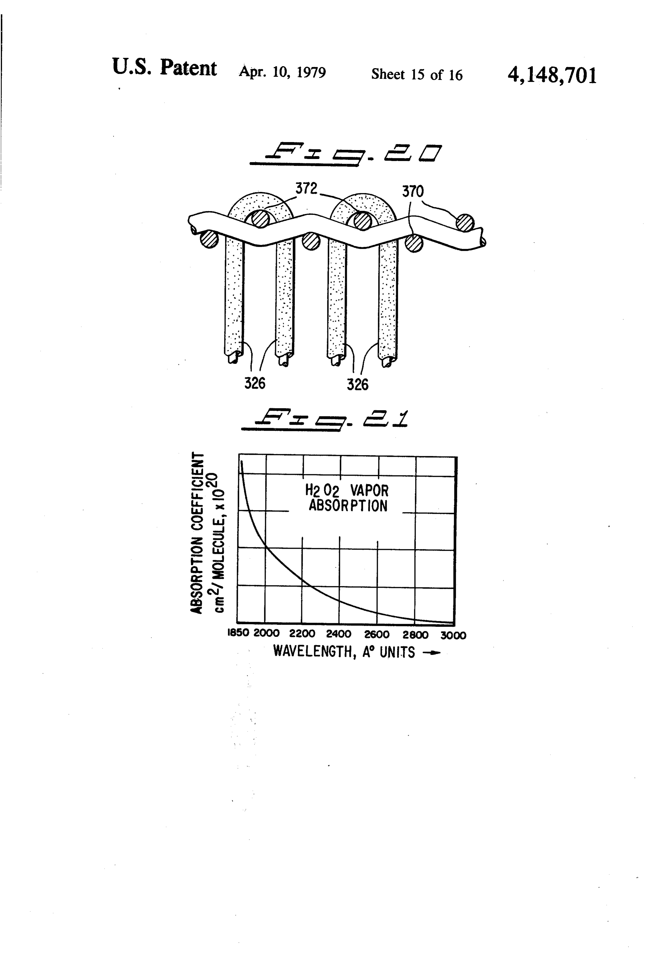
band of the feedstock, such as steam, which is to be FIG. 10 is a plot of the absorption characteristics of acted upon. The heatenergy may be supplied bypassing water vapor versus wave length;
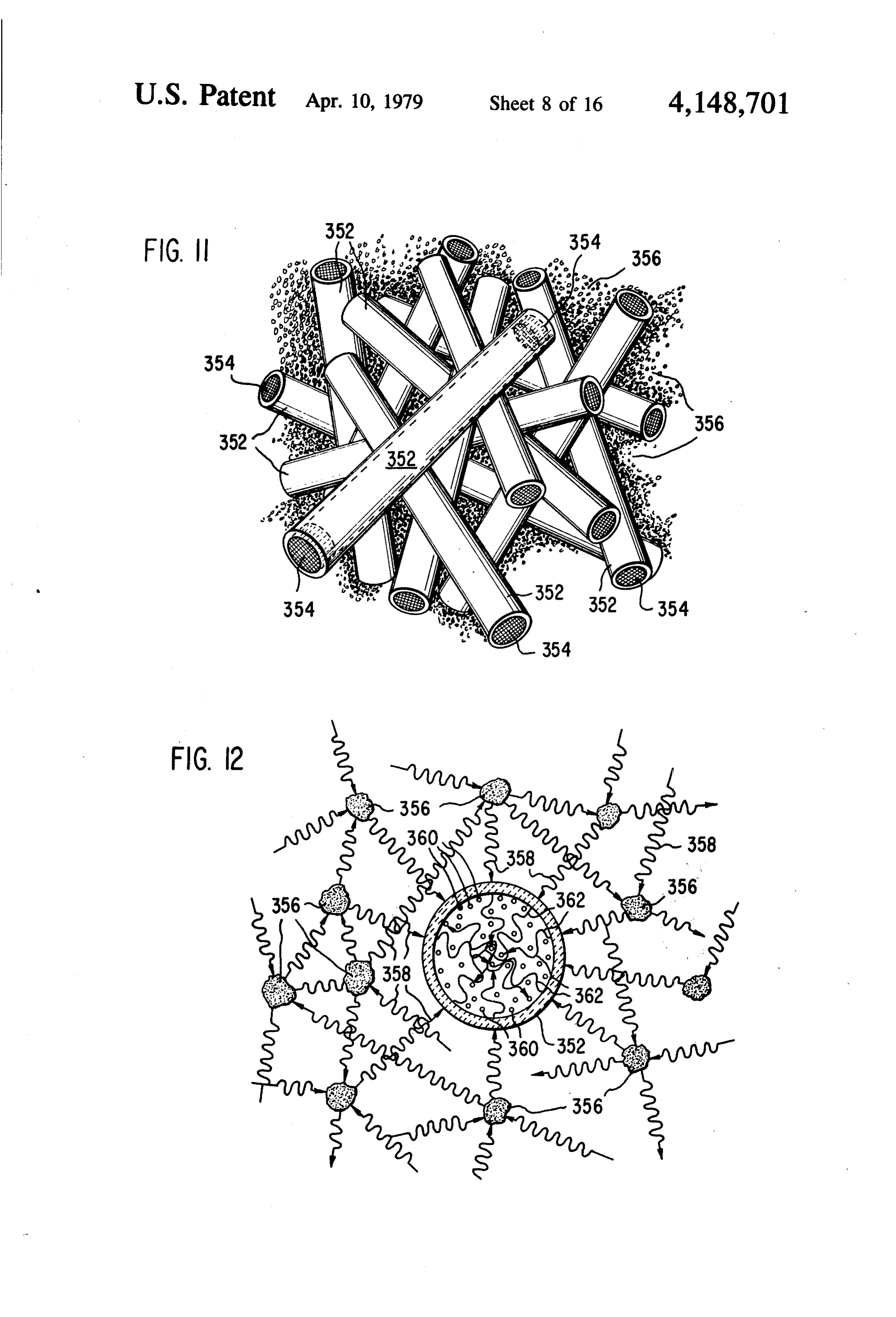
electricity through the coated wires, or by superheating FIG. 11 is a showing of the contents of each of the the incoming feedstock, as desired. reaction chambers employed in the preferred embodi In accordance with a further aspect of the invention, 5 ment of the invention; FIG. 12 is a schematic diagram two or more different output radiation frequencies may indicating the generation of concentrated radiation and be radiated into the reaction chamber, to interact with its application to a feedstock, in accordance with the each other to produce sum and difference frequencies, present invention;
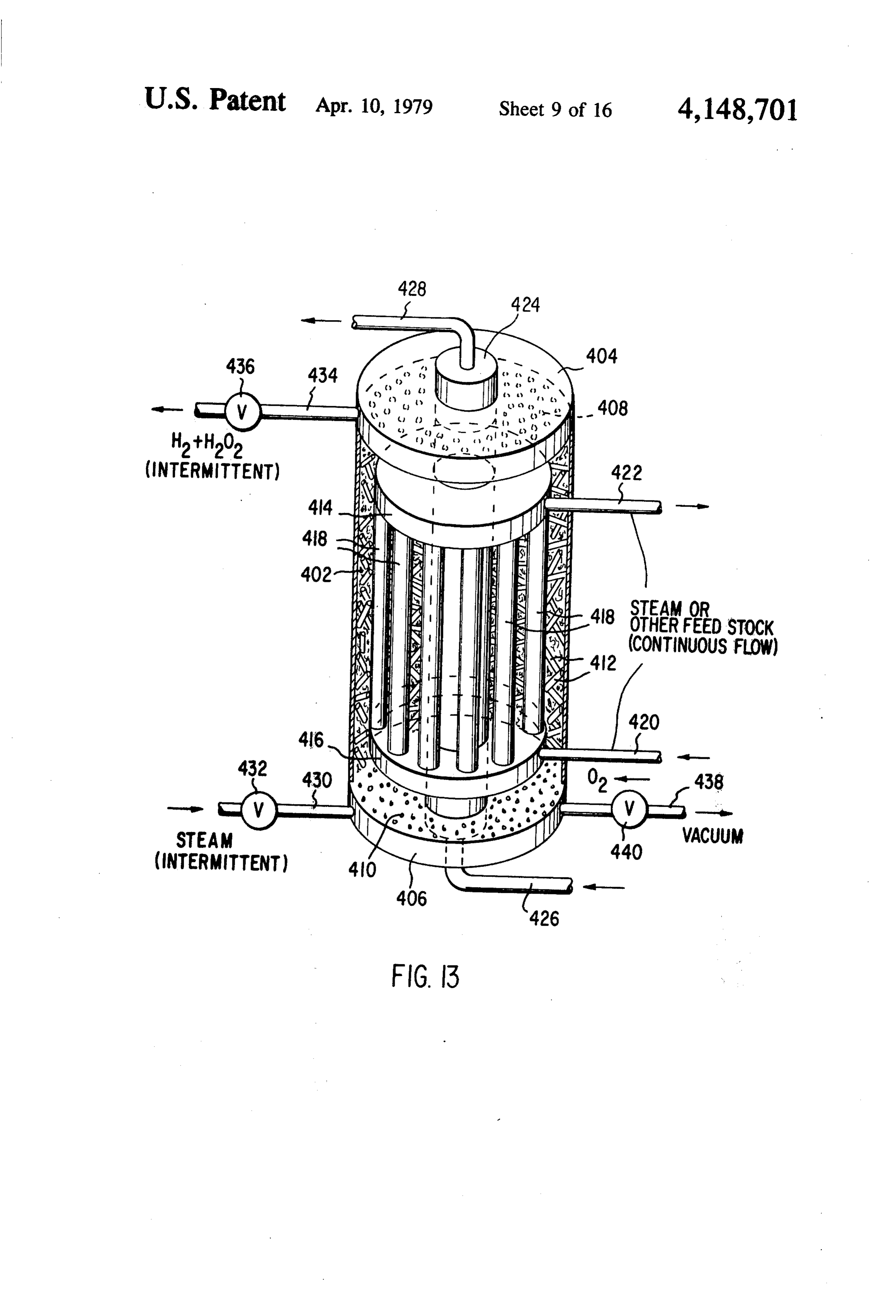
interacting with media discontinuities, thereby provid FIG. 13 shows an alternative apparatus involving the ing the flexibility to "hit' the feedstock with high en 10 continuous flow of feedstock.
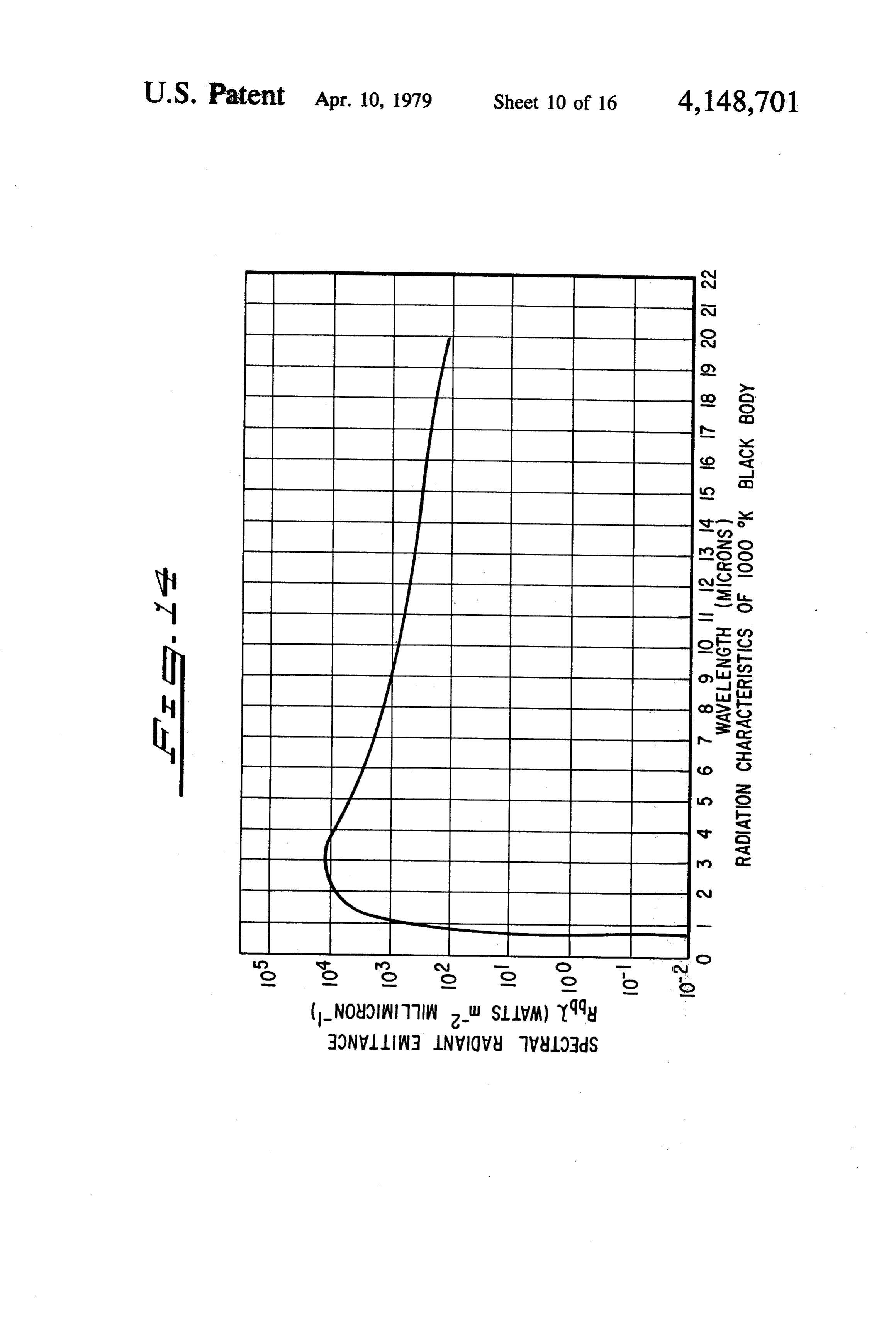
ergy ultraviolet radiation, for example. This is particu FIG. 14 is a plot of Photon Emission from a "Black larly advantageous when the feedstock has absorption Body” at 1000 K. versus Wavelength;
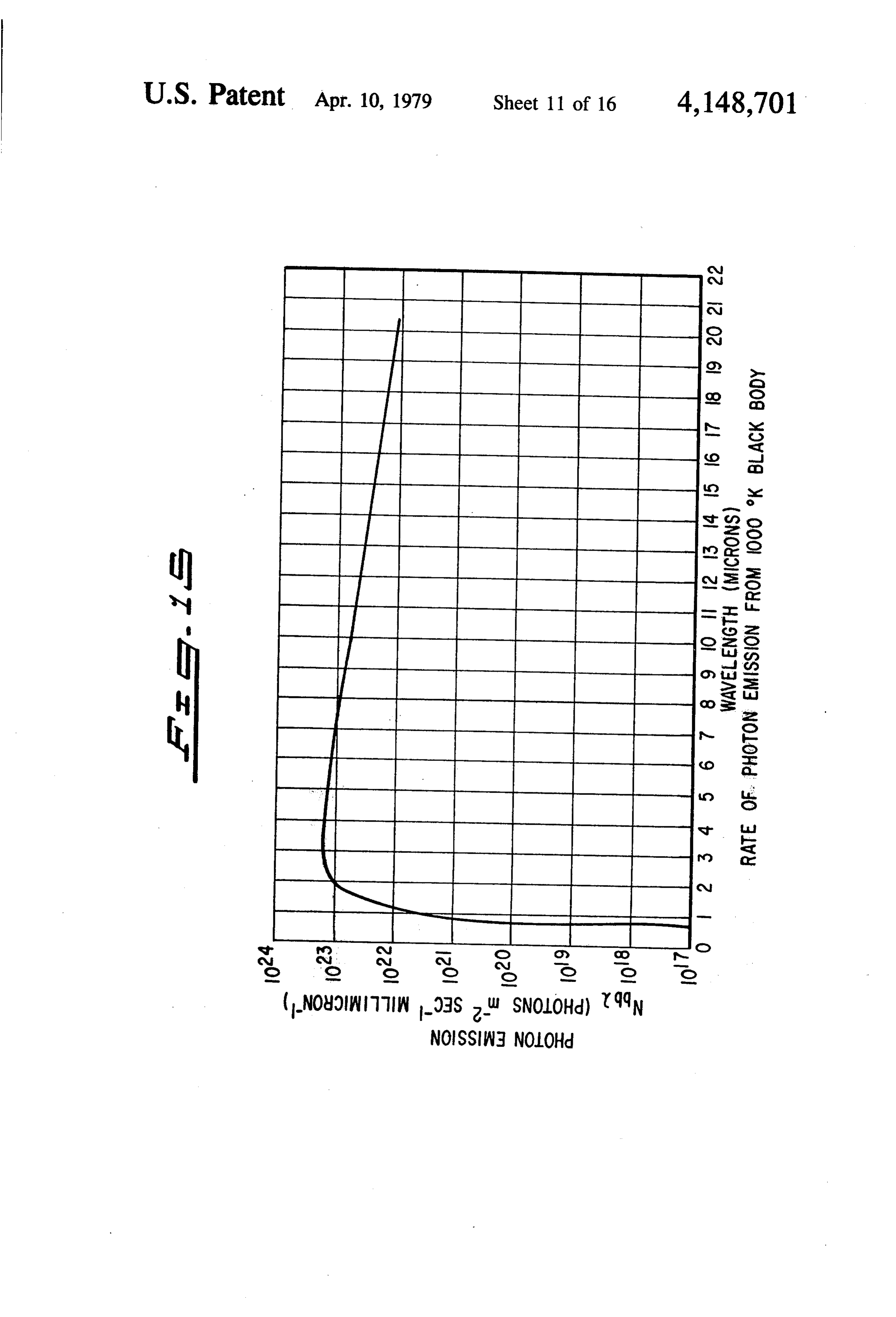
bands in the U. V. frequency spectrum. FIG. 15 is a plot of Radiant Emittance vs. Wave This input radiation to the reaction chamber may be length for a 1000 K. black body;
provided in several different ways. For example, sets of 15 FIG. 16 shows a wire coated with radiation produc differently coated wires having radiation characteristics ing materials;
at different frequencies may be employed; and, alterna FIGS. 17 and 19 show reaction chambers for apply tively, a hollow reaction chamber having highly reflec ing high frequency radiant energy to feedstocks; tive inner walls may be irradiated by two lasers operat FIG. 18 is a diagram showing the reaction chambers ing at different frequencies. In each case the selected 20 of FIG.
FIGS. 17 and 19 included in an operative system;
20 is a detailed showing of one arrangement for feedstock would be fed through the reaction chamber under suitable temperature and pressure conditions and supporting the radiating wires of FIGS. 16, 17 and 19; the output product would be concurrently drawn off. FIG. 21 shows the ultraviolet absorption characteris Again, by matching the radiant energy supplied to the tic of hydrogen peroxide, H2O2; and reaction chamber to the absorption characteristics of 25 FIGS. 22 and 23 are side and sectional views, respec the feedstock, unusually high efficiencies are achieved. tively, of a reaction chamber which is irradiated by light In accordance with a further feature of the invention, from two lasers of different frequencies. the reaction chamber may be divided into input and Initially, before considering the drawings in detail, output sections, with one type of radiation being espe 30 ent relationship the between the subject matter of the pres cially suitable for initial irradiation of the feedstock, and U.S.case and that set forth in my prior copending case, patent application Ser. No. 768,868, filed Feb. 15, another frequency or set of frequencies being applied to the output section, with these latter frequencies being 1977, should be noted in greater detail. Specifically, the selected to avoid adverse effect on the product gases. main difference between the apparatus of the present A feature of the invention involves the introduction invention and that of the prior case is that the special of additional air into the reaction chambers to combine 35 sensitizers and host materials are added in the reaction with the hydrogen which is dissociated from water chambers so as to be directly exposed to the water vapor to produce hydrogen peroxide, with the collat vapor. Additional oxygen may be supplied to the reac eral advantage of supplying heat to the reaction cham tion chamber to facilitate formation of H2O2 in the reac ber from this exothermic reaction. tion chamber, and the withdrawal of the H2O2 with H2 Other objects, features, and advantages of the inven 40 from the reaction chamber.
tion will become apparent from a consideration of the theThe following description of FIGS. 1 through 8 of drawings will closely parallel that set forth in my following detailed description and from the drawings. prior copending U.S. patent application Ser. No. BRIEF SUMMARY OF THE DRAWINGS 767,868. The portion of the detailed specification which FIG. 1 is a schematic representation of an illustrative 45 is more closely related to the new host material and embodiment of the system of the present invention; sensitizer material subject matter, and to the matching FIG. 2 is a perspective view of the hydrogen bur of the reaction characteristics to the absorption versus ner/heating means which may be employed as part of frequency characteristic of the feedstock will be found the system; in that portion of the specification involving the de FIG. 3 is a vertical cross-section of the hydrogen 50 scription of FIGS. 9through 13, and particularly FIGS. burner of FIG. 2; 10 through 13 in the following description. FIG. 4 is a perspective view partially broken away DETAILED DESCRIPTION for illustrative clarity of a reaction chamber used in the Turning now to FIG. 1, the system of the present present system;
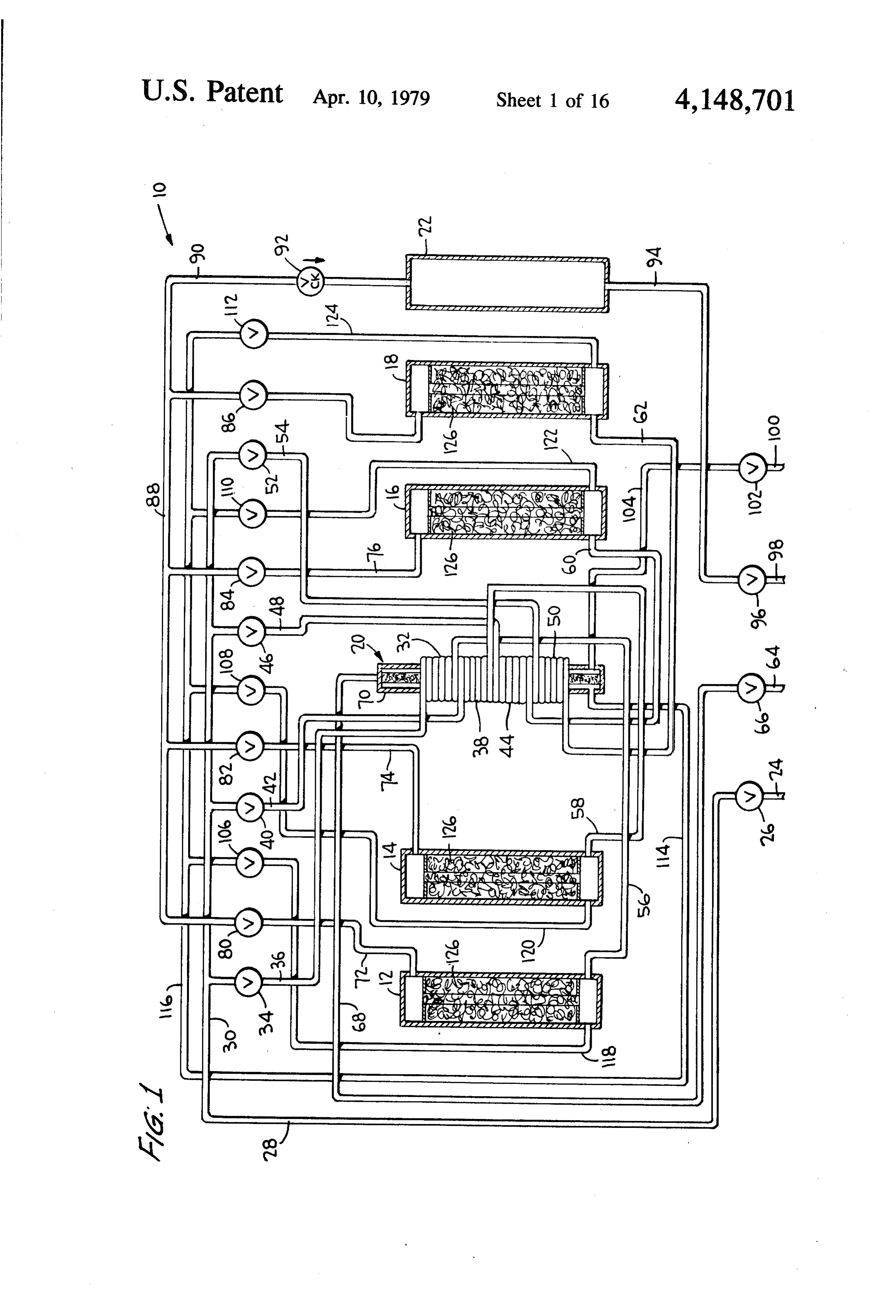
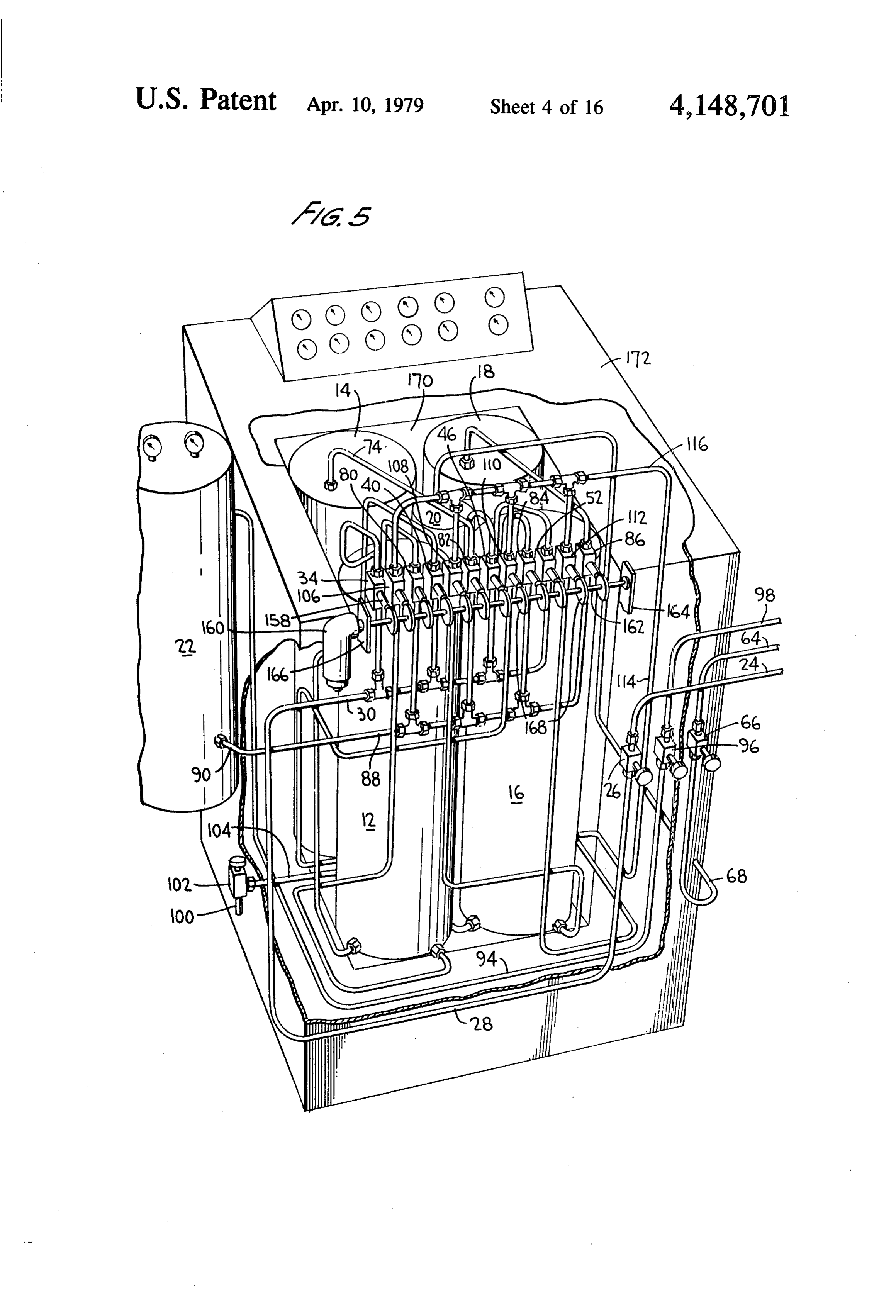
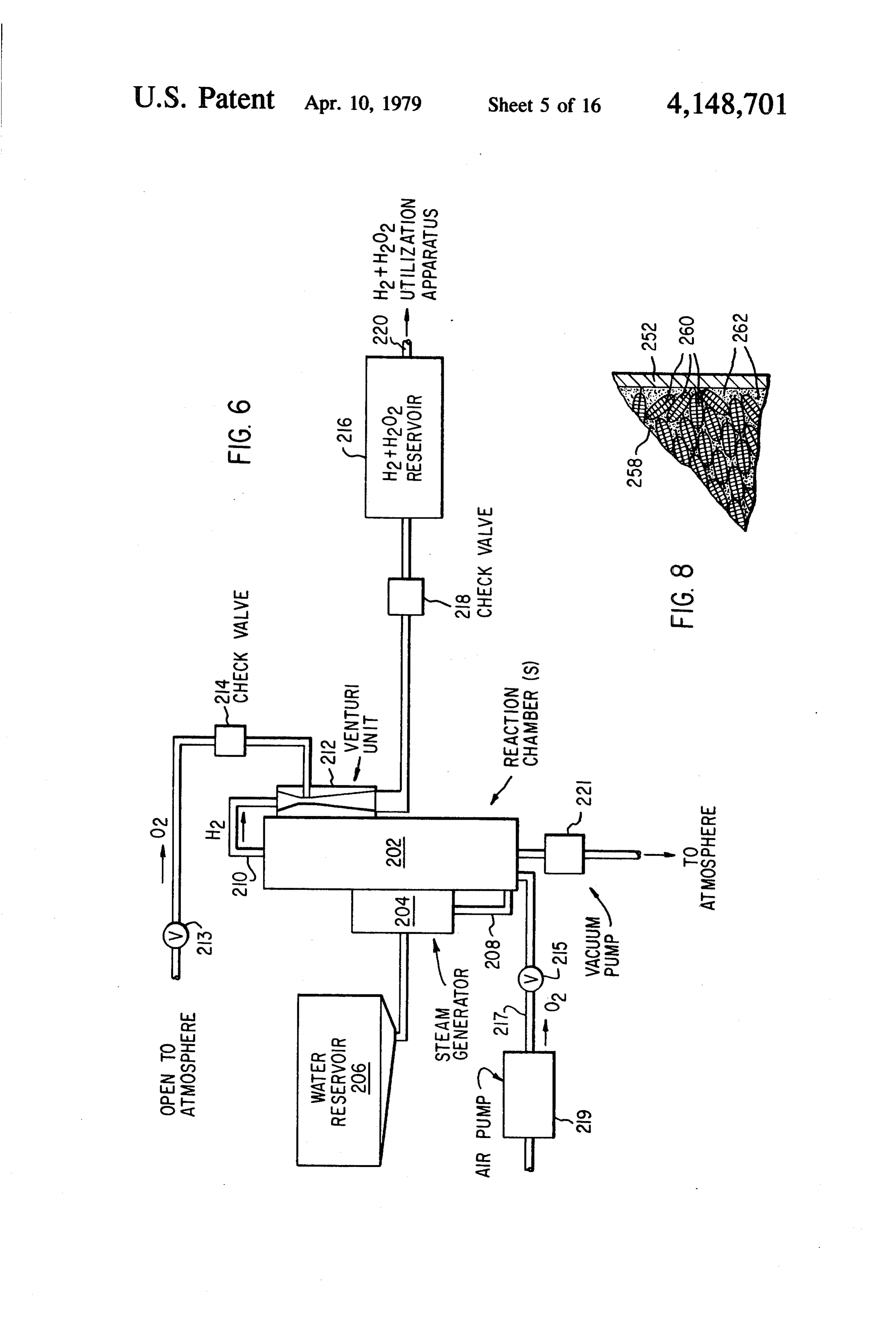
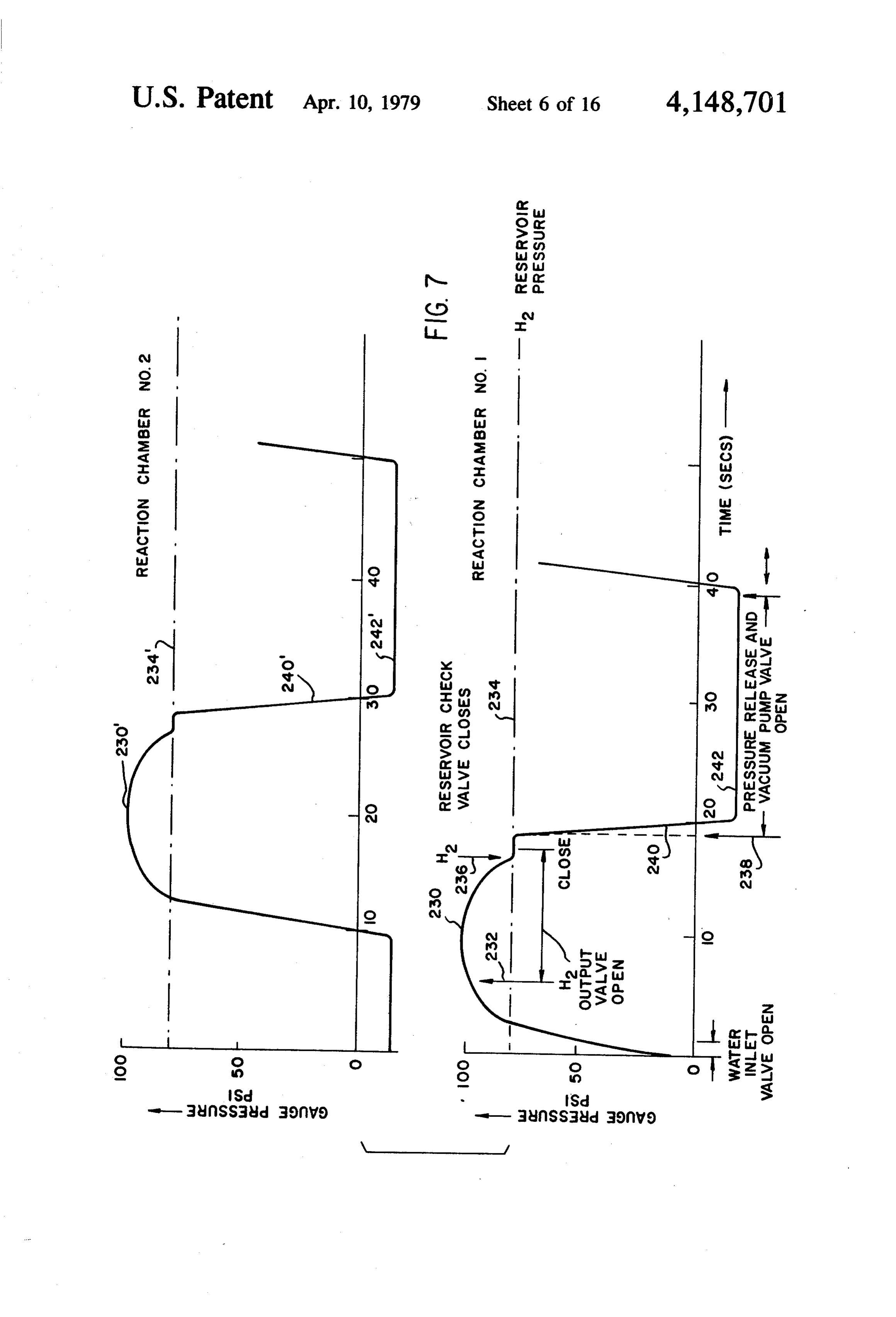
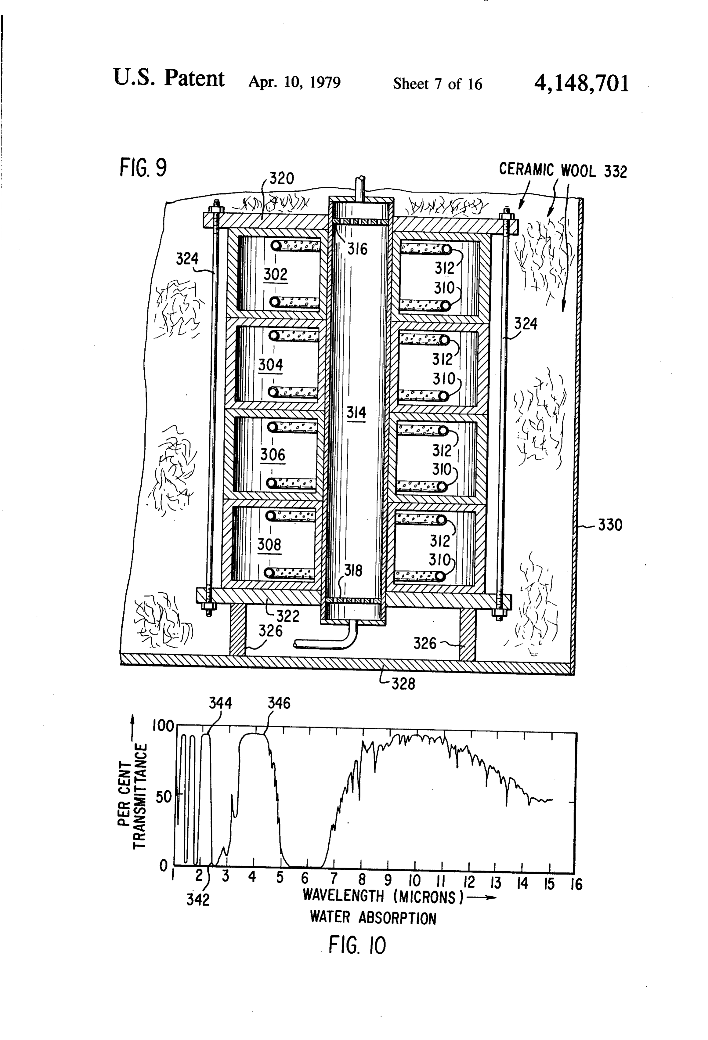
FIG. 5 is a perspective view, also partially broken 55 invention is generally designated by the numeral 10 and away, of a complete system illustrating the principles of it comprises reaction chambers 12, 14, 16 and 18, heat the present invention; ing means generally designated 20, and a hydrogen and FIG. 6 is a block diagram of a system illustrating hydrogen peroxide reservoir or accumulator 22. Water certain principles of the present invention; enters the system at conduit 24, passes through flow FIGL 7 is a pressure versus time plot for a multiple 60 control valve 26 and conduit 28 to manifold 30. Water reaction chamber system of the present invention; may then be supplied to heat exchange coil 32 through FIG. 8 is a cross-sectional view of a portion of a valve 34 and conduit 36, to heat exchange coil 38 reaction chamber assembly which may be employed; through valve 40 and conduit 42, to heat exchange coil FIG. 9 is a schematic diagram of the structural rela 44 through valve 46 and conduit 48, and to heat ex tionship of a plurality of reaction chambers, central 65 change coil 50 through valve 52 and conduit 54. It will burner, and enclosing insulating housing of a preferred be seen that conduit 36 is the inlet end of heat exchange structural arrangement for use in a system of the present coil32, 56 which the outlet of heat exchange coil 32 being conduit is connected to one end of reaction chamber invention;
Page 20
12. Similarly, the outlet end of heat exchange coil 38 is that in event of a "cold' start where there are no hydro conduit 58 connected to one end of reaction chamber gen tailings to be burned, a combustible gas, such as 14, the outlet end of heat exchange coil 44 is connected hydrogen, could be drawn in through conduit 100 and to one end of reaction chamber 16 through conduit 60, valve 102 to provide the initial start-up heat. The burn and the outlet end of heat exchange coil 50 is connected ing of hydrogen in burner 70 provides considerable heat to one end of reaction chamber 18 through conduit 62. which, by radiation and conduction is passed to the Vacuum is applied to the system, for purposes which reaction chambers which are filled with reactant 126. will become apparent as the description proceeds, When the system is pre-heated to a sufficiently high through conduit 64, flow control valve 66, and conduit temperature, we are ready to proceed with the genera 68 which is connected to one end of a conventional gas 10 tion of hydrogen and hydrogen peroxide. burner 70. It will be appreciated that heating means 20 Valve 34 is opened to allow a predetermined amount comprises burner 70 and heat exchange coils 32,38, 44, of water to enter heat exchange coil 32 which is, in and 50, and their respective conduits and valves. essence, a steam generator. The water is "flashed” to As will also become apparent as the description pro steam and delivered through conduit 56 to the inlet end ceeds, hydrogen and hydrogen peroxide generated in 15 of reaction chamber 12. The steam enters reaction the reaction chambers 12, 14, 16, and 18 passes through chamber 12 containing reactant 126 to fill the total void conduits 72, 74, 76 and 78, respectively and valves 80, volume and is constrained in this volume because all 82, 84 and 86, respectively, to manifold 88. The hydro outlet valves are closed. The residence time, or reaction gen and/or hydrogen peroxide then passes through time, may be controlled from a few seconds (typically conduit 90 with check valve 92 to hydrogen accumula 20 about 2 to about 3 seconds) to a rather long time (typi tor 22 where it is then drawn off for use through con cally about 60 seconds), depending on the reactant used, duit 94, flow control valve 96, and conduit 98. Conduit the particulate size, the temperature, and the pressure. 100, flow control valve 102 and conduit 104 are pro vided to allow atmospheric air to enter the system when Valves vacuum 108, 110, and 112 are fully opened to allow the evacuation of all residual gases in the other and if needed, as will be described more fully hereinbe 25 reaction chambers and their respective heat exchangers low.
Before proceeding further with a description of the mined amount of waterbewas and piping. It should noted that since a predeter system, it should be distinctly understood that while the change coil 32, valve 34 wastoopened be passed to heat ex for just a brief example given herein for purely illustrative purposes period and then closed.
includes four reaction chambers, there is, in fact, no 30
Steam having entered and permeated reactant 126 in limit other than practical considerations of size and reaction chamber 12, valve 40 is then opened briefly to weight as to the number of reaction chambers used. In allow a metered fact, the invention could be practiced with as few as one coil 38, with the amountsteam of water into heat exchange generated therein then passing reaction chamber and as many reaction chambers as desired, there being no reason why a bank of dozens or 35 through conduit 58 to reaction chamber 14. Valve 40 is even a hundred reaction chambers could not be used. then closed. The steam which passes into reaction For this reason, applicant is not limiting himself to the chamber reaction 14, as with the steam which had passed into chamber 12, is converted into hydrogen and use of four reaction chambers except for illustrative purposes. Obviously, one skilled in the art would easily /or hydrogen peroxide and then held restrained in the be able to include the necessary valve elements and 40 reaction chamber for the predetermined control time. In the meantime, valve 80 is opened so that the pressure other hardware if he were adding more reaction cham built up in reaction chamber 12 will force the hydrogen bers.
With the foregoing understood, the description of the to exit through conduit 72 and valve 80 into manifold 88 and then through check valve 92 into the hydrogen instant inventive system will proceed. The system runs accumulator 22. Valve 80 is then closed and valve 106 is at about 900 K, or 1000 K. and may be pre-heated by 45 opened to allow the vacuum to empty the residual hy any well-known electrical heating means such as that drogen and oxygen tailings from reaction chamber 12 described in the parent application. Alternatively, pre heating can be accomplished by burning hydrogen in and pass it to burner 70 where the mixture is burned burner 70, the hydrogen being the "tailings' left in one using disproportionated oxygen from reaction cham or more of the reaction chambers from a previous run of 50 bers 12, 16, and 18 along with additional atmospheric the system. For this pre-heating cycle, flow control oxygen supplied through conduit 100, if necessary. It valve 26 is opened to allow water to enter the system should be noted that when valve 80 was opened to pass the hydrogen and/or hydrogen peroxide out of cham filling manifold 30, Valves 34, 40, 46 and 52 remain ber closed during this cycle, Valves 106, 108, 110 and 112 106,12, and then vacuum was applied by opening valve are opened. Vacuum is applied at conduit 64 with valve 55 ated the oxidized reactant in chamber 12 disproportion 66 opened. Thus, it will be seen that vacuum is applied in thetoreaction release the bound oxygen since the temperature chamber remained high and the pressure via conduit 68 to burner 70. Since the other end of burner 70 is connected to conduit 114 which, in turn, is was lowered.
connected to manifold 116, manifold 116 is under vac With valve 106 still open, valve 82 is also opened to uum. Then, since valves 106,108,110, and 112 are open, allow the hydrogen and/or hydrogen peroxide gener the vacuum is applied to reaction chambers 12, 14, 16 ated in reaction chamber 14 to flow into the manifold 88 and 18, respectively, through conduits 118, 120,122 and from which it is directed into the hydrogen reservoir 124, respectively. Thus, any residual hydrogen tailings 22. In the meantime, valve 46 had briefly opened to remaining in any of the reaction chambers is drawn into allow a metered amount of water into heat exchange the inlet end of burner 70 to be burned along with any 65 coil 44 and then the steam formed in heat exchange coil residual oxygen tailings or with atmospheric air drawn 44 passes to the inlet end of reaction chamber 16. At this in through conduit 100 and valve 102 by the vacuum point, valve 84 is still closed. Valves 106 and 112 are still which also affects this air line. It should also be noted open to allow vacuum to exhaust chambers 12 and 18.
Page 21
Valve 82 then closes and valve 108 opens along with course of the second phenomena, to be described in valves 106 and 112 which are also open. Thus, hydro detail below, the H2O molecules are directly dissociated gen and/or hydrogen peroxide and oxygen tailings are by photon energy, forming H2 and also H2O2, hydrogen being conveyed through valve 108 to burner 70 for peroxide.
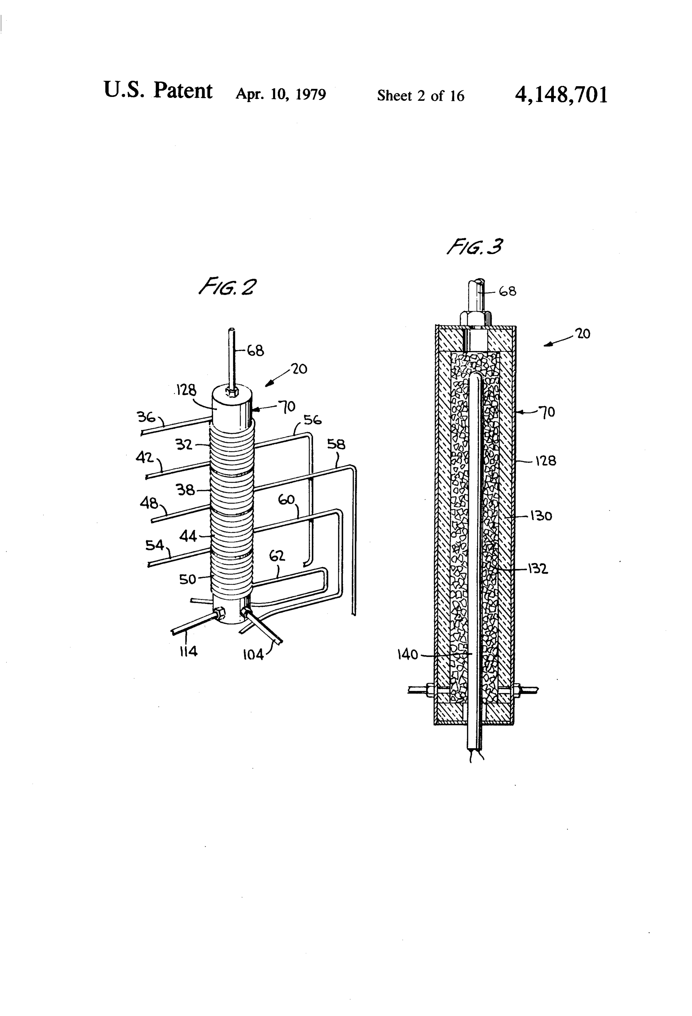
combustion with the combustion gases being exhausted 5 It should also be noted that pressure changes play an through conduit 68. important partin the system. Specifically, the reactantis Then, valve 84 is opened to pass the hydrogen and/or heated to a temperature well above the dissociation hydrogen peroxide from reaction chamber 16 to mani temperature for oxygen from the metallic oxide of fold 88. Valves 106 and 108 are opened to allow vacuum higher oxidation number at room tempeature. This tem to exhaust the respective chambers 12 and 14 while O perature for MnO2 is given in handbooks as 535' C., and valve 52 has been allowed to briefly open to pass a at atmospheric pressure this MnO2 will dissociate to metered amount of water to heat exchange coil 50 with Mn2O3 at temperatures above 535' C. Accordingly, it is the steam being formed then passing to reaction cham desired to operate at temperatures well above 535 C. ber 18. The steam in reaction chamber 18 reacts with such as 600' C. to 950' C. In addition, during the hydro reactant 126 to form hydrogen and/or hydrogen perox 15 gen formation portion of the cycle, the pressure must be ide which is restrained since valve 86 is still closed. well above atmospheric so that the oxygen will be ab Valves 106, 108 and 110 are all open so that the other sorbed by the Mn2O3 (the oxide of lower oxidation reaction chambers are being exhausted. number), with a pressure of about at least 75 psi or 100 Valve 88 is then opened to relieve the pressure on being preferred, and preferably between 100psi and 150 reaction chamber 18 and allow the hydrogen and/or 20 psi to as high as 200 psi or more. In addition, during the hydrogen peroxide to pass to manifold 88. At this point, oxygen disproportionation phase, the free oxygen and the whole cycle starts again and valve 14 is briefly other gases are removed from the vicinity of the reac opened to allow a metered amount of water to pass to tant, preferably by a reduction in pressure to less than heat exchange coil 32, valve 86 is closed, and valve 112 atmospheric, with about one-tenth atmosphere being is opened. The whole cycle then repeats. 25 successfully employed. As can be appreciated, by using While the system of the invention is shown schemati temperatures and pressures well above and below criti cally, it will be readily understood by one skilled in the cal levels during the two phases of the cycle, increased art that it can be easily constructed. The valves are all of speeds of operation may be obtained. a mechanical type which are cam operated so that a Reference is now made to FIGS. 2 and 3 wherein the precise timed sequence of events can be carried out in a 30 heating means 20 is shown in more detail. Heating predetermined manner, the timing of the opening and means 20, as already discussed, comprises burner 70 and closing of the valves being controlled by the size, shape, heat exchange coils 32, 38, 44, and 50. Burner 70 com configuration and speed at which the cams are moving. prises casing 128 made of any suitable metallic material The following "steps" are identifiable in the total lined with a porous fire brick insulation 130 which is reaction cycle involving gases and solids: 35 carved or otherwise formed to fit casing 128 and has an (1) Supply of the water vapor (steam) in the direction axial hollow core running longitudinally through most of flow. of its length. The hollow core is, in turn, filled with a (2) Diffusion of this steam into contact with the suitable surface catalyst 132 for "burning" hydrogen particulates of manganese oxides or to the reacting and oxygen to form steam. Through the center of heat interface which may be on the surface, or inside the 40 ing means 30 is a conventional electrical resistance heat particulate, depending on the oxidation level of that ing element 140 which is used, when necessary, for particular particulate in the gradient (overall). pre-heating the system for a cold start. At the lower end (3) Interface reaction (intrinsic rate), including se of heating means 20 as in the drawings, are atmospheric questering of oxygen and the release of the gaseous air inlet 104 and residual tailings inlet 114. At the upper product Ha. 45 end is exhaust line 68.
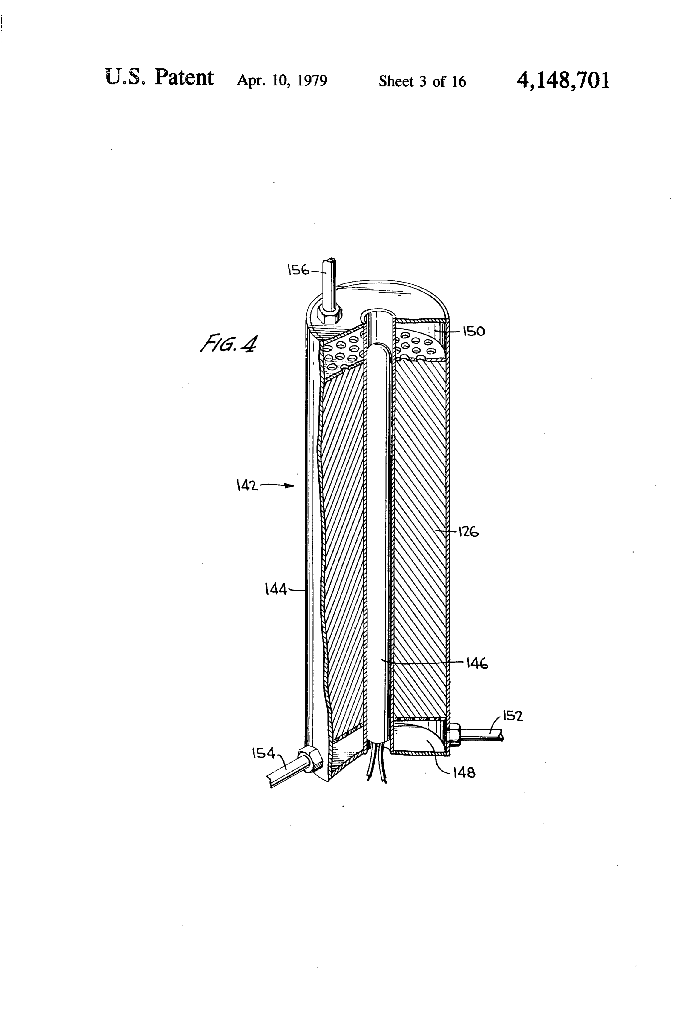
(4) Diffusion of product from the interface. The next sub-system under consideration is the reac (5) Removal of product, Ha, in the direction of flow. tion chambers 12, 14, 16 and 18. For an understanding (6) Concurrently with Steps 2-5, the water vapor is of the construction of the reaction chambers, attention also being directly dissociated by photon action, pro is directed to FIG. 4 where a single reaction chamber ducing both Ha and HaO, as described in detail below. SO designated generally as 142 is shown. Reaction chamber (7) Diffusion of combined oxygen from the interior 142 comprises an outer casing 144 made of any suitable of the reactant to the interface, and then away from the material such as inch thick stainless steel or as dis reactant in the direction of flow of the H2 and O2 cussed in the aforementioned co-pending application. It residual tailings. is filled with reactant 126 as discussed above and as (8) Combustion of the Ha and O, tailings in the 55 shown and described below in connection with FIGS. centrally located burner. 8, 11 and 12. Passing axially through the reactant is a (9) Removal of products of combustion from the conventional electrical resistance heating element 146, burner in its separate direction of flow. this heater being essentially the same as heater 140 in The instant process is a process in which a relatively FIG. 22. This may be used for pre-heat in a cold start. small amount of heat-energy input, (in the form of pre 60 As already discussed, however, the exact means used heat for the reactant) provides conditions for the reac for pre-heating the system is not critical to the invention tant to effect changes of state, during which a gaseous and any means well-known in the art for accomplishing chemical molecule is completely dissociated into its this end may be used. The reactant 126, including sensi separate gaseous atoms by two distinct phenomena. In tizer and host materials, is placed in casing 144 leaving the course of one of these phenomena, the solid reactant 65 a space at each end, these spaces being designated in concurrently effects a "change of state' by means of an FIG. 23 as 148 and 150. Spaces 148 and 150 essentially exothermic transformation from one oxidation product serve the function of surge tanks, manifolds, or the like. level to another oxidation product level; and in the Steam inlet. 152 and vacuum inlet 154 are provided at
Page 22
one end of reaction chamber 142 and hydrogen outlet entire assembly, including the venturi unit 212, may be 156 is provided at the other end. Steam inlet 152 corre in the order of 600' to 950 C.
sponds to conduit 56, for instance, vacuum outlet 154 Hydrogen peroxide may be formed in either of two corresponds to conduit 118, for instance, and hydrogen ways, and the proportion of hydrogen peroxide to hy outlet 156 corresponds to conduit 72, for instance, in drogen gas may be controlled by valves 213 and 215. FIG. 1. Initially, considering the formation of H2O, within the Turning now to FIG. 5, the preferred configuration reactor chambers, by photon action, valving 215 would of the apparatus is shown along with the sub-system be opened while steam is present in the reaction cham which includes the valves and driving mechanism for bers and while the H2 gas is being drawn off, and oxy the same as well as the "plumbing'. It will be seen that 10 gen at high pressure, corresponding to the pressure of the valves which are described above are arrayed in a the reaction chamber is admitted to chambers 202 via single line. The valves are of a conventional type which conduit 217 from pump 219.
are operated by pushing or releasing a plunger desig Now considering the subsequent formation of H2O2, nated, for convenience of illustration, as 158 in conjunc valve 215 would be permanently closed, and valve 213 tion with valve 34. It will be appreciated that while the 15 would be open. When hydrogen starts to flow rapidly description of the valves refers to valve 34 and plunger through the venturi unit 212 the check valve 214 will 158 for exemplary purposes, each of the valves operates open and oxygen will be combined with hydrogen to in the same manner. A variable speed motor 160 turns a form hydrogen peroxide. This combination of hydrogen drive shaft 162 which is journaled in mounting plates 20 with oxygen is an exothermic reaction as set forth quan 164 and 166. Fixedly mounted on drive shaft 162 are titatively in equation form hereinbelow. The hydrogen cams 168, with one cam corresponding to each of the and hydrogen peroxide is stored in reservoir 216, which valves and mounted on drive shaft 162 in such a way as is maintained at a relatively high pressure level by the to cooperate with plunger 158 of each valve. Thus, as check valve 218 which prevents loss of hydrogen back motor 60 turns drive shaft 162 and, in turn, cams 168, toward the reaction chamber 202 between the intermit the valves are opened and closed in a manner which is 25 tent withdrawing of hydrogen from the reaction cham predetermined by the positioning of cams 168. This, of ber 202. Hydrogen and hydrogen peroxide may be course, will be readily understood by one skilled in the withdrawn as needed from the resorvoir 216through an art. output line 220. By closing both valve 213 and valving Referring further to FIG. 5, it will be seen that the 30 215, the amount of hydrogen peroxide which is gener reaction chambers are set vertically in an enclosure that atedhydrogen, is severely limited, and the bulk of the output will is square in cross-section and are shown in the drawing beVacuum rather than H2O2. pump 221 may be employed to speed up with reaction chamber 12 in the front left-hand corner, separation of oxygen, hydrogen tailings, and other re reaction chamber 14 in the rear left-hand corner, reac tion chamber 16 in the front right-hand corner, and 35 disproportionation. reactant during dissociation or sidual gases from the reaction chamber 18 in the rear right-hand corner. with regard to the block diagram of FIG. 6, it is to be Heating means 20 is disposed in the center. The enclo understood that the components shown in this figure sure or, more specifically, inner enclosure 170 is prefer may be employed ably made of magnesium oxide packed in a stainless scribed hereinaboveininconnection with any system de the present specification. Specif steel container. This material was chosen because it distributes heat evenly throughout the volume of the been, ically, the various input and output control valves have enclosure 170. Surrounding inner enclosure 170 is outer poses for the most part, omitted from FIG. 25 for pur of simplicity. Similarly, the precise physical ar enclosure 172 which is made of any suitable material rangement, with the units 202,204 and 212, for example, such as stainless steel and filled with a high quality insulation such as alumina fibers. It will be appreciated 45 being in intimate heat-conducting relationship with each other, and insulated from the atmosphere, is not by one skilled in the art that any high quality, high shown in FIG. 25, but may be in accordance with dis temperature, insulating material may be used.
Returning to a consideration of the drawings, FIG. 6 tion. of other units disclosed in the present specifica closures is a block schematic drawing showing in a central posi FIG. 7 shows a typical pressure versus time cycle for tion the reaction chamber or chambers 202 and an im SO a system in accordance with the present invention using mediately associated steam generator 204. A reservoir manganese oxide as the reactant, and four reaction of water 206 supplies water to the steam generator 204, chambers, This is, for example, of the type described which may be of any of the types described in connec hereinabove in connection with FIGS. 1 through 5 of tion with earlier figures of the drawings. In this connec the drawings.
tion, it may be noted that all of the arrangements shown 55 The pressure is "gauge' pressure in pounds per in F.G. 6 are applicable to the hydrogen generation square inch (psi). With this pressure scale, atmospheric apparatus shown hereinabove in the present specifica pressure is of course indicated by zero. tion.
Steam or water vapor is supplied to the reaction overall Considering the cycles shown in FIG. 26 from an chamber or chambers 202 through line 208 which may chamberstandpoint, including the complete cycle for each reaction both breaking up the water vapor of course be internally connected between the immedi and dissociating the oxygen from the reactant may be 40 ately adjacent and thermally connected units 202 and seconds. However, the cycles of the reaction chambers 204. Hydrogen from reaction chamber or chambers 202 are evenly staggered in operation, by 10 seconds in the may be routed through output line 210 to the venturi example so that hydrogen is generated on a substantially tube combining unit 212 which is also in intimate heat 65 continuous basis. In FIG. 26 the pressure cycle for conducting relationship with reaction chamber 202 and reaction chamber No. 1 is shown in the lower charac the steam generator 204. As mentioned above, in con teristic, and the pressure cycle for reaction chamber No. nection with manganese oxide the temperature of the 2 is shown in the upper characteristic. The pressure
Page 23
versus time characteristics for reaction chambers Nos. 3 and 312 to supply gases to the reaction chambes's and to and 4 are substantially the same as those of chambers remove gases therefrom. These input and output mani Nos. 1 and 2, but are displaced by additional 10 second folds serve the same functions as the spaces 148 and 150 intervals. at the top and bottom of the cylindrical reaction cham Now, referring specifically to the lower characteris 5 bers as shown in FIG. 4, for example. tic 230 in FIG. 7, the cycle starts with the opening of Each of the reaction chambers 302,304,306, and 308 the water inlet valve for a couple of seconds at the contain reactant, such as manganese oxide, and voids beginning of the cycle. Steam is promptly generated created by wire mesh cells as described above, or other and fills the first reaction chamber. At about 6 seconds, structure which will be described below, with which the hydrogen outlet output valve is opened as indicated 10 the sensitizer and host materials are associated. by arrow 232. Hydrogen and/or H2O, continues to flow A burner 314 extends through the central opening of until about 16 or 17 seconds of the cycle, when the all of the four donut-shaped reaction chambers. The hydrogen pressure drops to the hydrogen reservoir burner 314 has the general configuration shown in FIG. pressure, indicated as equal to 80 pounds by the dash 3, but is provided with upper and lower apertured plates dot line 234 in FIG. 26. The closure of the hydrogen 15 316 and 318 for ease in applying the hydrogen and oxy reservoir check valve 218, as shown in FIG. 25, is indi gen to the burner and for ease of withdrawing the cated by the arrow 236 in FIG. 7. Soon after the closure burned gaseous products from the unit. Although the of check valve 236 the pressure release and vacuum details of the burner 314 are not shown, it includes the pump valve is opened, as indicated by arrow 238 and refractory lining and the granular refractory material the pressure drops along characteristic 240 to the nega 20 such as is shown at 130 and 132, respectively, in FIG. 3. The unit of FIG. 9 is also provided with heavy upper tive pressure of about one-tenth of an atmosphere indi cated by line 242. During the interval from about 20 and lower plates 320 and 322, which are bolted together seconds to 40 seconds the disproportionation phase with a series of bolts 324 spaced around the periphery of takes place. Then at approximately 40 seconds the the plates 320 and 322. With this arrangement the reac water inlet valve is opened again, and the cycle repeats. 25 tion chambers 302, 304, 306, and 308 are rigidly held The upper characteristic in FIG. 7 shows the same can together in intimate heat conducting relationship, and withstand very high pressures even at very high cycle for reaction chamber No. 2 as described above for temperatures reaction chamber No. 1. In the upper characteristic the bers. with deformation of the reaction cham same reference numerals are employed, but primes are employed in place of the unprimed numbers used in 30 suitable The reaction chamber assembly is mounted on any connection with the lower plot of FIG. 7. insulating support as indicated by the blocks FIG. 8 is a fragmentary view of a portion of a reac 326. A lower metal base 328 and lighter gauge stainless tion chamber such as that shown in FIGS. 1 and 4 de steel metal sidewalls 330 are also provided. High tem scribed hereinabove. In FIG. 8 the outer cylindrical perature heat insulating ceramic wool encloses the reac wall 252 may for example be made of one-quarter or 35 tion chamber assembly and reduces heat radiation to three-eighths inch stainless steel. very low levels. The ceramic wool is indicated by refer Referring more specifically to FIG. 8, in order to ence numeral 332 in FIG. 9. In passing, it may be noted expose the manganese oxide powder fully to the space that the use of flat donut-shaped reaction chambers within reaction chamber 258, this chamber is filled with provides a geometry which is superior to the set of five a large number of hollow stainless steel screen elements 40 cylinders shown in FIG. 5, in that the reaction cham which may be formed by taking small strips of stainless bers are in more intimate heat conducting association steel and folding them over upon themselves and weld with one another and with the central burner, than in ing or otherwise securing them together to form a hol theApart arrangement of FIG. 5.
from the physical arrangement of the four low enclosed space. The chamber 258 is initially filled with these stainless steel, hollow mesh cells 260. Then a 45 reaction chambers and the central burner, the "plumb large quantity of manganese oxide is poured into the ing' and mode of operation of the system as described reaction chambers and is shaken down in among the in connection with FIGS. 1 through 8, remains un stainless steel mesh cells to completely fill the entire changed.
chamber 258. In FIG. 8 a number of these stainless steel A more detailed consideration of the absorption char mesh cells designated 560 are shown, and the manga 50 acteristic of water vapor and other possible feedstocks, nese oxide powder 262 between the cells is also indi and the matching of the host and sensitizer materials to cated. It is to be understood, of course, that other tech the feedstock absorption characteristic will now be niques may be employed for exposing the reactant to undertaken.
the space within the reaction chamber, but the forego 55 ofInwater FIG. 10 the relative transmittance and absorption vapor at different wavelengths is shown. By ing system has proved eminently satisfactory in at least one 4-reaction chamber apparatus which has been suc way of example, note that at wavelengths of about 2.5 cessfully operated. to 2.6 microns, the curve which represents transmit In addition, the host and sensitizer material may be tance has a dip designated 342 in FIG. 10. This is in included in the fabrication of the wire mesh cells 260. contrast to the peaks 344 and 346 which are centered With water vapor within these wire mesh cells, this 60 just above 2 microns, and in the vicinity of 4 microns, feedstock is fully exposed to the intense radiation from respectively. A combined host material and sensitizer the sensitizer. which will provide intense coherent radiation in the FIG. 9 shows an improved structural arrangement of vicinity of 2.5 and 2.6 microns, and which absorbs en the reaction chambers in which the four reaction cham ergy in the vicinity of 1.2 to 1.3 microns, will be em bers 302, 304, 306 and 308 are donut-shaped and are 65 ployed as one set of materials for concentrating energy stacked up on top of one another in intimate heat con and applying it to water vapor. The particular host ducting and transferring relationship. Each of the four material and sensitizer which provides this wavelength reaction chambers is provided with two manifolds 310 of absorbing heat energy and radiating energy is cal
Page 24
cium fluoride CaF2 as the host material, and uranium-3 bility of getting 1.7ev (or greater) electronic excitations as the sensitizer. by the cumulative action of phonons. Before considering FIGS. 11 and 12 some back The thermal radiations from real solids cannot exceed ground relative to the phenomena which are taking the emission which would be obtained from a perfect place will now be included. black body at the given temperature and frequency. Initially, it may be noted that the theory of Masers Most solids emit somewhat less thermal radiation than and Lasers of course forms a background for the present the maximum which is expressed by:
invention. The word "LASER' is an acronym which stands for the Light Amplification by the Stimulated Pv =8 rh v3C-3 (Eh V/kT-1)-leg cm-2 sec-1 (50) Emission of Radiation. Although related to some extent 10 to Maser and Laser theory, the present invention does The peak wavelength Apk of the broad emission band not involve the intense collimated beams of energy of black body radiation is inversely proportional to T, characteristic of Masers and Lasers; and of course, Ma according to WIEN'S displacement.
sers and Lasers do not derive their energy from a heat reservoir made up of a body of material at elevated 15 Apk = 0.29T cm = 2.7 x 10⁷T-1A (51) temperatures.
Types of Radiation The TOTAL THERMAL EMISSIVE POWER PT of a perfect blackbody increases as T, according to the
There are two separate processes by which a material STEFAN-BOLTZMANN LAW:
can become a generator (or producer) or radiation en 20 ergy after absorbing suitable quantities of primary en Pr= 2 kT/15C2h. = 5.7 x 10-Terg ergy. In the first process the absorbed energy is con cm-2sec (52) verted (degraded) into a low-quantum-energy heat that diffuses through the material which then emits radiation At room temperature (about 200 K), Apkis in the far called thermal radiation. 25 infrared at 97,000 A, and PT is only 4.6 x 10⁵erg cm-2 In the second process an appreciable part of the ab sec , so that there is not an appreciable amount of sorbed energy is temporarily localized as relatively radiation in the VISIBLE region between 4000 and high-quantum-energy excitation of atoms or small 7000 A.
groups of atoms which then emit radiation called lumi At the temperature of an incandescent lamp filament nescense radiation. 30 (about 2800 K.), Apk is about 10,000 A, and PT is 3.5 x Specifically, "luminescense" is a process whereby 109 erg cm-2 sec, so that there is an appreciable matter generates nonthermal radiation which is charac emission in the visible part of the spectrum. In the tem teristic of the materials involved and not the tempera perature range between about 700 and 1000 K. there is tures. Sometimes, however, the radiation as generated is an overlapping offeeble luminiscence and feeble incan also called "luminescence'. It is in fact luminescense 35 descence.
only when the radiated energy is in excess of the ther The present invention involves temperatures from a mal radiation produced by heat. lower limit of about 900' to 1000' Kelvin or about 600 Thermal radiation from solids is generally a broad to 700 Centigrade and ranges upward from these tem continuous spectrum of radiation, especially infrared, peratures with the upper limit controlled only by the which is emitted in increasing amount as the tempera strengths of the materials utilized (1) as the reactant or ture of the solid is increased.
The quality and quantity of thermal radiation depend host/sensitizer, (2) for the reaction chamber, and (3) for the tanks, tubing, etc.
almost exclusively on the temperature rather than the nature of the emitting solid material. Broadly and objec The Haser Concept tively speaking, luminescence describes emission of 45 The Maser/Laser type of acronym may also be ap radiation (of subatomic origin) in excess of thermal plied to another system termed "Haser', an acronym radiation; that is, luminescence yields photon emission for "Heat Amplification by Stimulated Emission of in excess of the photon emission produced entirely by Radiation.” As will be developed below, however, the thermal agitation. term "Amplification' is not used in the sense of increas Luminescence is generally excited by primary pho 50 ing signal strength, but in the sense of amplifying the tons or charged material particles having individual effectiveness of heat energy.
energies ranging from about 2 ev to over 109 ev and The Haser application depends not as much on coher affords emitted photons with energies in excess of 1 ev. ence or monochromaticity per se, but rather on the When luminescence is excited by energy liberated dur unprecedented energy per unit area. This radiated en ing chemical reactions, the liberated energy per emit ergy is a by-product
of the coherence of the radiation, ting atom or molecule usually exceeds 1 ev. These exci and can be many orders of magnitude greater in energy tation energies are hundreds to millions of times greater than the energies of individual phonons in solids. A than normal incoherent thermal radiation. To under stand why this is possible, it is necessary to review single phonon can increase the energy of an electron or briefly a few of the basic differences between the inco atom in a solid by at most a few hundredths of an elec herent radiation produced by an ordinary bright source tron volt, whereas the individual primary particles nor mally used to excite luminescence can provide energy and the coherent light (radiation) produced by a laser or increases up to the total amount of energy carried by laser, the primary particle (except for rest-mass energy), that In a conventional source the atoms of a solid (or a is, tens to millions of electron volts, gas) are agitated either thermally or electrically to In order to obtain barely visible emissions of thermal higher energy states. When these atoms return sponta radiation from a solid, the temperature of the solid must neously to their lower levels, they radiate some of their be raised above 900 K. to obtain an appreciable proba excess energy as light. Since each atom behaves inde
Page 25
pendently at this state, its emission is at a random time This new system utilizes fine (small) particulates of and in a random direction with a random polarization. solids comprised of oxides which are predetermined by It follows that the light radiated in a single direction design within which some of the host atoms are re is the complex sum of all the light from the individual placed by other frequency sensitive atoms also prede atoms. The phases of any two atoms will tend to cancel termined by design, which, provide stimulated absorp their radiation in some directions and enhance it in tion and emission at predetermined wavelengths. others. The total energy of the source will be on the An ohmic (or other) pre-heat provides to the heat average be radiated uniformly in all accessible direc reservoir mass the original energy to liberate a massive tions, and the amount of energy observed in a given volume of photons at the frequency range which will direction will be proportional to the solid angle sub 10 activate the sensitive atoms included in the host com tended by the observing device. In the Haser interior pound; the fine multi-faceted particulates absorb the the observing device is either a water-vapor molecule photons which normally proceed as phonons through (or other feedstock) or another particulate of reactant. the particulate to generate and provide large numbers of The maximum total energy that can be radiated by a 5 cavity resonances which stimulates emission with each given source depends on two factors: the surface area of internal excursion; therefore, again, the gain by this the source and the maximum temperature to which the regenerative amplifier when driven by the thermal source has been heated. Therefore, in practice, the only cant, noise fluctuations from the cavity walls, can be signifi way to increase the power output from an ordinary source beyond the limitations imposed by the source 20 radiation In the case of the HASER, the principle emissions of material is to increase the surface area of the source. designed and produced to dissociate the chem Power output, however, is only half the solution. ical product may be emitted from the woven wire mesh Concentrated power is much more important than cavity balls or cells 260 (FIG. 8) that fill the entire power itself. A 40-watt fluorescent lamp, for example, Haser cavity.
produces more light than a 40-watt incandescent lamp, 25 (through"preheat'
The energy can be electrical and inserted but the fluorescent lamp is not nearly as effective as the the heaters may alsoheaters) resistance
into the internal cavity or external to the cavity and heat incandescent light source for a spotlight. the mass by conduction and radiation through solids. Now, in a laser or maser, the energy is also emitted Also, the "preheat' energy may be inserted by com when atoms drop from a higher energy level to a lower busting suitable fuels such as hydrogen, hydrogen one; however, in this case the atoms are triggered and 30 oxide, alcohol, and other hydrocarbons, directly inper the emit radiation (to a large percentage) in unison. In the internal cavity of the unit or within a "center-core' case of the Haser, the atoms are triggered to emit radia burning unit as is designed into the unit of FIG. 9, for tion in unison by phonon/photon waves within the unit example.
cavity or cell interior. Enough of the energy previously As the reactive mass reaches temperature levels generated is retained within the mass of particulates to 35 which maintain emission in a compatible phase, polarization level ofexcite the molecules and atoms to a radiating energy, phonons and photons evolve which and direction. This phonon wave interacts with the distribute the thermal energy within the mass. Inciden excited atoms and causes them (to a large degree) to emit their excess energy in phase with the stimulating tally, relative to the use of the terms "photon” and "phonon', when a phonon traveling through space wave before they have a chance to do it randomly. 40 impinges on a solid, the resultant wave in the solid is As a result, the Haser generates a good percentage of termed a "phonon'.
its radiated energy so that it travels in synchronism with the standing phonon waves, therefore concentrating the theThe ability of 'atoms' to store energy has to do with electrons within the individual atoms. The electrons energy emitted as photons. exist as a cloud of negative charge around the positively In effect, the radiated photons from the Haser partic 45 charged nucleus. Each election occupies a state of en ulates are all relatively concentrated, monochromatic, ergy and angular momentum that cannot be occupied and therefore, relatively coherent energy sources. This by any other election.
results in an excellent energy density even though the Therefore, the electrons tend to fill stable shells sur photons are traveling in practically an infinite number rounding the nucleus.
of directions, due to the fact that the particulate sources 50 The electrons of the outermost shell are the ones most number in hundreds of millions. The photons moving easily affected by outside forces because of their acces from particulate to particulate impact and are absorbed sibility. These outer electrons can be moved to higher by other particulates. Then, this STORAGE, BUILD energy states, but they always tend to return to their UP, AND RELEASE of the "phase and amplitude of lowest energy state: the ground state. Electrons at cer radiated energy,” combined with the fine particulate 55 tain levels decay (fall to a lower state) more easily than geometry of the Haser power (energy) source, which electrons at other levels.
provides surface area to emit photons in extremes, al Each excited electronic state of the atom has a char lows a "maximum efficiency utilization' of the radiated acteristic lifetime that indicates the average time it takes energy within the Haser cavity. an electron to fall to a lower level and therefore radiate The act of controlling the spectral emissions to most a photon. Most excited states have lifetimes of about effectively dissociate (for example) water vapor, by 10-8 second.
sensitizing the host compound properly is another very There are some excited states or levels in all atoms in important point. The monochromatic waves may be which the electron cannot decay easily by giving up a come distorted in passing through substances, so that photon. Such atoms must therefore wait for other harmonic waves are generated at two or more times 65 means of giving up their energy, such as colliding with their original frequency. other atoms or with the walls of the system. Electrons Infrared wavelengths may be converted into visible in this state of energy tend to stay there for relatively light, and visible light into ultraviolet waves. long periods of time (0.001 second or more), and are
Page 26
referred to as being in metastable states. This is an im In the chemical laser, atomic species such as hydrogen portant part of the storing of energy, which can then be and fluorine can be reacted to produce molecules in an retrieved in the excitation process by stimulation. excited vibrational state which in turn yields amplifica The normal radiative decay from a higher electronic tion or oscillation.
state to a lower one is termed spontaneous emission. As An entirely new excitation process was announced by discussed earlier, processes exist that can force an Garry in 1970. In this, the gas dynamic laser, an appro atomic electron to a higher state or stimulate it to jump priate fuel is burned to produce carbon dioxide and to a lower state. An example of forcing, as discussed nitrogen at high temperature and pressure. When re earlier, is provided when a photon collides with an atom leased through a nozzle into the optical resonator re and excites the outer electron to a higher level, which 10 gion, the gas cools rapidly in terms of its kinetic or can happen when the energy or wavelength of the pho translational energy, but the population of the vibra ton corresponds exactly to the difference in energy tional energy levels of the carbon dioxide molecules between the state the electron is in and some higher becomes inverted since the lower level of the laser possible state. This process is known as absorption be transition relaxes more rapidly. In addition, the vibra cause the photon (energy) is actually absorbed by the 15 tionally excited nitrogen molecules are in near reso atom and all the photon's energy goes into raising the nance with the upper laser state of the carbon dioxide electron to a higher state. and transfer energy with high efficiency to maintain the Similarly, as discussed earlier, the stimulated electron inversion. This type of "laser' has produced continuous can move to a lower level, provided that such a level powers as high as 60 kw.
exists and that the difference between the two levels 20 The HASER phenomenon as utilized in the present corresponds to the energy of the incoming photon ex invention, actually uses a thermochemical excitation actly. The energy given up by the electron in jumping mechanism. The original preheat energy prepares the to a lower state goes into creating an additional photon reactant material within the reaction chamber by bring with the same characteristics as the colliding photon. ing the material to photon emitting temperatures. A large number of atoms can provide an increase in 25 When water vapor is introduced into the chambers of the radiated energy at the desired frequency or energy FIGS. 1 and 8, for example, the excited billions of pho level, if the population of electrons in the excited states tons emitted and traveling between particulates, strikes of the atoms is suitably arranged. Consider two excited the sensitized "Cavities' with a barrage of photons levels of a system of identical atoms with the electrons designed to provide frequency, amplitude, and steric divided between the upper and lower levels. If a radi 30 factor impact adequate to dissociate the H2O molecules. ated photon having a wavelength corresponding to the On dissociation, the 2H2, and O2 molecules are vibrat difference in energy between the two levels is allowed ing at very high temperatures and pressures which are to pass through the system medium, it will be amplified compatible with recombining these molecules through if there are more atoms with electrons in the upper state the "activated complex” mechanism into their (high and absorbed if there are more atoms with electrons in 35 temperature) preferential H2O2 + H2 molecules, which the lower state. The condition of having more atoms in incidentally evolves more than 33 KCal/mole heat en the upper state is called a "population inversion' (be ergy. As the steam enters and traverses the cavity, an cause it goes against the normal processes of nature, amount of the steam (depending upon the design of the which tend to keep more electrons, at lower energies contents of the reactor chamber and the relative amount than at higher energies). : 40 of reactant, manganese oxide or other similar metal The search for new Haser "systems' is therefore not oxide, and the host/sensitizer material), combines with easy, because one is working against the natural tenden the reactant, which raises the oxidation level through cies of the electrons. . the process of oxidation; and this of course, evolves heat Another important consideration is the actual "life energy (because this is an exothemic reaction), which, times of the ion energy levels of the impurity atoms 45 broadcasts more photons of energy throughout the involved in the population inversion. The upper level of cavity interior, to react with the sensitizers and activa a two-level system with a population inversion radiates tors; and this in turn creates massive amounts of new energy corresponding exactly to the difference between photons of energy to dissociate the H2O vapor and the two levels. maintain the reaction temperatures within the host ma The electrons that have thus yielded energy by radia 50 terials.
tion, end up at the lower level. If they remained there, Haser Cavities the situation would result wherein there would be more atoms at the lower level than at the upper level, and as Referring again to FIG. 8, the cavities 260 can be discussed earlier, there would be absorption instead of fabricated of very fine mesh woven wire, which is cut gain. For continuous operation, one must find impurity 55 into small sections, stamped, folded, and the outer edges atoms with combinations of levels such that the lower of the wire mesh are secured together to form a hollow level has a short lifetime and the upper level is preferen cell. The wire, of a diameter approximately equal to tially populated. This necessity rules out the ion ground 0.002 inch, is made up of the elements, compounds, and state as a possible Haser level, since allion ground states a metal carrier (inert to the process), and is initially are metastable. The pair (or more) or ion energy levels woven and formed into the cells as described above. It which will provide amplification must be energetically is then transformed into the desired host and sensitizer above the ground state but still below the metastable materials through oxidation in an atmospherically con states. trolled furnace or kiln.
Although the original gas laser utilized electrical Ceramic Haser Tubes excitation of electronic transitions, later versions use 65 vibrational transistions in molecules such as carbon Instead of the wire mesh cells 260 as shown in FIG. dioxide, and the excitation mechanism may involve 8, the preferred form of Haser cavity is shown in FIG. electrical or chemical excitation, or the burning of fuel. 11 in which a large number of ceramic tubes 352 are
Page 27
present. These tubes are preferably extruded from mull -continued ite, which is a common clay having the approximate Emission = 1.3372 microns chemical structure of 2Al2O3SiO2 with a range to 3Al (c) Y3Al5O12: Ert Where 2O3: 2SiO2. Suitable quantities of host and sensitizer 5 Absorption = 0.46 microns - 0.47 microns Y, (Yttrium)
materials, as described below, are added to, and thor Er, (Erbium) oughly mixed with the mullite prior to extrusion. Subse (d) Y3Al5O12: Ert quent to extrusion the tubes are fired in a suitable kiln or Absorption = 0.52 microns - 0.54 microns (Same) furnace. The tubes may suitably have a diameter of (e) CaF2: Ut Where about inch or inch and be from 1 to 12 inches in O Absorption = 1.2 microns - 1.3 microns Ca, (Calcium) length. The sidewalls may suitably be from 1/32 to 1/16 Emission s 2.5111 microns - 2.613 microns
F, (Fluorine)
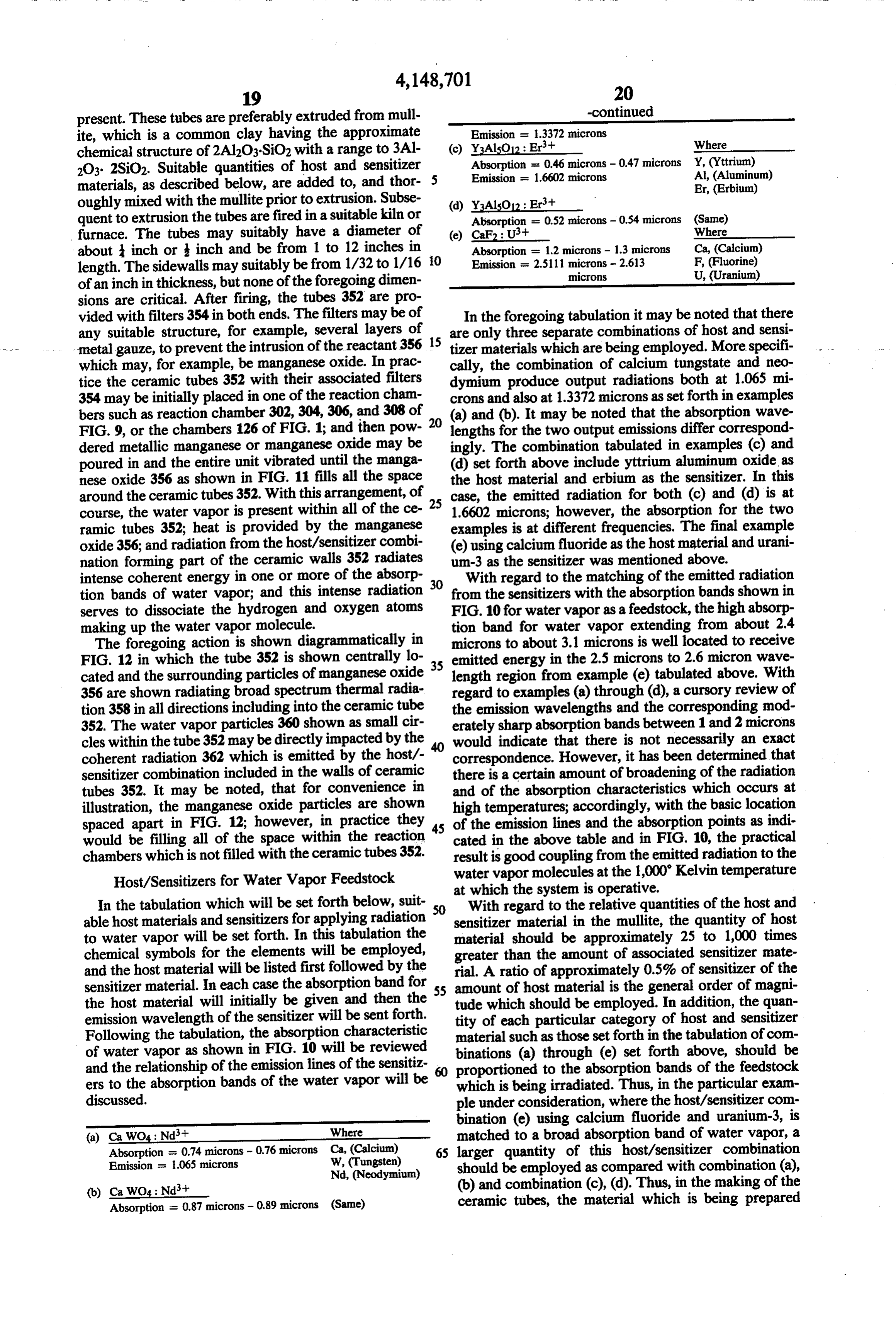
U, (Uranium) of an inch in thickness, but none of the foregoing dimen sions are critical. After firing, the tubes 352 are pro vided with filters 354 in both ends. The filters may be of In the foregoing tabulation it may be noted that there any suitable structure, for example, several layers of 15 are only three separate combinations of host and sensi metal gauze, to prevent the intrusion of the reactant 356 tizer materials which are being employed. More specifi which may, for example, be manganese oxide. In prac cally, the combination of calcium tungstate and neo tice the ceramic tubes 352 with their associated filters dymium produce output radiations both at 1.065 mi 354 may be initially placed in one of the reaction cham crons and also at 1.3372 microns as set forth in examples bers such as reaction chamber 302,304,306, and 308 of 20 (a) and (b). It may be noted that the absorption wave FIG. 9, or the chambers 126 of FIG. 1; and then pow lengths for the two output emissions differ correspond dered metallic manganese or manganese oxide may be ingly. The combination tabulated in examples (c) and poured in and the entire unit vibrated until the manga (d) set forth above include yttrium aluminum oxide as nese oxide 356 as shown in FIG. 11 fills all the space the host material and erbium as the sensitizer. In this around the ceramic tubes 352. With this arrangement, of 25 case, the emitted radiation for both (c) and (d) is at course, the water vapor is present within all of the ce 1.6602 microns; however, the absorption for the two ramic tubes 352; heat is provided by the manganese examples is at different frequencies. The final example oxide 356; and radiation from the host/sensitizer combi (e) using calcium fluoride as the host material and urani nation forming part of the ceramic walls 352 radiates um-3 as the sensitizer was mentioned above. intense coherent energy in one or more of the absorp With regard to the matching of the emitted radiation tion bands of water vapor; and this intense radiation 30 from the sensitizers with the absorption bands shown in serves to dissociate the hydrogen and oxygen atoms FIG. 10 for water vapor as a feedstock, the high absorp making up the water vapor molecule. tion band for water vapor extending from about 2.4 The foregoing action is shown diagrammatically in microns to about 3.1 microns is well located to receive FIG. 12 in which the tube 352 is shown centrally lo emitted energy in the 2.5 microns to 2.6 micron wave cated and the surrounding particles of manganese oxide 35 length region from example (e) tabulated above. With 356 are shown radiating broad spectrum thermal radia regard to examples (a) through (d), a cursory review of tion 358 in all directions including into the ceramic tube the emission wavelengths and the corresponding mod 352. The water vapor particles 360 shown as small cir erately sharp absorption bands between 1 and 2 microns cles within the tube 352 may be directly impacted by the would indicate that there is not necessarily an exact coherent radiation 362 which is emitted by the host/- correspondence. However, it has been determined that sensitizer combination included in the walls of ceramic there is a certain amount of broadening of the radiation tubes 352. It may be noted, that for convenience in and of the absorption characteristics which occurs at illustration, the manganese oxide particles are shown high temperatures; accordingly, with the basic location spaced apart in FIG. 12; however, in practice they 45 of the emission lines and the absorption points as indi would be filling all of the space within the reaction cated in the above table and in FIG. 10, the practical chambers which is not filled with the ceramic tubes 352. result is good coupling from the emitted radiation to the Host/Sensitizers for Water Vapor Feedstock water vapor molecules at the 1,000 Kelvin temperature at which the system is operative.
In the tabulation which will be set forth below, suit With regard to the relative quantities of the host and able host materials and sensitizers for applying radiation sensitizer material in the mullite, the quantity of host to water vapor will be set forth. In this tabulation the material should be approximately 25 to 1,000 times chemical symbols for the elements will be employed, greater than the amount of associated sensitizer mate and the host material will be listed first followed by the rial. A ratio of approximately 0.5% of sensitizer of the sensitizer material. In each case the absorption band for 55 amount of host material is the general order of magni the host material will initially be given and then the tude which should be employed. In addition, the quan emission wavelength of the sensitizer will be sent forth. tity of each particular category of host and sensitizer Following the tabulation, the absorption characteristic material such as those set forth in the tabulation of com of water vapor as shown in FIG. 10 will be reviewed binations (a) through (e) set forth above, should be and the relationship of the emission lines of the sensitiz 60 proportioned to the absorption bands of the feedstock ers to the absorption bands of the water vapor will be which is being irradiated. Thus, in the particular exam discussed. ple under consideration, where the host/sensitizer com bination (e) using calcium fluoride and uranium-3, is (a) Ca WO4: Nd’t Where matched to a broad absorption band of water vapor, a Absorption = 0.74 microns - 0.76 microns Ca, (Calcium) 65 larger quantity of this host/sensitizer combination Emission = i.065 microns W, (Tungsten) should be employed as compared with combination (a), Nd, (Neodymium) (b) Ca WO4: Nd’t (b) and combination (c), (d). Thus, in the making of the Absorption = 0.87 microns - 0.89 microns (Same) ceramic tubes, the material which is being prepared
Page 28
might include approximately 88% by weight of mullite, photons corresponding in energy to the Haser transi 8% by weight of the host/sensitizer combination (e), tion. Where such absorption into a higher level or band and 2% by weight of each of host/sensitizer combina is possible, the photon/phonon flux in the particulate tions (a), (b) and (c), (d). Similarly, in the event that the cavity is reduced and the metastable level depleted. wire mesh is employed, the host sensitizer/sensitizer For best coherence the active ions should occupy combinations may be added in the same proportions to equivalent positions in the host structure, so that there stainless steel wire and the combination material drawn will not be a multiplicity of spectra. When these ions are into wires and formed into mesh. Alternatively, after im completely unique sites, the emission spectrum has the preparation of the stainless steel wire cells, mullite the minimum detail and line width consistent with the together with the host sensitizer combinations could be 10 site symmetry, the crystal field, and the active-ion con applied in several bands in the plastic state around the centration. In general, the higher the site symmetry the stainless steel wire mesh cells, and then fired, to pro more degenerate the electronic states of the active ion. duce the desired result. This result, as mentioned above, Therefore, fewer distinct transitions should be observed involves the provision of spaces throughout a body of in fluorescence and, on the average, each emission tran material constituting a heat reservoir, and locating 15 sition should flouresce a greater portion of the absorbed host/sensitizer combinations around the boundaries of energy. However, there are also fewer distinct absorp these spaces or voids in the material. tion transitions, and certain emission transitions may be The chemical formula for mullite was given above, favored in a low-symmetry environment. As long as the and it is again noted that mullite includes aluminum emission transitions are few in number, the low symme oxide Al2O3 and silicon dioxide SiO2 in certain propor 20 try environment may prove to be advantageous by tions noted above. In order to enhance the "HASER' virtue of a broader absorption coverage. action and increase the energization of the host/sensit Different classes of active ions seldom find optimum izer combinations (a) through (e) set forth above, a environments in the same host structure. Different acti material such as chromium, which acts as a sensitizer in vator ions are best accommodated in oxides or fluo cooperation with the aluminum oxide in mullite which 25 rides, where the cations of the matrix are approximately acts as the host material. The chromium-aluminum ox equal in size to the activator. Al2O3, MgO, MgF2, and ide, sensitizer-host combination produces strong output Zn,F2 are typical matrices for transitionmetal ions, CaF2 radiation at a number of wavelengths, including output is particularly useful for divalent rare-earth ions, and radiation centered at 0.6934 microns, when the Al2O3 is CaWO4, LaF3, and Y2O3 are best suited for trivalent absorbing energy at 0.5 microns. The radiation centered 30 rare-earth ions for lasers. Y3Al5O12 can readily accom at 0.6934 is broadened at the high operating conditions modate both trivalent rare-earth ions and trivalent 3d so that the radiation extends from 0.6 or 0.65 to 0.75 or transition-metal ions. Certain crystals have conve 0.8 microns, thus providing supplemental input energy niently disposed matrix absorption bands and these can to example (a) set forth hereinabove, which involves be used to absorb pumped radiation over a broad spec absorption at about 0.74 to 0.76 microns. The Al2O3/Cr 35 trum.
combination may also directly apply energy to the feed The excitation may be subsequently transferred to stock when the output radiation is of the proper fre trivalent rare-earth ions contained in the matrix and quency and may also pump other host/sensitizer combi therefore, greatly enhance the overall efficiency of nations. When chromium is used it will be present in fluorescence. It probably is essential to move into the quantities in the order of five percent by weight or less visible region, to obtain continuous operation for mo of the mullite employed as the basic material of the lybdates or niobates.
tubes 352 as shown in FIGS. 11 and 12. In comparison, materials which have their matrix absorption edges well above the excitation range but
Material Requirements absorb strongly as a result of the active ions having The primary requirements for potential solid-state 45 strong absorption bands of their own, together with Maser/Haser materials are, first, that the composition narrow emission lines, can afford very favorable pump should fluoresce with a suitably high intensity at ele ing conditions. w vated temperatures by means of thermal energy alone Ions such as, Cr, Chromium, and, Dy2+, Dyspro and, second, that the matrix should be transparent or sium offer this advantage.
has no absorption transition at the operation frequency; 50 The past decade has provided rapid extension of it should also be chemically stable and have no caustic spectral measurements and theoretical analysis, such characteristic. that the properties of most of the divalent and trivalent Preferably, the terminal level of the Haser transition activator species are well understood. The interest in of the active ion should be far enough above the ground solid-state masers and lasers, has motivated the prepara state so that three of four-level operation is possible and 55 tion of various crystals containing divalent rare-earth at elevated temperatures. ion species and the extensive study of their infrared The lifetime of the metastable level from which the characteristics. Parallel studies of the infrared proper Haser transition originates should be, insofar as possible, ties of the transition-metal ions and trivalent rare-earth equal to the lifetime for spontaneous emission with no 60 ions have been equally productive. constraints imposed by competitive dissipation to the The selection of materials for Hasers which will oper matrix. In four-level operation the lifetime of the termi ate in the infrared region depends on the disposition of nal level of the transition must be smaller than that of the vibrational bands in the matrices. Because vibra the metastable level; otherwise, a suitable excess popu tional levels may drain an electronic state, they should lation in the upper level cannot be maintained. not be too close below the metastable level, or the latter This condition is generally obtained when the termi 65 should lie below the vibrational levels in energy. nal level lies in the phonon absorption region, prefera Suitable coupled pairs which provide a mutual cross bly between 6000 and 19,000 cm. In addition, it is relacation can also be used advantageously to minimize helpful for the excited active ion to be unable to absorb loss of efficiency due to fluorescence from levels lying
Page 29
higher than the metastable level of interest and loss to study of controlled luminescence of solids provide in the phonon spectrum. It is also desirable to increase the formation on band structures and energy levels of impu efficiencies of masers that terminate on phonon levels. rities and imperfections, In some cases, the spectra of This mechanism of operation offers the possibility of a impurities yield, through the application of crystal field maser that can be tuned over a broad range of frequen 5 theory, information on the symmetry and strength of CS, the crystal field at the impurity site. The absorption or Preferred Lattices excitation spectra involve electronic states of the system with equilibrium nuclear coordinates characteristic of
Oxygen-dominated compounds are those in which the ground state; luminescent emission spectra involves oxygen is a major chemical constituent of the host lat 10 electronic states with the equilibrium nuclear coordi tice. They may be classified according to their chemical nates of the emitting state.
composition into four groups. Additionally, detailed theoretical knowledge of band The first group, comprising the simplest compounds, structure and of impurities and imperfections obtained has the generic formula M.O., representative numbers from semiconductor and photoconductor research pro being the alkaline earth oxides and Al2O3, Y2O3, and 15 vides understanding of the luminescence of these mate ThO2, with Cr3+, Mn2+, and the rare earths as com rials.
mon activators. Other compounds included in the ge Luminescence is generally investigated as a steady neric formula are CuO, and ZnS and the other II-VI state phenomenon, wherein the compound interacts wide-band-gap compounds, with the excitation source and emits radiated energy The second and largest group are the binary oxides, 20 continuously. The thermodynamic parameters of the MAO, where M is any element of Group II, A or B, compound remain time independent at every point in and Period 2 to 6, and A is Ti, Zr, V, Nb, Mo, B, Al, Si, the system, despite the occurrence of excitation, emis Ge, P, As, Sb, or S. sion, and dissipative processes. In many cases x = 4y, the oxygens nearly tetrahe Irreversible thermodynamics is concerned with just drally arranged around the multivalent atom, A. 25 such open systems, which interact with their environ The common activators are Mn, Mn+, Agt, ment in a stationary way.
Sn2+, Th, Pb2+, and the rare earths. Included in this group also are the well-known self-activated com theItentropy is a principle of irreversible thermodynamics that pounds comprised of tungstates and molybdates, which region of theproduction is positive in every macroscopic are commonly called scheelites (although some do not 30 Macroscopic regions refer to irreversible system undergoing regions processes.
large enough have the scheelite structure). These require no activat for microscopic fluctuations to exist but small enough ing impurity, because the energy transitions take place for approximate equilibrium to exist within each region. within the anion, although impurity-activated lumines We are especially interested in the more complex exci cence is also observed. tation mechanisms involving energy transfer between Of the impurity-activated members of the binary 35 different macroscopic regions not in equilibrium with oxides, the borates, phosphates and silicates are the each other.
most numerous.
Ternary systems, MABO, constitute the third Light Absorption and Color category. M and A and B are the elements listed in the An electromatic radiation, (such as radiowave, light, binary systems plus the alkali metals. and X-ray) can be characterized by its particular wave The most common activators, other than the rare length, LAMBDA, M (measured in cm or A), or by its earths, are those listed with the binary oxides. There are wave number, NU, v (the reciprocal of the wave a few ternary compounds not containing tungsten or length), v = ava, commonly expressed in reciprocal molybdenum which are believed to be self-activated. centimeters, cm-l.
There are many other oxygen-containing inorganic 45 Each unit of radiation (a photon) corresponds to a luminescent solids, including a large number of rare quantum earth salts and impurity-activated nitrites, carbonates, tional to of radiant energy, E, which is directly propor etc. The work on the latter is largely incomplete. The tions are the wave number, V. Since chemical calcula founded on a mole basis, in discussing the work on the rare-earth salts constitutes a well-studied separate discipline (Diecke et al., 1961). 50 relationship between radiant energy and chemical pro Considering the small number of possible combina cesses (responsive activators and hosts) it is convenient tions of simple oxides and activators, it is surprising that can do so radiant to express with energy in kcal/mole of photons. We this accepted relationship: the radiant new prospects in this group continue to be found. New compounds, however, consisting of oxides of antimony, energy in 1 mole of photons, with v = 350 cm-1, is germanium, thorium, calcium, strontium, yttrium, and 55 equal to 1 kcal.
gadolinium with various activators have been devel kcal/mole) Therefore, we can obtain the energy (expressed in oped over the last few years. for photons of a given wave number simply The valence of manganese in phosphors or com by multiplying the value of v expressed in cm-1 by the pounds is interesting because of its use as an activator in conversion factor many lattices. Kroger (1948) showed that the broad kcal/mole of photons structureless red or green emission spectra of man 350 cm ganese-activated compounds is generally due to Mn2+, whereas the red narrow-banded emission is due to For example, the energy of light photons with v = Mn4+. 20,000 cm 1 is:
SUMMARY
energy = 20,000 x kcal/mole of photons
In the same way that the spectroscopy of atoms pro vided basic information on atomic structure, careful 57. Kcal/mole of photons
Page 30
-continued (2.2) Internal energy of a phonon gas.
and the energy of a single photon of v = 20,000 cm is: (2.3) Einstein and Debye approximations of the den energy 1 photon = 57.1 kcal/mole of ph.
6.02 x 10 photons/mole of ph. sity of (A) phonon states.
9.48 x 10². Kcal/photon. 5 (2.4) CeS. Phonons and photons; similarities and differ
The wave number, and the energy, of electromag (3.)ofIon-Photon. Radiation
Interaction: Absorption and Emission netic radiations varies within an extremely wide range - v = 1014 cm-1 for the y-rays emitted in nuclear (3.1) ion-radiation interaction. reactions to v = 10-6cm for radiowaves. In between (3.2) Expansion of the interaction hamiltonian. Dif these two extremes, there is a continuum of radiations of 10 ferent types of radiation. intermediate wave numbers - the "visible region', (3.3) Density of final states which extends approximately from 27,000 cm to (3.4) Transition probability per unit time. 13,500 cm-1. (3.5) Dipole radiation. In general, when white light strikes a substance, part 15 (3.6) Selection rules for radiative transistion of the light is absorbed and part is transmitted (if the (3.7) Selection rules for transitions between eigen substance is transparent) or part is reflected (if the sub states of angular momentum, stance is opaque). A substance may absorb preferen (3.8) Selection rules for atomic systems. tially the light photons of one (or more) region(s) of the (3.9) Electric dipole radiation. spectrum, so that the transmitted light or the reflected 20 (3.11) (3.10) Magnetic dipole radiation. light is relatively richer in the radiations of the remain Electric quadrupole radiation. ing regions. (3.12) Selection rules for ions in crystals. The combined effect of these remaining radiations is (3.13) Intensities of radiative transitions observed as a particular color (when it is in the visible (4.)Thermal Ion-Vibration Interaction: Radiationless Processes, Shift, and Broadening of Sharp Spectral spectrum). Lines
For example, a substance that, when exposed to white 25 (4.1) Ion-vibration interaction. light, absorbs almost all photons in the entire yellow - to (4.2) Radiationless processes in a crystal-absorption - violet region (say from 17,000 to 27,000 cm) will and emission of a phonon. "appear red', because only the radiations in the red (4.3) Raman processes. region of the spectrum (13,500 to about 17,000 cm), 30 (4.4) Orbach processes. which are not absorbed, remain to be observed. (4.5) Multiphonon processes. Similarly, a substance that "appears yellow' absorbs (4.6) Line broadening mechanisms photons of both the green-to-violet region (from 19,000 (4.7) Probability densities and superposition of proba cm-1 to 27,000 cm-1) and the red region (from 13,500 bility densities: Voigt profile. to 16,000 cm) of the visible spectrum. 35 (4.8) Thermal broadening of sharp lines. Since light (radiation) is energy, the absorption of radiation is absorption of energy; it is well known, that, (5.)(4.9) Raman scattering of phonons Vibrational-Electronic Interaction if a substance absorbs light, the corresponding absorbed (5.1) Ion-vibration interaction in molecular com energy may be used to promote certain atoms, ions, or plexes.
molecules of a substance from "ground-state' to an (5.2) Vibronic spectra of molecular complexes, "excited state'. For example, an atom, ion, or molecule (5.3) Vibronic lines in absorption. which absorbs a photon of a given wave number takes (5.4) Selection rules for vibronic processes. on a 'quantun' of energy that may serve to promote one (5.5) Space groups and lattice vibrations. electron from a lower energy orbital to a higher (avail (5.6) Normal modes of vibrations in crystals. able) energy orbital. In general, different electronic 45 (5.7) Lattice absorption in perfect crystals, transitions involve the absorption of different quanta of (5.8) Phonon activation due to impurity ions in crys energy. Haser Design Considerations tals. w Some of the factors which are involved in the design (5.9) Selection rules for vibronic transitions due to of Haser apparatus include the following: magnetic impurities in crystals. (a) Thermally isolated chamber. 50 (b) Sensitizers-activators responsive to input heat Specific Examples energy frequencies.
(c) Design amounts of "impurity' sensitizers re ofSome Haser underlying principles involved in the selection systems have been set out hereinabove and a quired. preferred embodiment has been described which in (d) Design the host solid while considering the fol 55 volves water vapor as a feedstock and the generation of lowing: hydrogen and/or hydrogen peroxide. It is to be under (1) Lattice Vibrations stood that the Haser concept is not limited to the spe (i.1) Geometry of crystalline solids. ( cific embodiment described herein but has more general (1.2) Crystal lattice and reciprocal lattice. applicability in the conversion of broad spectrum heat (1.3) Brillouin zone and g-space. 60 energy or radiation to particular frequencies which lie (1.4) Lattice vibrations of an infinite crystal with one within the absorption band or bands of any selected atom per unit cell. feedstock.
(1.5) Lattice vibrations of a finite crystal with one The feedstock may be gaseous or liquid or even a atom per unit cell. slurry, and may be brought into proximity with the heat (1.6) Lattice vibrations of a crystal with more than reservoir and associated host and sensitizer material in one atom per unit cell. any desired and practical manner. The heat in the heat (2) Thermodynamics of Phonons reservoir may be generated in any suitable manner in (2.1) Density matrix of an ensemble cluding the use of the exothermic reactor for generating
Page 31
27 -continued hydrogen and hydrogen peroxide and/or the combus tion of the hydrogen and hydrogen peroxide. Emission = 1.01 microns The feedstock may for example be directed through the heat reservoir by a pipe suitable coiled to provide for adequate exposure to the radiation. The pipe may be 5 Example No. 6 transparent to the radiation being applied to the feed stock; or alternatively, the pipe may be made of material containing the specially selected host and sensitizer B2H, PhNO2-B2OH, Several Nitrogen Compounds=(Reaction)
material. Absorption = 0.5 micron In the following examples, a number of reactions are 10 Emission = 1.0612 microns set forth and these are followed by an identification of a host and sensitizer material which will concentrate the broader spectrum heat energy to one of the absorption Example No. 7 bands of the feedstock. Incidentally, in the following 15 examples, in addition to the standard symbols for the Me2CO, Et2O (solution)- 150 - Propyl Alcohol, elements, the following abbreviations are used: Et for Additional Compounds=(Reaction) ethyl, C2H5; Ph for phenyl, C6H5; Pr for propyl, C3H7; Ca WO: WUAE. Nd
and Bu for butyl, C4H9. In addition to the host and Absorption = 0.57 - 0.60 micron sensitizers shown in each of the following examples, 20 Emission = 0.9145 micron
Al2O3 in mullite and Cr +3 may advantageously be used (absorption at 0.5 microns; emission centered at 0.6934 microns). As noted above, the mullite may con Example No. 8 veniently be employed to physically support the host and sensitizer materials. The actual examples follow: 25 Cyclohexanone - Caproic Acid, Resin, Aldehyde = (Reaction)
Absorption = 0.39 - 0.46 micron
Emission = 1.16 microns
B2H, Et2O (solution) -->
Hydrobenzoin, Isohydrobenzoin = (Reaction) 30
Al2O3 (millite): Crit + Sr F2: Sm't Example No. 9 Absorption = 0.5 microns Absorption = 0.58 - 0.68 micron
micron Carvone, EtOH (aq)-> Ketone Resembling Camphor,
Example No. 2 Absorption = 0.43 - 0.49 micron
Emission = 1.0468 microns
AcH, NHHCN(aq) - C6H12O3N2 = (Reaction)
LaF3: Pr’t Example No. 10 Absorption = 0.43 - 0.48 micron
Emission = 0.5985 micron
Camphor, EtOH (aq) -> Campholenic Acid, = (Reaction)
Emission = 0.6967 micron
PARALDEHYDE, O2- H2O2 = (Reaction) 2.36 microns CaF2: Smt
Absorption = 0.4 - 0.45 micron
Emission = 0.7085 micron Example No. 11 Example No. 4 Coumarin, EtOH, Paraldehyde, -- Hydro - D - Counaria or C6H6 (solution) = (Reaction)
CaWO:E. Ndh
HCHO, FeCls (aq) - FeCl2.HCO2H, HCL = (Reaction) 55 Absorption = 0.57- 0.6074 - 0.76 (glycolaldehyde) 0.44 - 0.46 micron Y2O3: Eut Emission = 0.9145 micron 1.065 microns
Absorption = 0.2 - 0.28 micron 2.046 microns Emission = 0.6113 micron
Example No. 5 Example No. 12 B2H, Aromatic Ketones - Polymers, other Ketones, =(Reaction) 65 Benzoin, EtOH (solution) -> Hydrobenzoin, Ach3, Isoform Benzoates Resin = (Reaction)
Y3Al5O12: Yb't Absorption = 0.87 micron Absorption = 0.9 - 1.0 microns
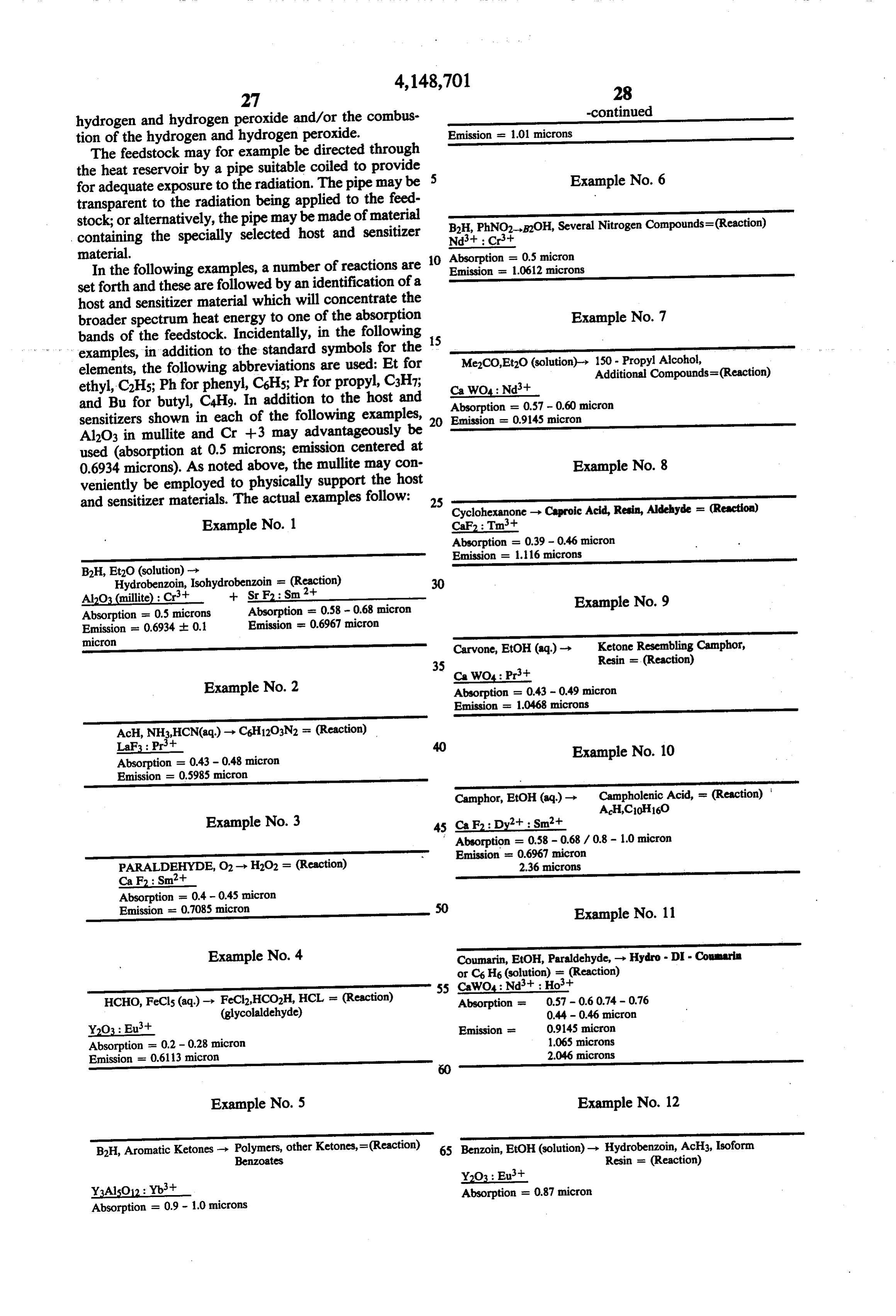
Page 32
-continued line 438 via valve 440. The additional oxygen promotes Emission - 0.613 micron the formation of hydrogen peroxide, which is, with the hydrogen, drawn off through line 434.
The overall cycle of reaction chamber 402 may be
Example No. 13 5 substantially as indicated by one of the two plots shown in FIG. 7. Accordingly with the steam valve 432 and the valve 436 to the hydrogen storage tank both closed,
Quinone, Et2O (solution) -> Hydroquinone, Resins = (Reaction) the vacuum may be applied to the reaction chamber 402 Same Host/Sensitizer; Absorption; and Emission as so that disproportionation of the oxygen from the reac Nos. 1, 3 and 4 10 tant takes place.
While the hydrogen displacement at high pressure
Example No. 14 and the oxygen disproportionation phase of the cycle at low pressure is occurring in the main reaction chamber 402, the feed stock may be continuously passed through
Thymoquinone, Et2O (solution) - Polymer (Polythymoquinone) 15 the heat and radiation exchanger 414, 416, 418, at a = (Reaction suitable rate to maintain the desired high temperature Same Host/Sensitizer; Absorption; and Emission as
Nos. 1 and 3 and high level of radiation of the feedstock. Incidentally the tubes 418 interconnecting the upper chamber 414 and the lower chamber 416 may be made of mullite
Example No. 15 20 including the host/sensitizer materials mentioned in the various examples given above. Similarly the manifolds 4 - Me Quinoline - Resin, Alkali Soluble Product = (Reaction 414 and 416 may be made of such materials. Alterna
Same Host/Sensitizer; Absorption; and Emission as tively the elements 414, 416, and 418, may be made of Nos. 5, 6, and 8 25 metal, such as stainless steel, to which suitable quantities of host/sensitizer materials have been added in order to
FIG. 13 is a schematic showing of an apparatus for a givethethefeed desired intimate irradiation action with regard continuously processing feedstock such as the materials to Instead stock.
disclosed in the foregoing examples, or steam, of course. in FIG. 13, ausing of a single reaction chamber as shown heat and irradiation exchange unit could
In FIG. 13 the reaction chamber 402 is provided with 30 be employed with a multiple reaction chamber appara upper and lower manifold chambers 404 and 406 which tus such as that shown in FIG. 9. When used with a are separated from the main portion of the reaction multiple reaction chamber arrangement such as that chamber 402 by apertured plates 408 and 410. Within the reaction chamber 402 are a large number of the shown in FIG. 9, of course the heat exchange elements ceramic tubes 412 such as those shown in FIG. 11. All 35 must make sealing engagement with the walls of the of the space within chamber 402 apart from that occu pressures individual reaction chambers which will be at different pied by the tubes 354 is filled with a reactant such as during different portions of the individual manganese oxide or other reactants disclosed elsewhere staggered cycles in the different reaction chambers. in the present case and in my prior co-pending specifica It may be noted that, in accordance with disclosures tion cited above, in my prior co-pending patent application cited above, A heat or radiation exchanger including upper and and teachings found elsewhere in the present specifica lower manifold structures 414 and 416 as well as the tion, the hydrogen and H2O2 "tailings', obtained as a interconnecting tubes or pipes 418 exposes the feed vacuum is being drawn on line 438, and such output stock, which is applied through input tube 420 and hydrogen and/or hydrogen peroxide from line 434 as brought out through tube 422, to the high temperatures 45 may be desired, may be applied through line 426 to the and radiation present within the main reaction chamber central burner 424. This may serve the purpose of sup 402. plying additional heat to the entire unit to permit more At the center of the apparatus shown in FIG. 13 is a rapid flow offeed stock through lines 420 and 422 with burner 424 to which a lower inlet pipe 426 and an upper out loss of temperature in reaction chamber 402. outlet pipe 428 are connected. This central burner unit 50 Energy Balance may be of the type shown in FIG. 9 of the drawings and as described hereinabove. The entire reaction chamber In my prior co-pending patent application an "En 402 shown in FIG. 13 is fully insulated and mounted as ergy Balance' section was included. In the present shown in FIG. 9, and equipped with suitable automatic specification, a portion of the prior analysis will be set valving of the type described above in connection with 55 forth, and a more thorough energy analysis involving other embodiments of the invention. the new material in this application will be included. In operation, steam is initially supplied to the reaction In view of the fact that the apparatus of the present chamber 402 through inlet line 430 when valve 432 is type and as disclosed in my prior application are exo opened. Of course prior to this initial step, the reaction thermic on a net basis and also produces hydrogen or chamber 402 has been preheated to a temperature in the hydrogen peroxide which can be burned, there have order of 1000' Kelvin, and the steam is supplied under been some suggestions that certain socalled Laws of high pressure. Hydrogen is then displaced by the action Thermodynamics are being violated. This is of course of the reactant, and the host/sensitizer materials in not the case, as will be developed by the Energy Bal cluded in tubes 412, as described above. Hydrogen H2 ance analysis set forth below.
and hydrogen peroxide H2O2 are drawn off through the 6s From an overall standpoint, the present system may upper manifold 404 and the connecting line 434 through be viewed as providing an energy balance and not vio value 436. During the hydrogen displacement phase of lating any "Laws of Thermodynamics' as a result of the the cycle, additional oxygen may be supplied through low energy content gaseous products which are re
Page 33
leased in the course of the process. These low energy Now, from a Gibbs Free Energy (G) Analysis stand gaseous products may include HO and HO2, which are point involving Enthalpy (Heat, H), Entropy (S), and less well known gaseous products. When these gaseous temperature T, the following analysis obtains: products are released into the atmosphere, it is believed In the following analyses, the enthalpies and entro that they absorb high frequency radiations, and eventu pies of the starting reactants are subtracted from the ally change state to become hydrogen gas, oxygen gas, enthalpies and entropies, respectively, associated with water vapor, atomic hydrogen and atomic oxygen. In the products. The letters "in' have been associated with one sense, therefore, the present system may be consid the initial values relating to the starting products. ered to utilize solar energy.
The stoichiometric reactions set forth below repre 10 Oxygen Sequestering Reaction sent one of several modes of operation which may ob (Upper Equation designated "Stoichiometric Reaction") tain in implementations of the present invention. AHam: 20-706) (in)2(-228.6) (in)4(-126.7) -432 The foregoing equations may be analyzed from two - 43.2-33.96 different standpoints. Incidentally, it may be noted that Som: 20+45.11) (in)2(+264) (in)4(+12.7)--43.89
the "2HO' designated (4) in the upper equation is actu 15 AH"eac: -627.16-(-598,4) = -28.76 Kcal/Mol-Eqn ally evolved in the disproportionation phase. In addi AS'react. --194.59-(+143.02)= +51.57 Cal/Mol-Eqn X Deg. tion, a portion of the hydrogen gas H2 from (6) in the 1000 X (--S1.5 upper equation is an input in the lower equation which TAs: AG:AH-TAS
Stilfit
combines with the disproportionated oxygen to form AG: = -80.33 Kcal/Mol-Eqn
HO. Also, of course, the incident photons are applied in Reverse Reaction
the atmosphere, and not in the apparatus per se. It AH/orm: 4(-126.7) (in) 20-228.6) -43.2 should also be noted that the O2 input designated (2) is Son: 4(+12.7) (in) 20--264) +43.89 essentially optional and may involve the venturi unit AS'react;
STOICHIOMETRIC REACTION (ONE OF SEVERAL MODES)
E - 237.143 KCALMMOLE OF
(1) CATALYST to Y 2 H2O0 -S2Mn2O3 -> MnO2() + H20+ g; O. O. 'H-G-2HO -GH2O2(g) -Go (OR)
REVERSE REACTION
or inlet 217, of FIG. 6, whereby additional O2 is sup AG : AH - TAS = + 6.40 - (+45.89)
plied to generate H2O2, as noted above. Complete Cycle
Now, the upper equation will be analyzed from a 50 GB)= -28.76 + (+6.40) = -22.36 Kcal/Mol-Eqn potential energy standpoint:
POTENTIAL ENERGYN:
(1) 2 H2O 1412 From the foregoing analysis, it may be noted that the (2) O2 + H2 43.2 ) = 421.543 K.Cal. 55 heat or enthalpy for the hydrogen generation portion of (3) hy 237,143 the cycle is equal to -28.76 K Cal/Mol-Eqn, which
POTENTIAL ENERGY OUT:
means that the reaction is exothermic. For the "Reverse
K.Cal Reaction' or the oxygen disproportionation part of the (4) 2HO 43.2 cycle, the heat or enthalpy figure is +6.40 K. Cal/Mol (5) H--O--O--H 223.96 Eqn. This means that the disproportionation part of the
cycle is endothermic, but that the heat required is much (7) H2O2 114,262 381,422 K.Cal (H2O2Out) less than that generated in the other portion of the cy cle. With thoroughly insulated equipment the heat gen erated during the exothermic portion of the cycle, in the
Efficiency (H2 Out) = 0.78 65 same or other adjacent reaction chambers, is more than Efficiency (H2O2 Out) = 0.90 sufficient to provide the heat needed during the dispro Actually, there is often a combination of H2 and portionation part of the cycle. It may also be noted that H2O2 resulting in an intermediate efficiency. the positive entropy value for the "Reverse Reaction',
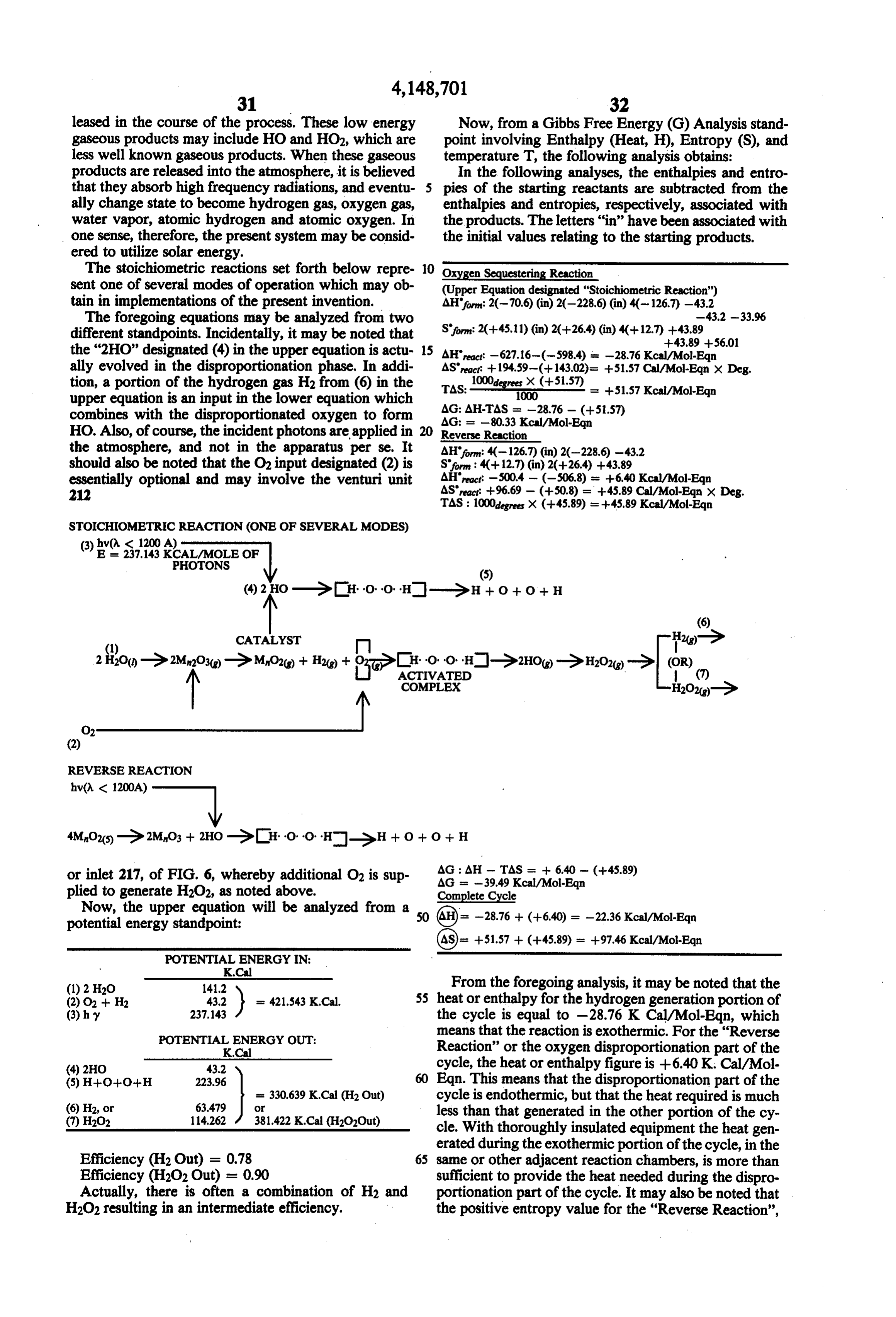
Page 34
or the disproportionation cycle, indicates that this reac tional Bureau of Standards Accession No. 6500390, tion will go forward spontaneously. N.B.S. Circular No. 500, dated Feb. 1952, pages 122 Energy Balance - Second Mode (MnO2) and 123 (Mn2O3)
Another pair of (1) Displacement of Hydrogen and . . Thermodynamic Properties of the Elements Published (2) Disproportionation reactions appears below, to November 1956, American Chemical Society, 1155 gether with a classical Gibbs Free Energy, Analysis. Sixteenth Street, N.W., Washington 6, D.C. Also included are the text citations for the entropy and 4. H2 Enthalpy (H) 1000 K. = 0 (By Definition) enthalpy values used in the analysis. The following 5. O2 Enthalpy (H) 1000 K. = 0 (By Definition) mode emphasizes the production of hydrogen peroxide, 10 6. O2 Entropy (S) 1000 K. = 49.0 H2O2, and carries over its use in the disproportionation 7. H2O Enthalpy (H) 1000 K. = 59.24 part of the cycle. It may also be noted that the first H2O Entropy (S) 1000 K. = 55.59 mode and second mode presentations are not precisely "Thermodynamic Properties of Minerals and Related comparable as H2O(e) is assumed as an input for the first Substances . . .” - Geological Survey Bulletin 1259 mode, and H2O(g) is assumed as an input for the second 15 Washington, D.C., U.S. Dept. of the Interior, 1968, p. mode as set forth below. As indicated by the negative 114.
value of the enthalpy for the two reactions of the sec 8. OH Enthalpy (H) 1000 K. = 9.13 ond mode, it is also exothermic on an overall basis. 9. H2O2. Enthalpy (H) 1000 K. = 33.46 The equations for (1) hydrogen displacement and (2) 10, OH Entropy (S) 1000 K. = 52.49 oxygen disproportionation, are set forth below, to- 20 11. H2O2 Entropy (S) 1000 K. =70.94 gether with their associated Enthalpy (H), Entropy (S) 12. H2O Entropy (S) 1000 K = 55.59 and Gibbs Free Energy functions. TRCTables, Selected Values of Properties of Chemical
DISPLACING HYDROGEN
AHS2: 2C-59.24) 20-228.39) 4(-123.63) 0 0 20-33.96) S9: 2C--55.59) 20+40,13) 4(+19.46) 2(+39.70) 2(+49.00) 2(+7094)
Oxygen
Disproportionation
exit machine
AHFo:4(123.63) 20-228.39) -59.2400
ASRec: +233.98 - (+77.84) = + 156.14 Cal/Mol-Eqn. x Degrees
TAs: -a -- = +156.14 Kcal/Mol/Eqn.
The values for Enthalpy (H) and Entrophy (S) used 60 in the foregoing analyses are all taken from published texts as follows: Compounds, Thermodynamics Research Center, Texas 1. MnO2 Enthalpy (H) 900 K. = 123.63 A&M University; Table 2 IT for items 9-12 above; Entropy (S) 900 K. = 19.46 Table 2 IW for items 7 and 8 above. 2. Mn2O3 Enthalpy (H) 1000 K. = -228.39 65 From the negative value of -8Kcal/Mol-Eqn. of the Entropy (S) 1000 K. = 40.13 enthalpy (heat) of the entire reaction, including both Selected values of Chemical Thermodynamic Proper diplacing hydrogen from water vapor and dispropor ties, by F. D. Rossini et al, and U.S. Government Na tionating oxygen from the reactant, it is clear that the
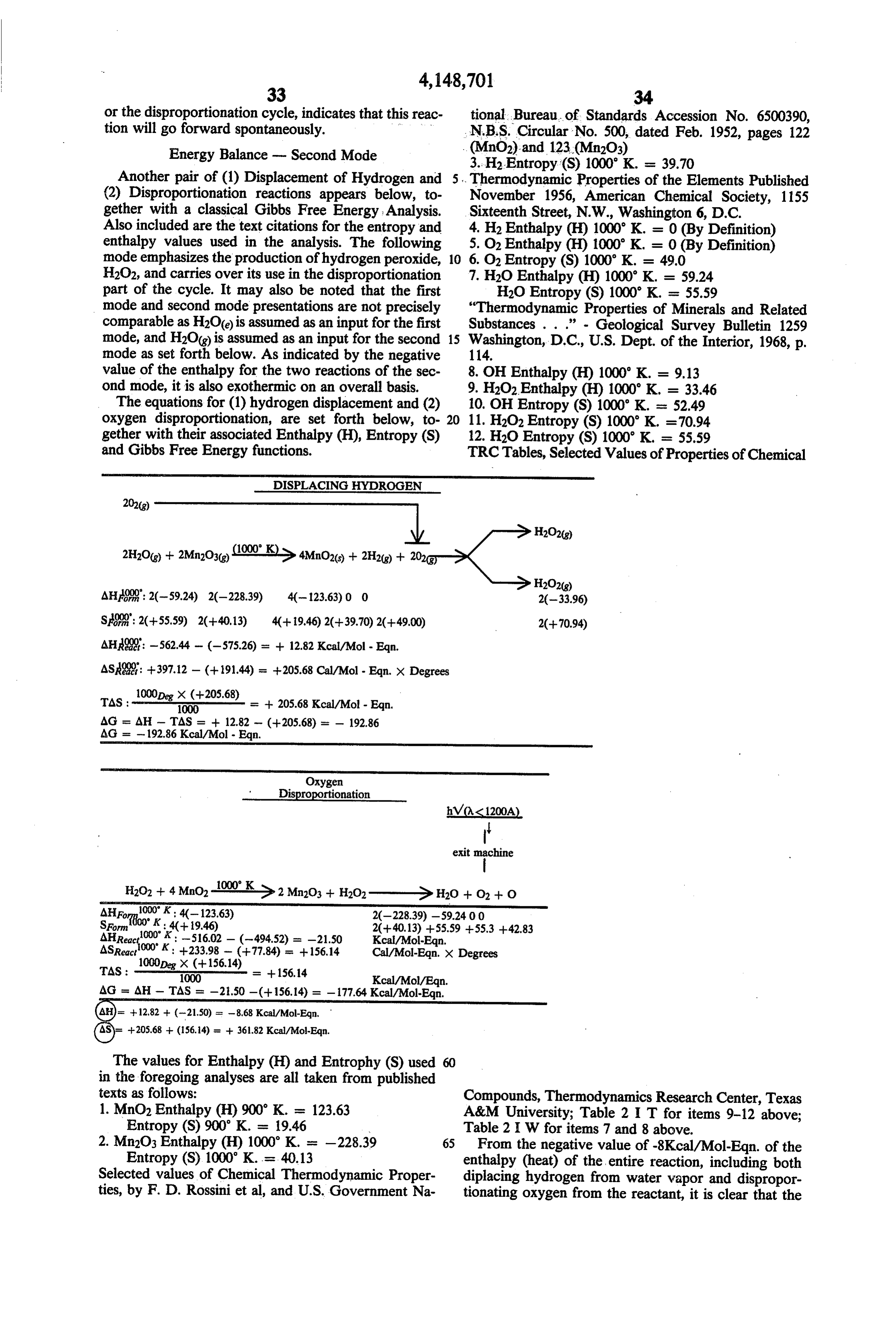
Page 35
process is exothermic, in addition to generating hydro -continued gen and/or hydrogen peroxide. And this surprising RETURNED TO NATURE result, in one or the other or a combination of the modes A. Potential Energy described in the foregoing equations has been con B. Combuston of 5.22 cu. ft. H2O2 x 38 BTU/cu. ft. firmed by the operation of prototypes using manganese 5 - 1660.00 BTU = 418.5 Kilocalories .
oxide as the reactant,
Set forth below is a further analysis involving the Required Energy (from J) 418.5 Kcal - Energy from Combustion, 418.5 Kcal as 0 photon dissociation of H2O, and an examination of the energy "borrowed from nature' and "returned to na 10 In closing, reference is again made to my copending ture', or to the environment. In connection with the following analyses, it may be noted that the energy for patent application Ser. No. 768,808, filed Feb. 15, 1977, photon dissociation of the H2O is obtained from the in which more detail is presented relative to the temper heat reservoir of hot reactant which is of course main atures, pressures, and other reactants which may be tained at an elevated temperature by the net exothermic used. As noted in the prior specification, the tempera nature of the hydrogen displacement and oxygen dis 15 ture of operation should be above the dissociation tem perature for oxygen for the reactant being employed at proportionation cycle. When mention is made of the atmospheric pressure. Advantageous high speed results combustion of H2O2 in the following analysis, this com have been achieved with the reactant in the pyroplastic bustion is in the course of performing useful work such state of incipient fusion Concerning pressures, the pres as driving an engine, or the like, apart from the reaction chamber as described herein. 20 sure during dissociation should be at least as low as
PHOTON DISSOCATION OF H2O)
A. Average number of <0.008)) particulates in 539.0 Cu. in reaction chamber is
Assuming radiated energy frequency averages
Assuming a continuum of 15 seconds
Since there are 6.02 x 10 photons in 1 mole (of photons)
Energy (15 sec.) = 10.256632 moles photons
E. Converting to Kilocalories
Energy = Kilocalories
F. Energy Required to Dissociate (1) Mole H2O
G. (1) Dissociation by Reactant 200 Moles H2O) (2) Dissociation by Radiant Energy 4.58 Moles H2O)
Total 6.58 Moles H2O)
J. Energy Required to Operate Unit for 15.0 Seconds (1) Dissociating 6.58 Moles Liquid Water at 70.6 Kcal/Mole = 389.8 (2) Sensible Heat Lost in Gases and Cooling Water s: 22.4 (3) Radiated Heat Losses (all surfaces) a 5.29 (4) Vacuum Pump (1.0 H.P.) as 0.27 (5) Water Pressure Pump (1.0 H.P.) is 0.27 (6) Cooling Fan (Electronic Controls) (0.3 H.P.) = 0.10 (7) Cam-Motor and DC Controls (0.3 H.P.) is 0.10 (8) Digital Readouts Power (0.1 H.P.) is 0.03 (9) Compressed Air (0.5 H.P.) is 0.14 (10) Compressed Hydrogen (0.5 H.P.) = 0.14
K. Energy Balance = Output Minus Input
atmospheric pressure, and preferably a vacuum should
BORROWED FROM NATURE be applied to reduce the pressure to a fraction of atmo (during 15.0 sec. period) spheric. The vacuum may be applied to draw the tail A. Energy Kcal 65 ings through the burner to extract additional heat from 1. 6.58 Moles H2O(1) x 70.6 Kcal/Mol = 389.8 the tailings. During the hydrogen displacement portion 2. Peripheral Equipment (15.0 sec.) 28.69 of the cycle the pressure should be well above atmo (Kcal) TOTAL = 418.5 spheric to facilitate sequestering of the oxygen by the
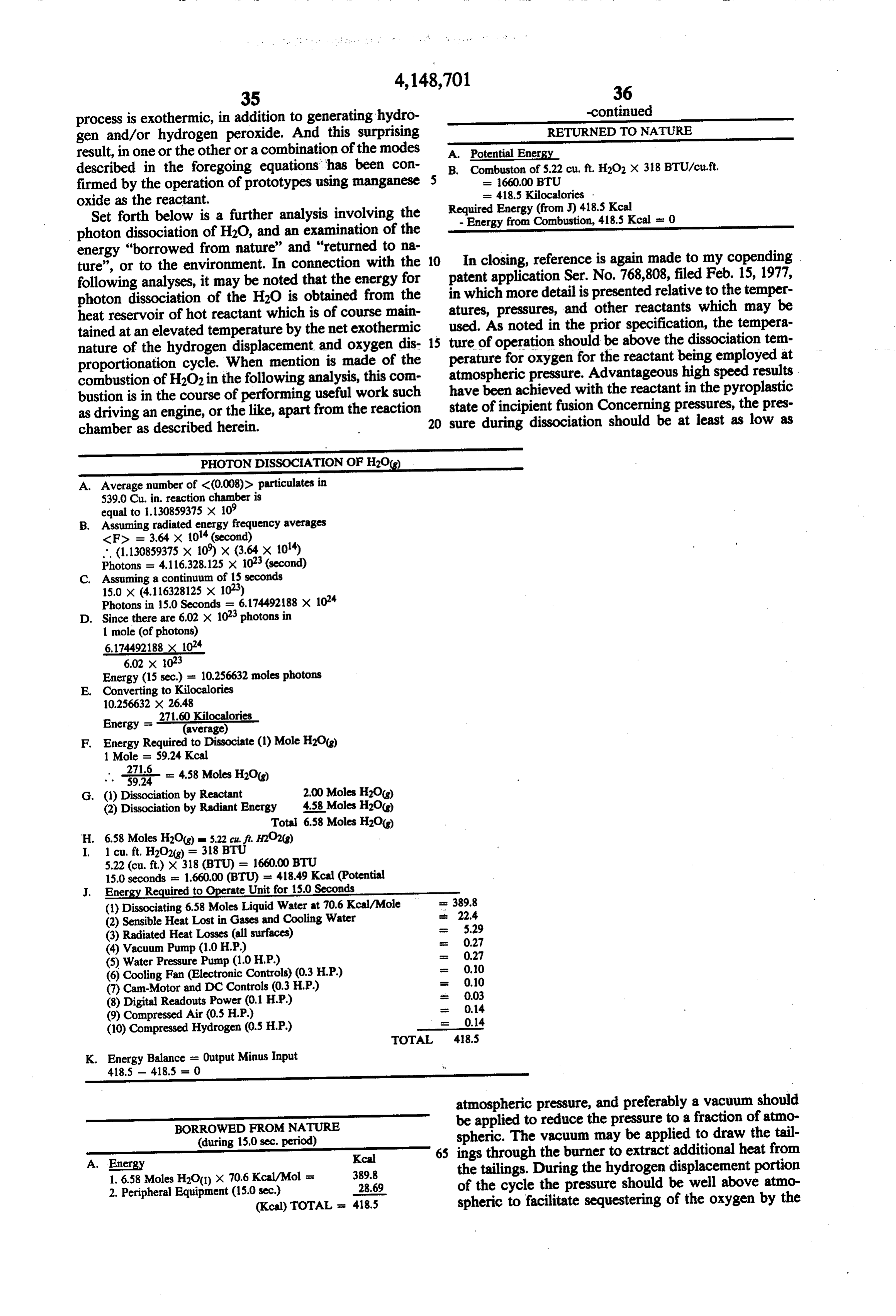
Page 36
reactant. Successful results may be achieved with reac The reaction chamber has an outer cylindrical stain tants such as MnO with gauge pressures of about 100 to less steel wall 310 secured to upper and lower stainless 130 or 150 and up to 500 pounds per square inch. Even steel end plates 312 and 314. The chamber 302 is pro higher pressures may be employed. Concerning the vided with a cylindrical ceramic liner 316 and upper active reactant, as mentioned in my prior copending and lower inner ceramic end plate 318 and 320. Suitable specification, it preferably includes at least one metal insulation 322 such as ceramic foam and an outer casing having a plurality of valence states. It should also have 324 are also provided.
an oxide which will, when subjected to water vapor at A series of coated wires 326 extend for most of the elevated temperature and/or pressure, and preferably length of the chamber 302 between upper and lower both, combine with the oxygen and displace the hydro 10 electrically conducting support members 328 and 330. gen in gaseous form exothermically. The reactant also As shown in FIG. 16, the wires 326 are made up of an preferably has the property of disproportionation or inner wire 332 of conducting or resistive material and dissociation to release the combined oxygen when the an outer coating 334 of ceramic material of radiation temperature is raised or preferably when the pressure is emitting material of one or more of the types previously reduced, and when the evolved oxygen is separated 15 described.
from the reactant. Advantageously, the heat required in The upper and lower wire supporting members 328 the disproportionation part of the cycle is significantly and 330 may be held apart by the elongated ceramic less than that generated in the exothermic portion of the member, and the metal rod 338 which extends into the cycle when the reactant combines with the oxygen in lower hollow end of ceramic member 336. The coated the steam and releases hydrogen, so the entire cycle is 20 wires 326 are heated up by the application of electricity exothermic. Also, the reactant should be susceptible of to power input conductors 340 and 342 to a temperature remaining in the pyroplastic state of incipient fusion in the order of 1000 Kelvin. This causes a certain during the change in state from one oxidation level to amount of thermal expansion in the wires, and by using another, and back again, under the described condi a suitable metal rod 338 which has a slightly higher tions. 25 coefficient of thermal expansion, the wires 326 may be Some of the metals and oxides thereof which fulfill maintained in operative positions relative to each other. the foregoing requirements include (1) antimony, (2) In the case of a process involving steam as the feed cesium, (3) barium, (4) iron, (5) manganese, (6) chro stock and where it is desired to have hydrogen gas and mium, (7) iridium, (8) nickel, and (9) thallium. Other H2O2 as the output product, air may be supplied either metals which have multiple valence states are known, 30 through input tube or pipe 304 and/or through separate but most of these have practical problems which pre input 344 to the apertured ring shaped mainfold 346 clude their use. Thus, for example, mercury has too low which is held in position by supports 348. Output prod a melting point, and its oxides are unstable. In the case uct is drawn off through pipe 350. of other metals having multiple valence states, their In practice, and as indicated in the block diagram of oxides may be poisonous, they may be caustic or are not 35 FIG. 18, air may be supplied to the reaction chamber available in practical or commercially available quanti 302 either through input 304 along with the input feed ties. Other metals having multiple valence states have stock such as steam, or through input 344 at the upper oxides which will not readily disproportionate. Combi zone of the reaction chamber. When the air is supplied nations of reactants satisfying the requirements indi through input 344, toward the upper end of 302, it com cated above may be employed in the form of alloys, bines with the previously-formed hydrogen, resulting eutetics, and with other materials to obtain desired tem from dissociation of the water vapor, to form H2O2. perature and mechanical properties. Other blocks shown in FIG. 18 include a source of FIGS. 14 and 15 are particularly useful in analyzing electrical power 354, a supply of liquid water at 356, a the apparatus of the present invention from a radiation steam formation unit 358, and a storage container 360 standpoint. FIG. 14 shows spectral radiant emittance, 45 for fuel gas such as gaseous hydrogen H2 and hydrogen or power in watts radiated at various wavelengths from peroxide H2O2. The supply line for water is indicated at a “black body" having a temperature of 1000 Kelvin, 362, and that for air at line 364.
while FIG, 15 is a similar plot showing photon emis As indicated by line 366, a portion of the fuel gas sion, or the number of photons emitted at various wave which is formed may be fed back to the steam formation lengths. The FIG. 14 plot drops off more rapidly than 50 unit 358 to increase the temperature of the water vapor that of FIG, 15 because shorter wavelength photons are being supplied to reaction chamber 302. After the unitis more energetic and have higher power. In accordance in operation for a short period of time, the steam is with known principles, the energy is directly propor supplied to the reaction chamber 302 at a temperature tional to the frequency and inversely proportional to the well above the intended operating temperature of reac wavelength. It may also be noted that, in the plots of 55 tion chamber 302 so that little or no electricity need be FIGS, 14 and 15 the visible range is from about 0.4 to supplied from the source 354. Thus, for example, with 0.7 microns. Accordingly for the temperature of 1000 steam being supplied at between 1100 and 1200' Kel Kelvin (about 727 Centigrade and about 1341 Fahren vin, the temperature of 1000 Kelvin desired within the heit), which is plotted in FIGS. 14 and 15, the radiation reaction chamber 302 may be sustained with the supply peaks in the spectrum at wavelengths somewhat longer 60 of very little or no electricity over line 368. and at frequencies slightly lower than the visible band. With reference to FIG. 20, the coated wires 326 are FIGS, 16, 17, and 18 show a system for applying shown supported by a screen 370 which may be made of radiant energy to a feedstock. In FIG. 17 the feedstock any suitable high temperature resistant conducting ma is applied to reaction chamber 302 by inlet tube 304 65 terial. The wires 326 are wovenin and out of the surface which is connected to manifold 306. Manifold 306 is of the screen 370 to form the array as shown in FIG, 17. supported by insulating ceramic material 308 which It may be noted that the frame or support members 328 may either by in the form of a ring or a series of support and 330 of FIG. 17 are shown as being formed of two ing blocks, parts. These two parts are open frame members which
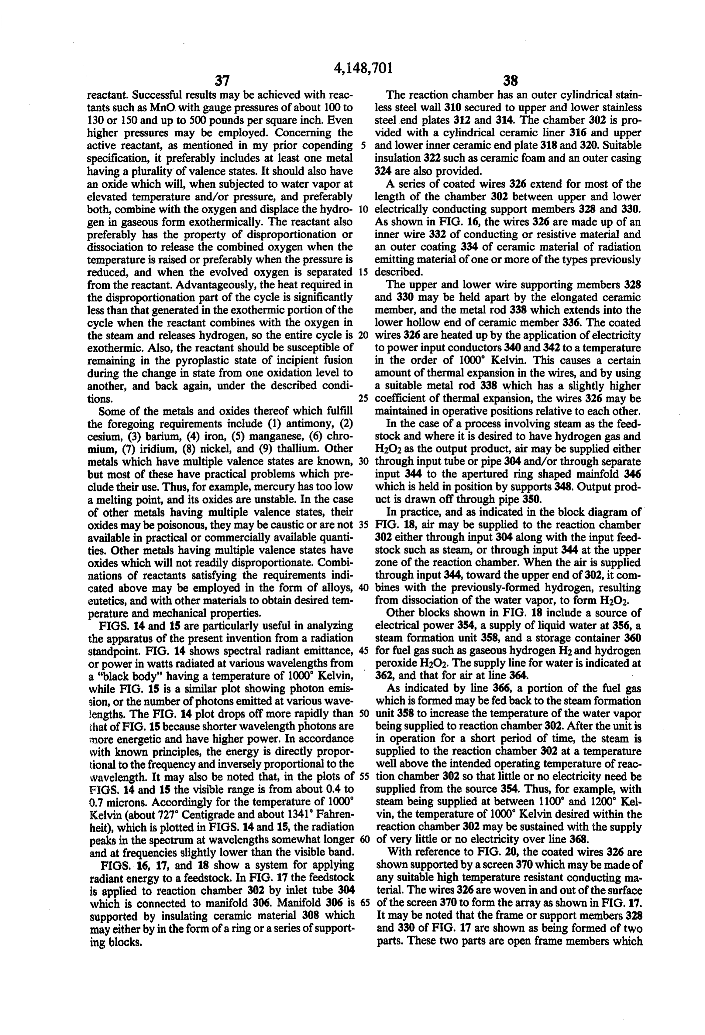
Page 37
clamp the screen 370 as shown in FIG. 20 and support may be noted that the emission, for Example No. 1 was it. If desired or if the conductivity of the particular approximately 0.69 microns corresponding to a fre coating employed in the system is relatively low, the quency of approximately 4.34 x 101 cycles per second. coated wires 326 may be scraped bare and welded This corresponds to a red color in the visible spectrum. contacts made at points such as those indicated at 372 in 5 Example No. 2 provides a yellow output light with a FIG. 20 to make better conductive engagement with wavelength of approximately 0.59 microns correspond the screen 370 by which electricity is initially supplied ing to a frequency of approximately 5.08 times 10' to these wires. It is also noted that, instead of using the cycles per second. Incidently, another yellow line is screen as shown in FIG. 20, the supporting structures produced by the materials of Example 12, with a wave 328 or 330 may be simple perforated plates with the 10 length of 0.61 micron, corresponding roughly to 4.91 coated wires 326 threaded through them. times 10 cycles per second.
Now, considering one specific example, the wires 326 Referring back to FIG. 17, one-half of the wires ex of FIG. 17 may be coated with the host and sensitizer tending from support 328 to support 330 are coated materials set forth in examples Nos. 1 and 2 of the 15 with material providing red output radiation such as examples set forth hereinabove in the present specifica- 15 specified in Example No. 1 referred to above, and one tion. half of the wires are coated with material providing a More specifically, before going into the example in yellow output radiation. These wires are threaded detail, it may be noted that various units are used in the through the supports 328 and 330 so as to be inter present specification in reference to the wavelength of spersed with one another so that the yellow and red the radiations which are employed. For reference pur- 20 output radiation wires are not grouped together but are poses and for ease in converting various units, it may be entirely interspersed with one another. noted that the visible range extends from about 4000 When feedstock is supplied to the reaction chamber Angstrom units to 7000 Angstrom units, with an Ang- 302, the radiation will be directed from the wires to the strom unit being equal to 108 centimeters. Expressed medium and the radiation of different frequencies will in microns this visible range corresponds to wave- 25 impinge upon the discontinuities provided by the feed lengths from 0.4 to 0.7 microns, with a micron being stock vapors and will beat with one another and will be equal to 10-centimeters. Similarly, when millimicrons converted into sum and difference frequencies. More are employed to measure wavelength, they correspond specifically, considering examples Nos. 1 and 2, the to 10-7 centimeters, and the visible spectrum range is frequency for the red radiation of Example 1 was ap from 400 to 700 millimicrons. 30 proximately 4.34 times 101 cycles per second, and the It may also be noted, in converting frequency to frequency for Example No. 2 was approximately 5.084 wavelength and vice versa that the frequency of light is times 101 cycles per second. One frequency which will equal to 3 times 1010 centimeters, and that the product be formed as these radiations impinge on the feedstock of frequency and wavelength is equal to the velocity of will be the sum frequency equal to approximately 9.42 light. Accordingly, using this simple expression that the 35 times 10 cycles per second. This corresponds to a product of the frequency times the wavelength is equal wavelength of about 0.32 microns, in the near ultravio to the velocity of light, easy conversion may be made let frequency spectrum. Water vapor has a number of from frequency to wavelength, and vice versa. For absorption peaks in the near ultraviolet frequency spec convenience, reference is also made to Table I which trum and these peaks are broadened by the elevated indicates the location of the visible light band relative to 40 temperature present at 1000 Kelvin at which the reac the infrared and ultraviolet frequency bands, in addition tion chamber 302 is operated. Accordingly, in addition to the remainder of the electromagnetic radiation spec- to the dissociation action produced by the direct radia trum. tion at the red and yellow frequency bands, the power
TABLE I
TABLE 1-2
The Wavelength, Frequency, and Energy of Typical Electromagnetic Radiation
Approximate Typical Frequency, Wave Number, Energy, Description Wavelength, A cycles/sec cm 1 kcal/einstein Radio wave 1.00 x 10³(1000 m) 3.00 x 10(300 kc) 1.00 x 10 0.0000000286 Short-wave radio 1.00 x 101 (10 m) 3.00 x 10(30 Mc) 1.00 x 10³ 000000286 Wawe
Microwave 1.00 x 10(1 cm) 3.00 x 10¹⁰ 1.00 0.00286 Far infrared 1.00 x 10(10) 3.00 x 10¹³ 1.00 x 10³ 2.86 Near infrafed 1.00 x 10(1) 3.00 x 10¹⁴ 1.00 x 10 28.6 Visible light
Red 7.00 x 10(700 mp) 4.28 x 10¹⁴ 1.43 x 10 40.8 Orange 6.20 x 10 484 x 101 1.61 x 10' 46.1 Yellow 5.80 x 10 5.17 x 10¹⁴ 1.72 X 10. 49.3 Green 5.30 x 10 5.66 x 10¹⁴ 1.89 x 10 53.9 Blue 4.70 x 10 6.38 x 101 2.13 x 10 60.8 Photo Violet 4.20 x 10 7.4 x 10¹⁴ 2.38 x 10 68.1 chemistry Near ultraviolet 3.00 x 10 1.00 x 10¹⁵ 3.33 x 10 95.3 region Far ultraviolet 2.00 x 10 1.50 x 10¹⁵ 5.00 x 10 142.9 Schumann ultra- 1.50 x 10³ 200 x 1015 6.67 x 10 1906 violet
Long X-ray 3.00 x 10² 1.00 x 10¹⁶ 3.33 x 10 953.0 Radiation Short X-ray 1.00 3.00 x 10⁸ 1.00 x 10⁸ 285,910 } chemistry Gamma ray 1.00 x 10⁻² 3.00 x 10²⁰ 1.00 x 10¹⁰ 28,591,000 region
With the foregoing background, reference is again made to examples Nos. 1 and 2 of the 15 numbered examples set forth earlier in the present specification. It ful ultraviolet radiations will have a strong dissociative
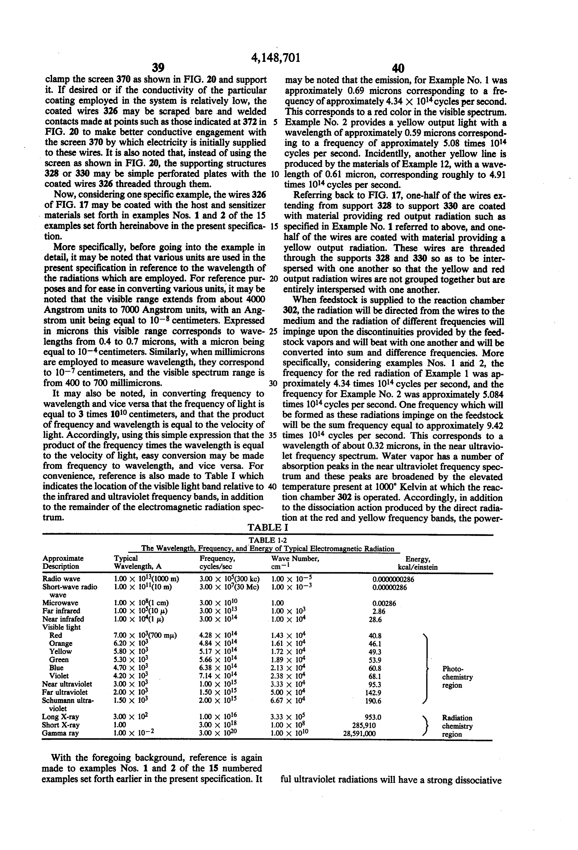
Page 38
effect on the water vapor being transmitted through the It is also particularly to be noted that through the use reaction chamber 302. Incidentally, the energetic nature of coated wires, the amount of initial heat input required of the radiations in the near ultraviolet may be noted to raise the reaction chamber to operating temperature from the far right-hand column in Table No. 1 in which conditions, is greatly reduced. the radiation in the near ultraviolet is shown to have an For completeness, one set of dimensions for the wires energy level in the order of double that in the red and 326,384 and 386 will now be given. The overall diame yellow regions of the visible spectrum. ter of the coated wires may be 0.00257 inch, and the Attention is also directed to the plot of FIG. 25 show diameter of the inner metal wire is 0.00157 inch with the ing the absorption characteristic for hydrogen peroxide coating being about 0.0005 inch thick, adding about H2O2 which is being formed in the radiation chamber 10 one-thousandth of an inch to the diameter. The inner 302. More specifically, it may be seen that the absorp metal wires may, for example, be made of tungsten or tion coefficient increases rapidly from the near ultravio other metal having a relatively high melting point and let range of 3000 Angstroms, or about 0.3 microns, to adequate strength at 1,000 Kelvin.
the far ultraviolet range toward the left of FIG. 21. FIGs. 22 and 23 show an alternative arrangement for Accordingly, with near ultraviolet radiation being em 15 applying high frequency radiation to feedstock supplied ployed in the chamber of FIG. 17 (reaction chamber to a reaction chamber. In FIG. 22 the reaction chamber 302) to dissociate water vapor, it may be noted that the perse is made up of two hemispheres 402 and 404 which desired product gas H2O2 will be little affected and will are secured together by bolts 406 which extend through be essentially transparent to this near utraviolet radia the mating flanges 408 and 410 of the hemispheres 402 tion and will thus remain in its H2O2 chemical state, 20 and 406. An outer sheet metal housing 412 is provided after it is formed, without adverse effect from the near to enclose the unit and to support the various enclosed ultraviolet radiation. elements of the system. Thus, for example, the hemi F.G. 19 shows a alternative reaction chamber 376 spheres 402 and 404 are supported from brackets 414 which is divided into an upper section 378 and a lower secured to the housing 412. Between the reaction cham section 380. Dividing these two sections of the chamber 25 ber 402, 404 and the housing 412 is suitable insulation is a perforated ceramic plate 382. In addition, two dif for 416 of the ceramic foam insulation type. ferent sets of coated wires 384 in the upper section and Feedstock is supplied to the reaction chamber 402, 386 in the lower section, are provided. These two sets of 404 through input pipe 458, and product gases are with wires are electrically interconnected by the links 388 drawn from the reaction chamber through pipe 420. which extend through the ceramic plate 382 and join 30 Input radiation is supplied to the reaction chamber the lower support 390 for the upper set of wires 384 to 402,404 through the window 422 which may, for exam the upper support 392 for the lower set of wires 386. ple, be made of high temperature resistant quartz glass. Apart from being divided into two chambers with two FIG. 23 is taken along line 23-23 of FIG. 22. Shown sets of different coated wires in the upper and lower to advantage in FIG. 23 are the two lasers 424 and 426 portions 378 and 380 of the reaction chamber 376, the which direct coherent radiation of different colors chamber of FIG. 19 is generally similar in configuration through the window 422 into the reaction chamber 402, to that of FEG, 17. 404 which has a highly polished interior surface. One of With regard to the nature of the coating on the wires the laser's 424, 426 is a ruby laser with output radiation 384 and 336, the upper wires 384 are coated as described in the red spectral region, while the other laser is an above in connection with FIG. it to produce ultravio yttrium aluminum garnet, or Yag laser with output let radiation. radiation in the green frequency band. These lasers are The lower set of wires 386, however, are coated to directed at an acute angle through the window 422 so provide strong output radiation in the infrared radiation that the radiation of the two lasers beat to produce a spectrum, as disclosed hereinabove in connection with higher frequency in the ultraviolet spectrum, as dis examples A, B, and C. Accordingly, the arrangement of 45 cussed and developed hereinabove in connection with FIG. 19 is organized to provide powerful radiation in the radiation from the wires of FIGS. a7 and 19. Ac portion 380 which will impinge vigorously on the feed cordingly, the feedstock supplied to the reaction cham stock and provide an initial very substantial dissociative ber through the pipe 418 will be irradiated not only with effect on the water vapor. Then, in the upper portion the red and green direct laser illumination, but also by 378 of the reaction chamber the dissociation of the 50 the beat frequencies which arise when the red and green water vapor is continued, but at a frequency in the near radiation impinge on the discontinuities provided by the ultraviolet range which is clearly at a frequency spec feedstock materials supplied to the chamber. trum with respect to the hydrogen peroxide, H2O2, It may also be noted that in all of the embodiments product gas which will not adversely affect or dissoci decribed herein, where additional oxygen is supplied, ate it. The combined effect of the two stage radiation and hydrogen peroxide, or H2O2, is formed, this reac chamber with different radiation frequencies being ea tion is exothermic and supplies heat to the reaction ployed in each of the two chambers, is such as to maxi chamber. This factor is useful in increasing the effi mize the production of the desired output gas. ciency of the processes, and contributes to the self-sus Of course, in connection with FIGs, 16 through 23, taining nature of the processes, as discussed above. two specific examples of reaction chamber arrange 60 On a general basis, the processes described herein ments employing radiation to produce desired product provide a mechanism for the transformation of low gases have been set forth. It is to be understood that grade thermal radiation into specific coupled modes of through the examination of the spectral absorption intense monochromatic radiation providing new higher characteristics of the feedstocks and products, and by frequencies and shorter wavelengths with considerably suitably providing radiation within the reaction cham 65 increased power.
ber matched to the characteristics of the feedstock and The energy change is accomplished through the cre the product, many other similar combinations may be ation of controlled spatial harmonics beating together developed by those skilled in the art. while passing through media discontinuities within a
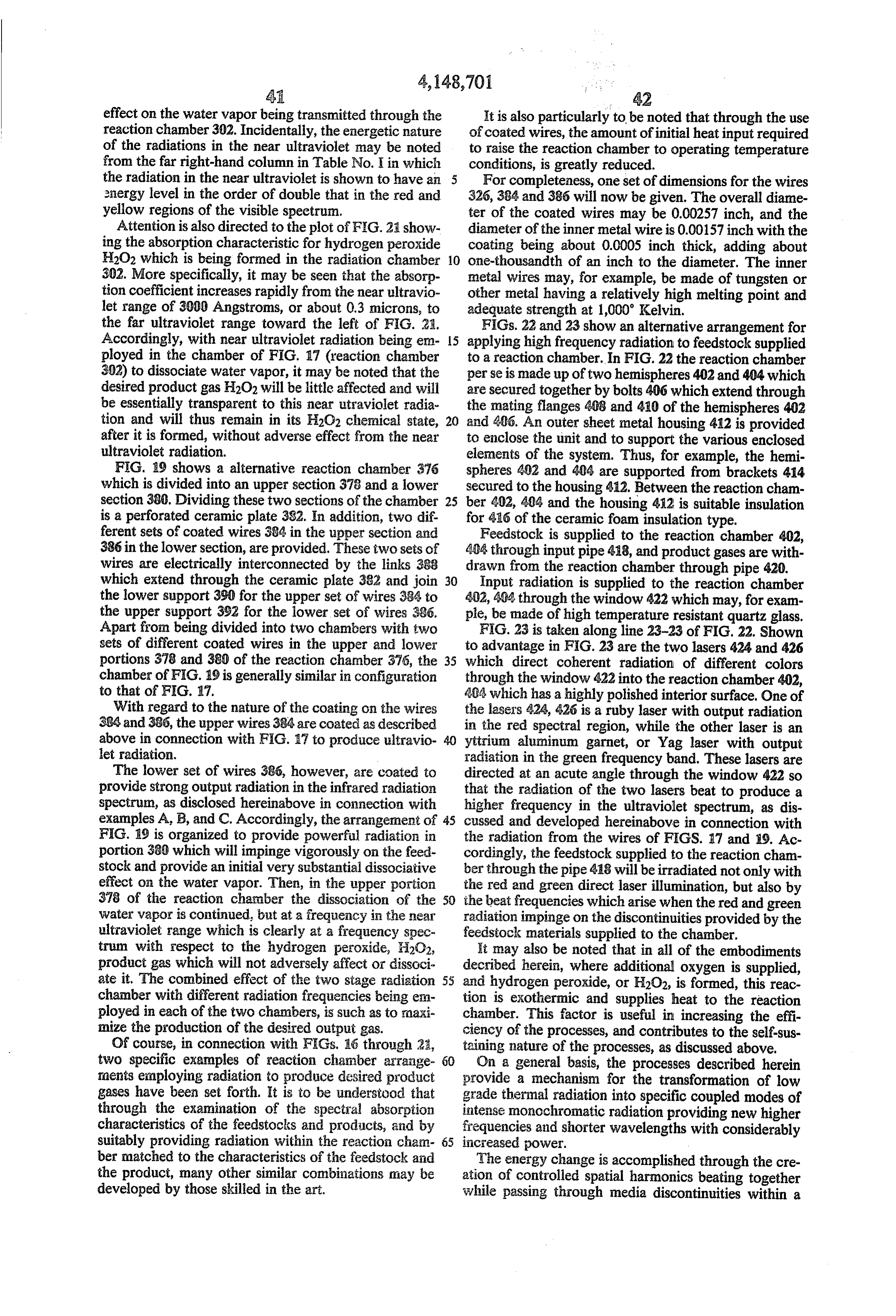
Page 39
non-linear medium. The effect is much like a parametric ing means for operating said inchamber 3. An apparatus as defined claim i further compris at elevated tem amplifier which controls the disposition of the electro perature and pressure.
magnetic energy conveyed by the waves. On a compre hensive basis, the transformation of the broad black 5 ing4.means An apparatus as defined in claim 3 further compris for preheating said feedstock to a tempera body radiation into specific monochromatic frequencies ture substantially above the operating temperature of of high energy which are matched to the absorption bands of the feedstock and to the transmission bands of said chamber.
the product, make for process efficiencies which are feedstock 5. An apparatus as defined in claim 1 wherein said extremely high. has a plurality of absorption bands, and 10 wherein a plurality of different radiation generating
With regard to the operating temperatures and pres sures for the apparatus of FIGS. 16through 19, and that means stock are provided for applying energy to said feed at a plurality of said absorption bands.
of FIGS. 22 and 23, the temperatures and pressures are 6. An apparatus as defined in claim 1 wherein said less critical than for the embodiments disclosed earlier in the present case. In general, in order to provide radia 15 means andgenerating radiation means includes host and sensitizer a plurality of different host material means tion in the desired spectral range the apparatus of FIGS. are provided for absorbing energy at various frequen 16 through 19 should be operated at a temperature in cies and for exciting said sensitizer material to radiate the order of 1000' Kelvin; however, other temperatures energy at different frequencies corresponding to the may be employed which produce adequate radiation at high absorption regions in the characteristic of said the desired frequencies, and a departure of 100" or 200 20 feedstock.
above or below 1000 K. would be operative, it is ex 7. An apparatus as defined in claim 1 further compris pected, with radiation drop off toward the lower end of 1ng:
this temperature range and possible materials failure means for supplying steam to said chamber as the problems toward the upper end of the range. Concern feedstock; and ing the embodiment of FIGS. 22 and 23, a lower tem 25 means for supplying additional air to said chamber for perature such as 250 F., above the boiling point for combination with the released hydrogen to form water at the pressure which is employed, would be hydrogen peroxide.
adequate. 8. An apparatus as defined in claim 1 further includ Concerning pressures, somewhat lower pressures are ing means for supplying water vapor at elevated pres adequate, as compared with the embodiments involving 30 sure as said feedstock.
the use of metallic oxides, and no change in pressure is 9. An apparatus as defined in claim 1 further compris needed. For the embodiments of FIGS. 22 and 23, a ing means for supplying said feedstock on a substan gauge pressure of 3 or 4 pounds would be adequate, tially continuous basis.
although higher pressures of up to several hundred radiation 10. An apparatus as defined in claim 1 wherein said pounds, for example, could be employed where higher 35 applying means includes a plurality of con fuel gas reservoir pressures are desired. Similar pressure are ducting wires, and wherein host and sensitizer material considerations are applicable to the apparatus of FIGS. located on the outer surface of said wires. 16 through 20. 11. An apparatus as defined in claim 1 further com In the foregoing spcification a number of examples of prising:
reactants, host/sensitizer combinations, and radiation 40 means tion for withdrawing product gas from said reac chamber, and wherein said product gas is sub frequencies have been set forth, and the principles for stantially transparent to the radiation in said reac their selection to implement particular needs have been tion chamber.
defined; accordingly, the scope of the present invention is not restricted to the specific illustrated example, but is 45 ing12.means
An apparatus as defined in claim 1 further includ for supplying water vapor to said reaction to be defined only by the appended claims: chamber as said feedstock, and further comprising What is claimed is: means for supplying oxygen to said reaction chamber to 1. An apparatus for applying high frequency energy form hydrogen peroxide.
to a feedstock comprising: 13. An apparatus as defined in claim 1 wherein said a reaction chamber; radiation applying means is a series of wires coated with means for supplying feedstock to said reaction cham host and sensitizer material.
ber, said feedstock having at least one predeter 14. An apparatus as defined in claim 1 wherein said mined energy absorption band; radiation applying means includes means applying at means for applying high intensity radiation to said least two narrow bands of intense high frequency radia reaction chamber, including means located within 55 tion.
said reaction chamber for generating radiation 15. An apparatus as defined in claim 1 wherein said within said absorption band by transitions from a means for applying high intensity radiation to said reac predetermined excited energy state to a lower en tion chamber includes resistive wires, and host and ergy state, and associated means for raising said sensitizer material coated on said wires.
radiation generation means to an excited state; and 16. An apparatus as defined in claim 15 further com means for supporting a large plurality of said radia prising means for heating said wires.
tion generating means within said reaction cham 17. An apparatus as defined in claim 1 wherein two ber to flood said reaction chamber with intense different radiation generation means are provided for radiation at the frequency or frequencies corre generating intense high frequency energy at two respec sponding to said energy level transitions, and alter 65 tively different frequencies.
the composition of said feedstock. 18. An apparatus as defined in claim 17 wherein said 2. An apparatus as defined in claim 1 further compris reaction chamber has an input section and an output ing; insulation means enclosing said chamber. section, and wherein means are provided for applying
Page 40
said high frequency energy of said two different fre sneans for applying the heat generated as said hydro quencies to said input and output sections, respectively. gen peroxide is formed toward maintaining said 19. An apparatus as defined in claim a wherein said reaction chamber at an elevated temperature. means for supplying feedstock to said reaction chamber 26. A process for applying high frequency energy to constitutes means for supplying water vapor to said 5 feedstock comprising:
feaction chamber; and further comprising reas for supplying feedstock to a reaction chamber having an supplying additional air to said reaction chamber to input section and an output section, said feedstock form hydrogen peroxide and concurrently suppiy inea; having predetermined absorption bands; to said reaction cihamber; and means for drawing off product fuel gases including hydroger peroxide frog 10 supplying within high intensity radiation at a first frequency at least one absorption band of said feed said reaction chamber.
20. An apparatus for applying high frequency energy stock to the input section of said reaction chamber to a feedstock comprising: to dissociate at least a portion of the feestock sup a reaction chamber; plied to said radiation chamber and to form desired product gas; and means for supplying feedstock to said reaction cham ber; said feedstock having a predeterrained absorp tionsupplying high intensity radiation to the output sec tion characteristic and said feedstock constituting a within anotherreaction of said chamber at a second frequency absorption band of said feedstock and to discontinuous medium within said radiation chair ber; which said product gas is transparent, said second fre means applying high intensity radiation to said reac guercy,queracy being significantly different from said first fre tion chamber at a first frequency; and to complete the desired reaction.
means applying high intensity radiation to said reac vapor comprising: apparatus for generating hydrogen from water tion chamber at a second frequency wherein the a reaction chamber;
sum of said first frequency and said second fre means for supplying water vapor to said reaction quency is a predetermined third frequency which is chamber, said water vapor having predetermined generated when said radiation inpinges on said energy absorption band or bands; feedstock, and wherein said feedstock has a higia means for supplying high intensity radiation to said absorption characteristic for radiation of said third frequency, whereby said feedstock absorbs a sub reaction chamber, including means located within stantial portion of the radiation which is generated 30 said reaction chamber for generating radiation at as the surn of said first and second frequencies. one or more selected narrow frequency bands 21. An apparatus as defined in clair in 20 wherein said within said absorption band; third frequency is in the ultraviolet frequency range. means for supplying energy to excite said radiation 22. An apparatus for applying high frequency energy generation means;
to a feedstock as set forth in cairn 22 wherein said 35 naeand for supporting a plurality of said radiation means for applying high intensity radiation to said reac generating means within said reaction chamber to tion chamber includes first and second sources of iases flood said reaction chamber which intense radia radiation operating at respectively different frequencies tion within said absorption band or bands to split and radiating into said reaction chamber. said water vapor into hydrogen and oxygen; and 23. A process for applying high frequency energy to 4 neas for drawing off hydrogen and or hydrogen a feedstock comprising: peroxide from said reaction chamber. supplying feedstock to a reaction chamber; 28. As apparatus as defined in claim 27 wherein said applying high intensity radiatioia at a first frequency radiation supplying means includes means for generat to said reaction chamber; ing high frequency radiation at two distinct high fre applying additional high intensity irradiation to said quencies.
reaction chamber at a second frequency to eat 23. An apparatus as defined in claim 27 further com with said first frequency radiation in the presence prising means for supplying air to said reaction chamber of discontinuities in said reaction chanber created to 30. increase the formation of hydrogen peroxide. An apparatus for applying high frequency energy by the presence of said feedstock to generate a third frequency lying in the ultraviolet frequency to a feedstock comprising:
band which is the sum of the frequency of said first a reaction chamber;
radiation and the frequency of said second radia ineans for Supplying feedstock to said reaction cham tion; and se:
drawing off product gas from Said reaction chatter. faeans applying high intensity radiation to said reac 24. A process as defined in ciaia 23 wierein said 5 5 tion chamber at a first frequency; feedstock is water vapor and further coing rising the aneans applying high intensity radiation to said reac step of supplying additional air to the reaction charaber tion chamber at a second frequency to beat with to form hydrogen peroxide, and to thereby supply heat said first frequency radiation in the course of inter to said reaction chamber. acting with Inedia discontinuities within the non 25. An apparatus for forning hydrogen peroxide 6 linear medium formed by said feedstock within said comprising: reaction chamber; and a reaction chamber; said means for supplying high intensity radiation to high frequency radiation neans mounted withi said said reaction chamber at said first and second fre reaction charaber for forning gaseous hydroge: queficies constituting conducting wires coated from steam at an elevated temperature within said with host and sensitizer material. reaction charter; 31. A nethod for applying high frequency energy to means for supplying air for combination with the a feedstock comprising the steps of:
gaseous hydrogen to form H2O2, and supplying water vapor to a reaction chamber;
Page 41
applying high intensity radiation in an absorption an energy output characteristic when in the excited band of said water vapor to said reaction chamber state which corresponds to at least one energy to dissociate said water vapor, by heating wires absorption region of said water vapor; coated with host and sensitizer material to an ele host material associated with said sensitizer material vated temperature; 5 for absorbing energy from said reactant and for supplying additional air to said reaction chamber to exciting said sensitizer, whereby the broad radia form hydrogen peroxide and concurrently supply tion versus frequency spectrum of said reactant is heat to said reaction chamber; and concentrated and applied to said water vapor in the drawing off product gases including hydrogen perox absorption band or bands of said water vapor; ide from said reaction chamber. 10 means for drawing off the hydrogen and/or hydro 32. An apparatus for generating hydrogen and/or gen peroxide released when said reactant seques hydrogen peroxide exothermically comprising: ters oxygen from said water vapor, and when mole a reactant comprising a metal or oxide thereof, said cules of water vapor are split up by radiant energy metal having a plurality of oxidation states, said 15 from said sensitizer material; reactant being capable above a predetermined ele means for terminating the application of water vapor vated temperature and a predetermined elevated to said reactant;
pressure of sequestering oxygen from steam and means for terminating the drawing off of hydrogen releasing hydrogen gas exothermically, with the and/or hydrogen peroxide obtained by the seques production of a predetermined amount of heat, and tering of oxygen from said water vapor; capable of releasing oxygen in the absence of signif. 20 means for removing the gaseous oxygen and other icant levels of gaseous oxygen with heat input less residual gases from the vicinity of the reactant and than said predetermined amount of heat; for disproportionating or dissociating the oxygen means for heating said reactant and maintaining said from the reactant;
reactant above said predetermined elevated tem means for supplying additional air to the vicinity of perature and above the atmospheric pressure dis 25 the hydrogen gas being formed to combine with proportionation temperature for oxygen for at least the hydrogen to form hydrogen peroxide; one of said oxidation states; means for establishing spaces in the vicinity of said means for applying water vapor at said predeter heated reactant;
mined elevated pressure to said reactant; said water 30 means for directing said feedstock through said vapor having a predetermined energy absorption spaces; and versus frequency characteristics; means for locating said host material and said sensi sensitizer material located in proximity to said reac tizer material along the boundaries of said spaces. tant and exposed to said water vapor, and having
Provenance
- Collection
- Cited prior art
- Original PDF
- patentimages.storage.googleapis.com →
- Filed
- 1977-09-19
- Pages
- 41
- Method
- pdftotext (the PDF's own text layer) + pdftoppm 300dpi page scans
- Source
- Google Patents bibliographic record
- Granted
- 1979-04-10
- Inventors
- Sam L. Leach
- Transcribed from
- patentimages.storage.googleapis.com →