patent · US4287942
Heat storage apparatus
8 September 1981
Page 1
United States Patent (19) (11) 4,287,942 Whitman 45) Sep. 8, 1981
(54) HEAT STORAGE APPARATUS OTHER PUBLICATIONS 76 Inventor: William C. Whitman, 3 Fourth St., Univ. of Delaware, Institute of Energy Conservation New Brunswick, N.J. 08901 Circular, Summer 1977.
21 Appl. No.: 920,962 Primary Examiner-Samuel Scott
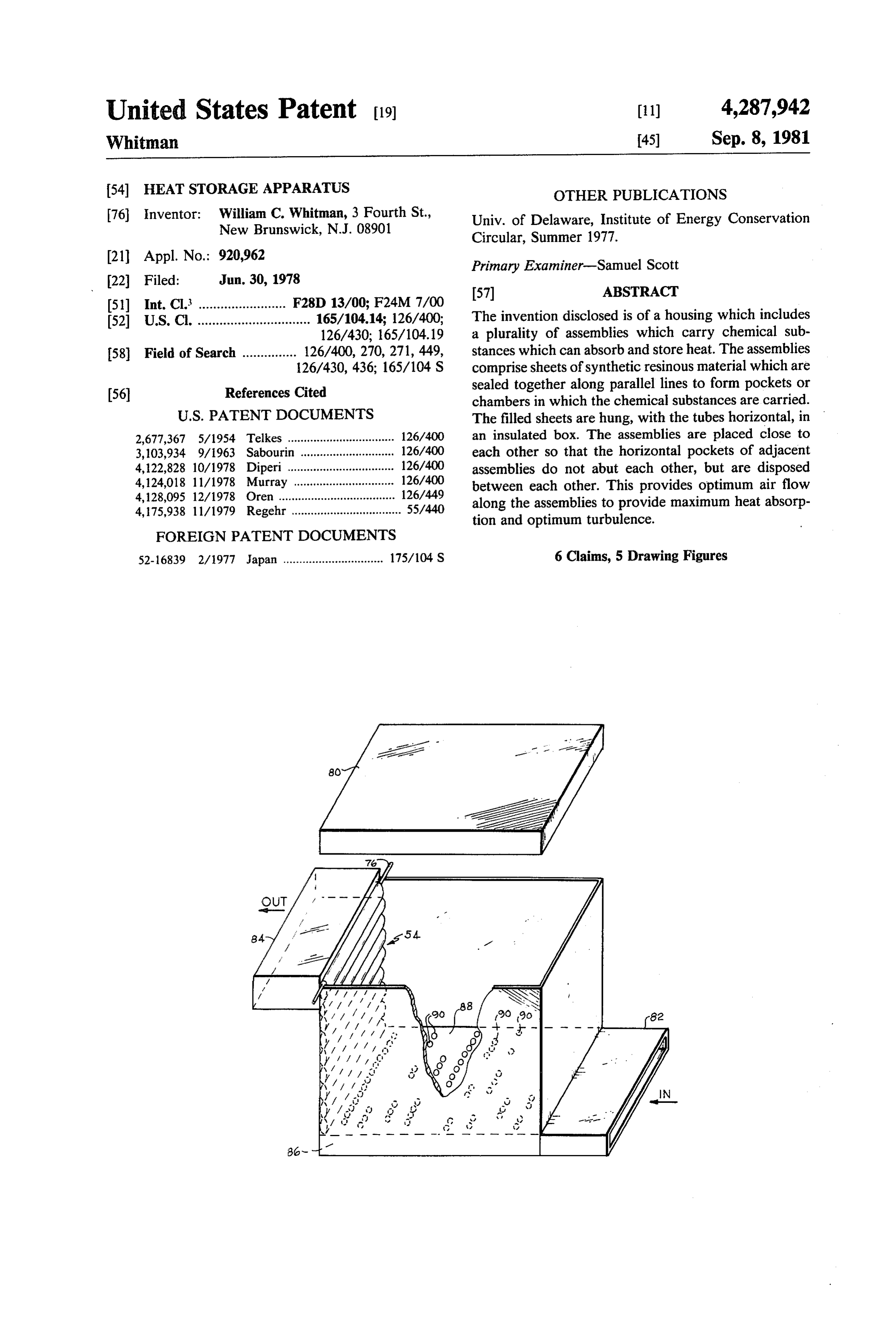
52 U.S. Cl. ............................... 165/104.14; 126/400; The invention disclosed is of a housing which includes 126/430; 165/104.19 a plurality of assemblies which carry chemical sub 58) Field of Search ............... 126/400, 270, 271, 449, stances which can absorb and store heat. The assemblies 126/430, 436; 165/104 S comprise sheets of synthetic resinous material which are (56) References Cited sealed together along parallel lines to form pockets or chambers in which the chemical substances are carried.
2,677,367 5/1954 Telkes ................................. 126/400 an insulated box. The assemblies are placed close to 3,103,934 9/1963 Sabourin ............................. 126/400 each other so that the horizontal pockets of adjacent 4,122,828 10/1978 Diperi ................................. 126/400 assemblies do not abut each other, but are disposed 4,124,018 11/1978 Murray ............................... 126/400 between each other. This provides optimum air flow 4,128,095 12/1978 Oren .................................... 126/449 along the assemblies to provide maximum heat absorp 4, 175,938 11/1979 Regehr .................................. 55/440 tion and optimum turbulence.
FOREIGN PATENT DOCUMENTS
52-16839 2/1977 Japan ............................... 175/104 S 6 Claims, 5 Drawing Figures
Page 2
Drawing sheet — no readable text.
Page 3
Drawing sheet — no readable text.
Page 4
gether in the housing 50, with the rods 76 supported in
HEAT STORAGE APPARATUS holes in the housing walls or simply set on top of the framing of the housing, as illustrated schematically in
BACKGROUND OF THE INVENTION FIG. 6.
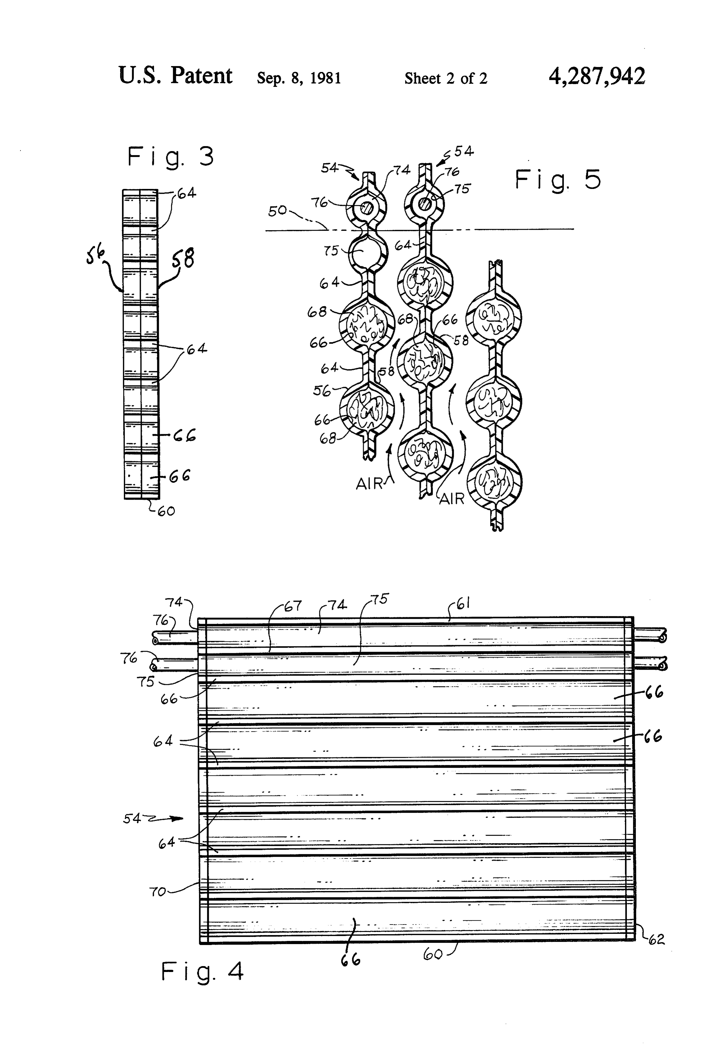
There is considerable activity in the field of solar 5 Preferably, the carriers 54 are arranged in the housing energy at the present time, and one portion of the typi 50 so that the chemical-containing pockets 66 of adja cal system, the storage unit, as presently known, is too cent carriers are not in contact with or adjacent to each bulky and expensive. The present invention provides a other, but are offset from each other so that, as to adja system and method of manufacture which are relatively 10 cent carriers, as seen in FIG. 5, the pockets of one are simple, inexpensive, and provide a storage unit which adjacent to or aligned with the spaces between the occupies minimal space. pockets of the other. This can be achieved by inserting DESCRIPTION OF THE DRAWINGS the rods 76, of adjacent carriers, first in rod chamber 74 and then in rod chamber 75 and then in chamber 74, etc.
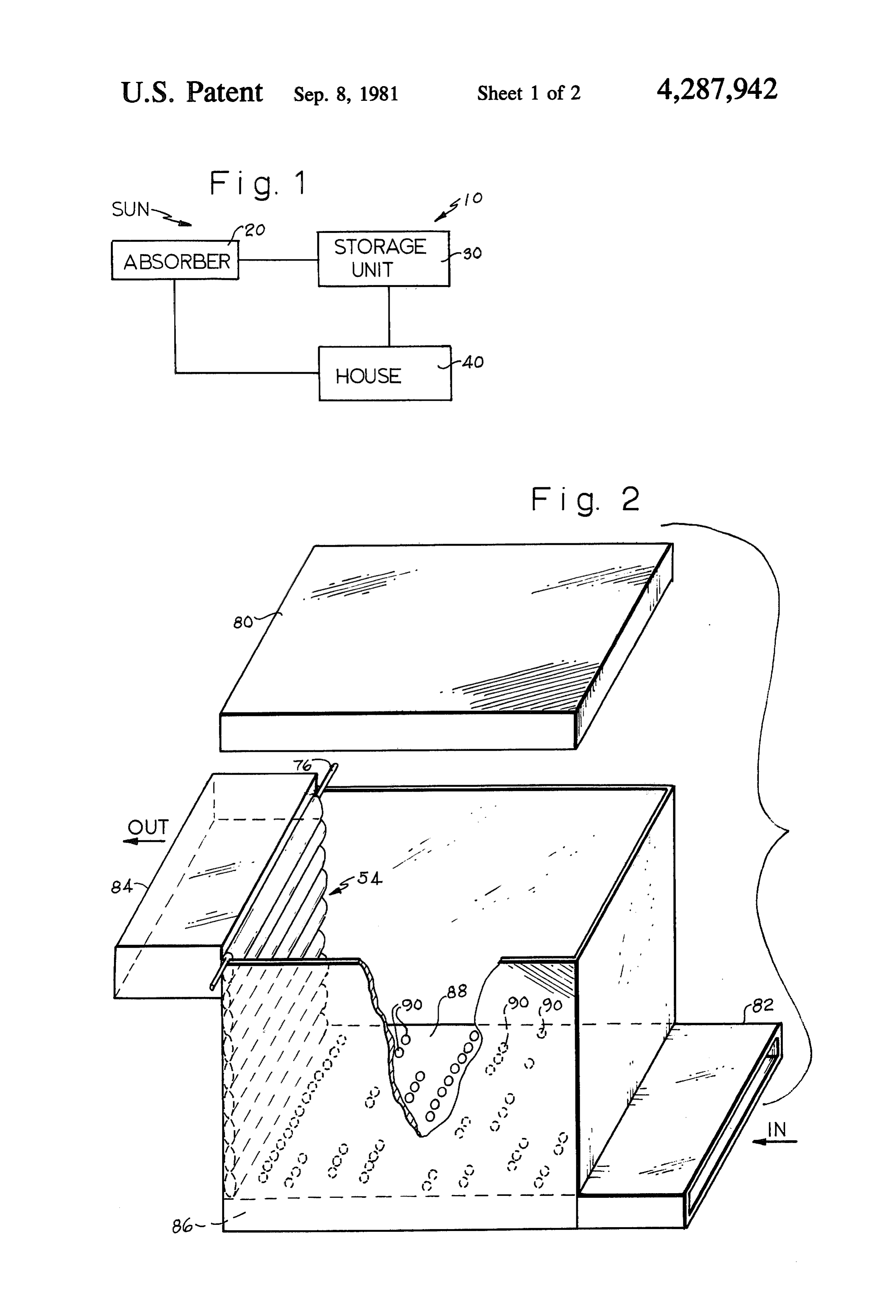
FIG. 1 is a schematic representation of a solar heating 15 The housing 50 is provided with a cover 80 and with system embodying the invention; suitable inlet and outlet ducts 82 and 84. The inlet duct FIG. 2 is a perspective, exploded view of the storage 82 may be provided along one side of the housing 50 unit of FIG. 1; adjacent to the bottom, and the outlet duct 84 may be FIG. 3 is a side elevational view, considerably en provided along the opposite side of the housing adja larged, showing two sheets of film secured together to 20 cent to the top of the housing. The inlet duct extends make up a storage assembly, before being filled with from the solar heat absorber 20, and the outlet duct runs chemicals; to the area 40 to be heated.
FIG. 4 is a front elevational view of a storage assem In addition, an air distribution plate 86 is coupled to bly ready for mounting in the storage unit; and the inlet duct and is disposed adjacent to the base of the FIG. 5 is a side view of several storage assemblies, housing 50. The air distribution plate is closed except shown in section, generally as they would be arrayed in for a top plate 88 having an array of apertures 90, the storage unit and illustrating air flow along the as through which the inlet air is distributed upwardly semblies.
between the carriers 54.
DESCRIPTION OF THE PREFERRED In operation of the invention as illustrated schemati EMBODIMENTS 30 cally in FIG. 5, air flows upwardly between the carriers A typical solar energy heating system 10, shown in 54 and the positioning of the chambers 66, as shown and FIG. 1, includes a solar energy absorber 20 which ab described, provides a serpentine air flow path which sorbs heat from the sun and transmits it through a suit creates an optimum degree of turbulence, and prevents able medium such as water or air to a storage unit 30 the formation of static layers of air between the cham where the heat is stored until needed, at which time it is 35 bers.
circulated through the area to be heated, such as a home It is noted that the spacing between storage chambers 40, and then it is recirculated through the absorber 20. 66 in each storage assembly 54 may be suitably adjusted The storage unit 30, according to the invention and for each installation.
referring to FIGS. 2, 3, 4, and 5, includes a housing or What is claimed is:
chamber 50 of any suitable size having side walls, a base, 40 1. Storage apparatus for thermal energy comprising and an open top which is closed by a cover 80. A plural a housing, ity of storage assemblies 54 which are used as chemical inlet and outlet means in said housing directing a flow carriers are placed in the housing. Each assembly 54 is of fluid, for use in performing a heat transfer opera made up of two sheets 56 and 58 of a suitable non-por tion, along a path through said housing, ous, synthetic resinous material such as polypropylene 45 a plurality of thermal storage assemblies disposed in a or the like. series adjacent to each other and generally parallel In making the carriers 54, the two sheets 56 and 58, of to each other and positioned so that fluid flows the same size and shape, are placed together and sealed from said inlet means to said outlet means between along the abutting three sides 60, 61, 62 to form a closed and along said storage assemblies, said storage as container open only at filling edge 70. The two sheets 50 semblies being adapted to take part in a transfer of are also sealed together along parallel lines 64, suitably thermal energy with said fluid, spaced apart, which extend parallel to the sealed side each storage assembly comprising a sheet-like mem edges 60 and 61 to thereby form elongated chambers or ber formed with a plurality of parallel, elongated, pockets 66 between the sheets 56 and 58 and between generally tubular pockets containing a chemical the seal lines 64. Two spaced-apart parallel chambers or 55 substance which can store and give up thermal pockets 74 and 75 are also formed by seal line 67 be energy, said pockets forming a plurality of parallel tween edge 61 (the top edge) and the first chamber 66 to curved corrugations spaced apart along the length receive mounting rods 76. The chambers 66 are filled of and in the outer surfaces of said sheet-like mem with a chemical 68, a thermal energy storage chemical ber, said pockets being disposed generally trans Such as a salt-hydrate or a eutectic mixture, and then 60 they are sealed along the filling edge 70 to form the verse to said path of fluid flow through said hous sealed chemical carriers or assemblies 54. ing,
It is noted that the pockets 74 and 75 form undula said storage assemblies being positioned, with respect tions, arcuate portions, or corrugations in the outer to each other, so that the pockets of one sheet-like surfaces of the storage assemblies 54. 65 member are aligned generally with the space in the In use, the carriers 54 are oriented with the chemical adjacent sheet-like member which is present be filled chambers horizontal and with the chambers 74 tween the pockets thereof so that a serpentine path and 75 at the top, and the assemblies are stacked to is formed by the tubular pockets of one member
Page 5
and the spaces between the pockets of the adjacent 2. The apparatus defined in claim 1 wherein said member, chemical substance comprises chemical salts which said pockets and spaces causing said fluid to flow have the ability to absorb heat and to give up heat. 3. The apparatus defined in claim 1 wherein each along said serpentine path between said sheet-like 5 sheet-like member comprises two layers of plastic film members, the tubular pockets of one member di sealed together to form said pockets.
recting the fluid into the spaces between the tubu 4. The apparatus defined in claim 1 wherein each lar pockets of the adjacent member, so that static storage assembly includes a horizontal pocket disposed layers of fluid cannot form along said sheet-like 10 along rod.
its upper margin for receiving a mounting support members and cannot reduce the efficiency of the 5. The apparatus defined in claim 1 and including an heat transfer process between the fluid and the air inlet duct and an air outlet duct secured to said hous
said fluid flowing continually in the same direction 15 6. The apparatus defined in claim 5 and including an along said serpentine path from said inlet means to air and distribution plate disposed in the base of said housing coupled to said air inlet duct and disposed to direct said outlet means and thus facilitating said heat air upwardly between said storagesk assemblies. transfer process. st k :
Provenance
- Collection
- Cited prior art
- Original PDF
- patentimages.storage.googleapis.com →
- Filed
- 1978-06-30
- Pages
- 5
- Method
- pdftotext (the PDF's own text layer) + pdftoppm 300dpi page scans
- Source
- Google Patents bibliographic record
- Granted
- 1981-09-08
- Inventors
- William C. Whitman
- Transcribed from
- patentimages.storage.googleapis.com →