patent · US4136671
Electromagnetic radiation reflector
30 January 1979
Page 1 — bibliographic record
United States Patent (19) (11) 4,136,671 Whiteford 45 Jan. 30, 1979 54 ELECTROMAGNETIC RADIATION 4,038,972 8/1977 Orrison ................................ 126/271 REFLECTOR Primary Examiner-Kenneth W. Sprague 76 Inventor: Carl L. Whiteford, 3 High Point Rd., Attorney, Agent, or Firm-Pennie & Edmonds Westport, Conn. 06902 (57) ABSTRACT (21) Appl. No.: 780,807 A cylindrical arc reflector of electromagnetic radiation 22 Filed: Mar. 24, 1977 which is a rectangular sheet of material having a radia tion reflective surface composed of longitudinal seg 51 Int. C.’................................................. F24J 3/02 ments that reflect substantially all of the impingent 52 U.S. C. ..................................... 126/271; 350/295 radiation to a longitudinal focal line when the reflective 58 Field of Search ....................... 350/293,295, 320; surface is held in the form of a concave cylindrical arc 126/270,271; 237/1 A by a pressure differential. The sheet is mounted by its 56 References Cited longitudinal edges with its transverse edges movably
vacuum is introduced to create the form holding pres 2,141,330 12/1938 Abbot ................................... 126/271 sure differential. The reflector is particularly adaptable 3,893,755 7/1975 Cobarget al. ....................... 350/295 for use in a solar energy collection apparatus that is 3,915,147 10/1975 Rineer .................................. 26/271 constructed using a support structure that does not 3,964,464 6/1976 Hockman ............................. 126/270 include the precisely accurate shape of the reflective 3,972,600 8/1976 Cobarg................................. 350/295 surface.
4,011,855 3/1977 Eshelman ............................. 126/271 4,033,676 7/1977 Brantley, Jr. et al. ............... 350/295 4,038,971 8/1977 Bezborodko ......................... 126/271 30 Claims, 6 Drawing Figures
Page 2
Drawing sheet — no readable text.
Page 3
Drawing sheet — no readable text.
Page 4
Drawing sheet — no readable text.
Page 5
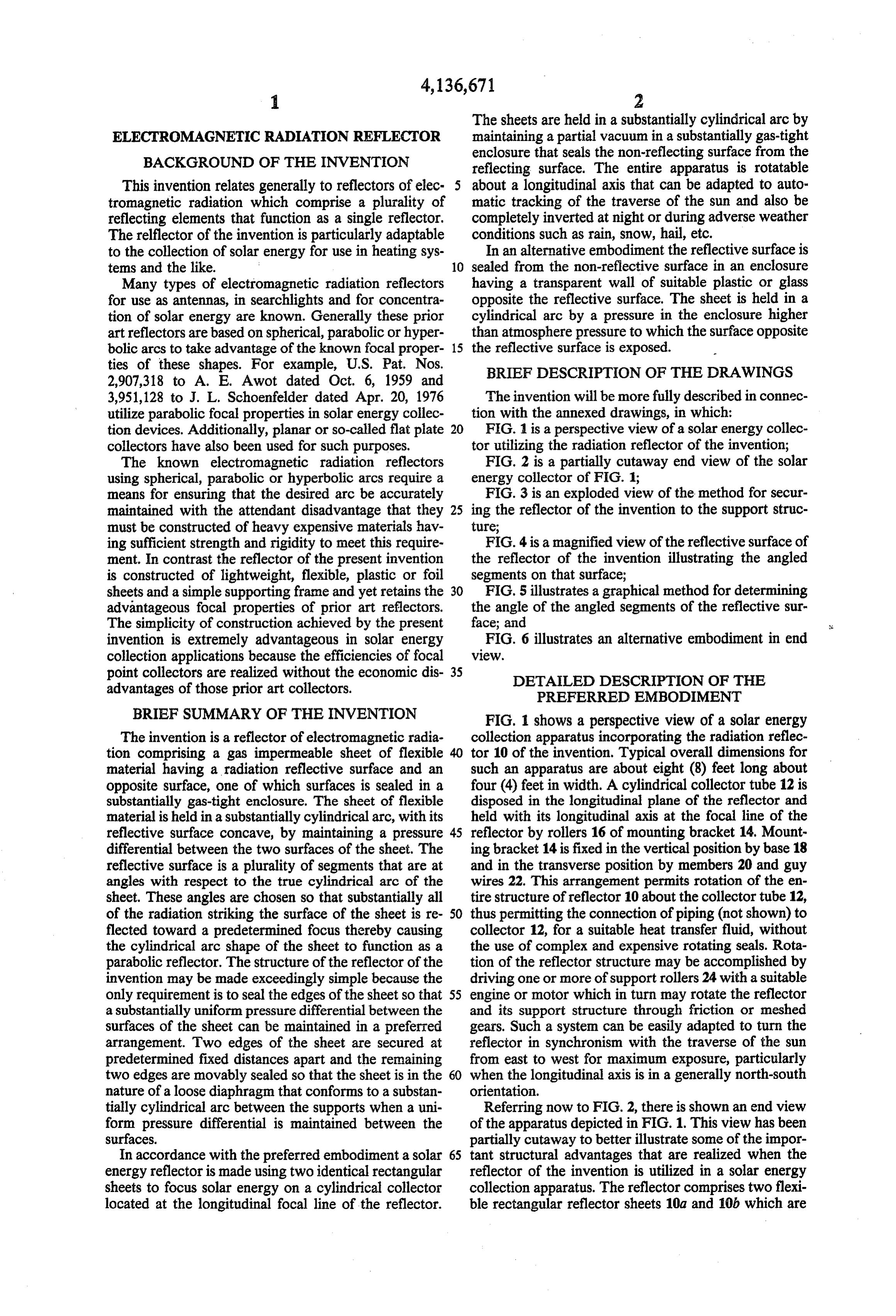
The sheets are held in a substantially cylindrical arc by
ELECTROMAGNETIC RADATION REFLECTOR maintaining a partial vacuum in a substantially gas-tight BACKGROUND OF THE INVENTION enclosure that seals the non-reflecting surface from the reflecting surface. The entire apparatus is rotatable
This invention relates generally to reflectors of elec 5 about a longitudinal axis that can be adapted to auto tromagnetic radiation which comprise a plurality of matic tracking of the traverse of the sun and also be reflecting elements that function as a single reflector. completely inverted at night or during adverse weather The relflector of the invention is particularly adaptable conditions such as rain, snow, hail, etc. to the collection of solar energy for use in heating sys In an alternative embodiment the reflective surface is tems and the like. 10 sealed from the non-reflective surface in an enclosure Many types of electromagnetic radiation reflectors having a transparent wall of suitable plastic or glass for use as antennas, in searchlights and for concentra opposite the reflective surface. The sheet is held in a tion of solar energy are known. Generally these prior cylindrical arc by a pressure in the enclosure higher art reflectors are based on spherical, parabolic or hyper than atmosphere pressure to which the surface opposite bolic arcs to take advantage of the known focal proper 15 the reflective surface is exposed.
ties of these shapes. For example, U.S. Pat. Nos. BRIEF DESCRIPTION OF THE DRAWINGS
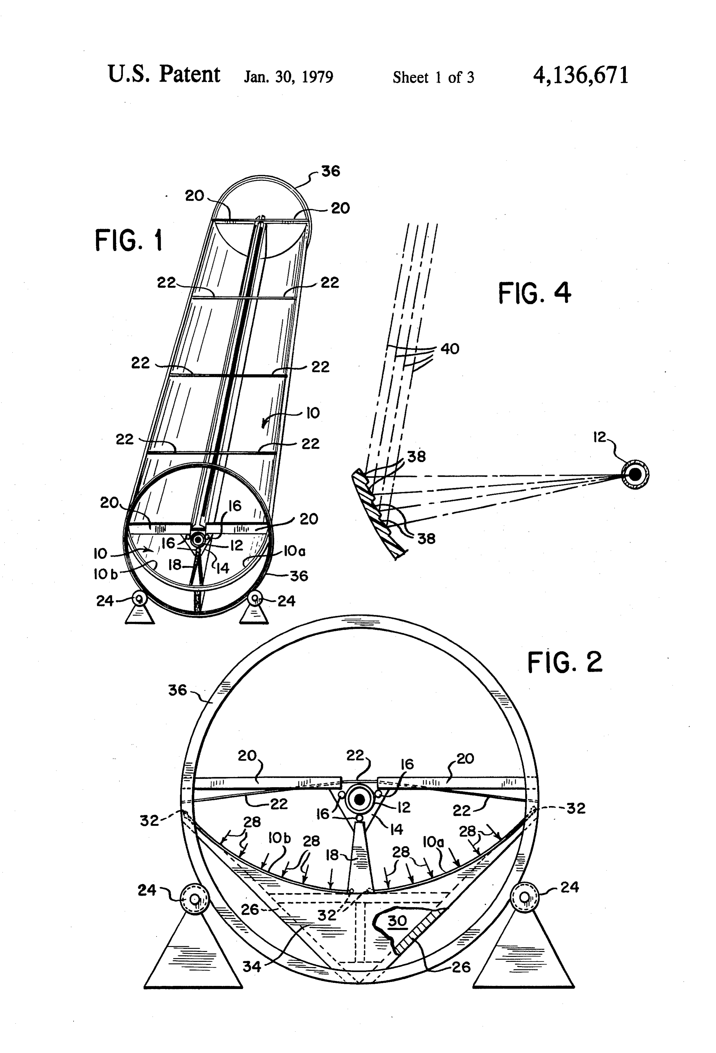
3,951,128 to J. L. Schoenfelder dated Apr. 20, 1976 The invention will be more fully described in connec utilize parabolic focal properties in solar energy collec tion with the annexed drawings, in which: tion devices. Additionally, planar or so-called flat plate 20 FIG. 1 is a perspective view of a solar energy collec collectors have also been used for such purposes. tor utilizing the radiation reflector of the invention; The known electromagnetic radiation reflectors FIG. 2 is a partially cutaway end view of the solar using spherical, parabolic or hyperbolic arcs require a energy collector of FIG. 1;
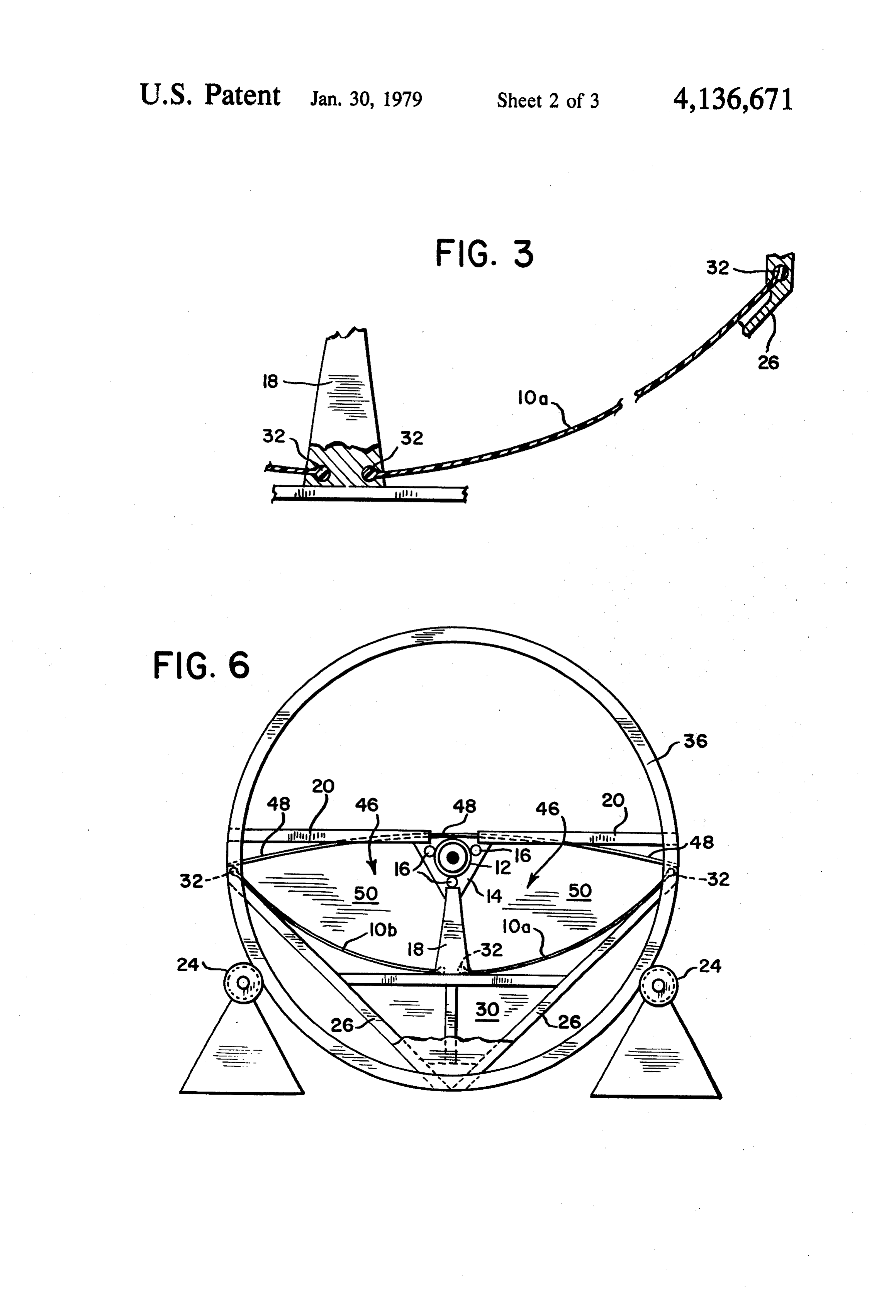
means for ensuring that the desired arc be accurately FIG. 3 is an exploded view of the method for secur maintained with the attendant disadvantage that they 25 ing the reflector of the invention to the support struc must be constructed of heavy expensive materials hav ture;
ing sufficient strength and rigidity to meet this require FIG. 4 is a magnified view of the reflective surface of ment. In contrast the reflector of the present invention the reflector of the invention illustrating the angled is constructed of lightweight, flexible, plastic or foil segments on that surface;
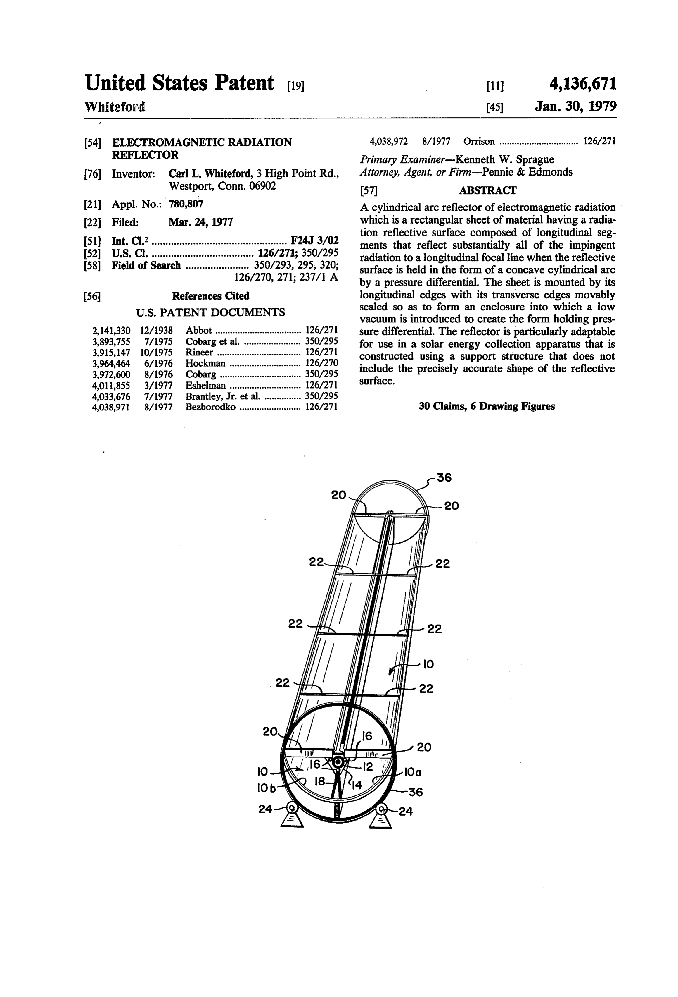
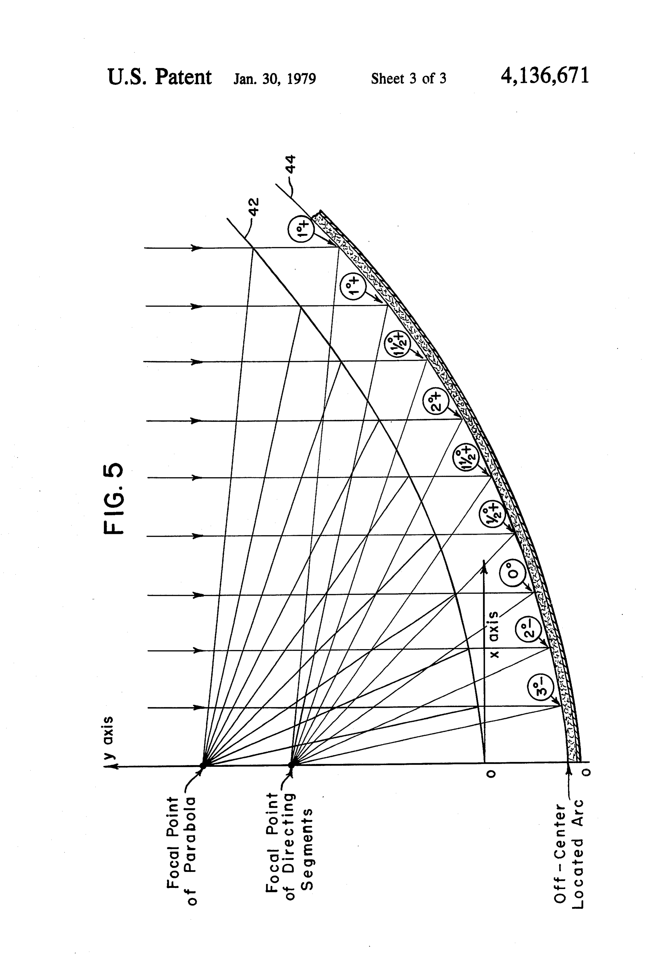
sheets and a simple supporting frame and yet retains the 30 FIG. 5 illustrates a graphical method for determining advantageous focal properties of prior art reflectors. the angle of the angled segments of the reflective sur The simplicity of construction achieved by the present face; and invention is extremely advantageous in solar energy FIG. 6 illustrates an alternative embodiment in end collection applications because the efficiencies of focal View, point collectors are realized without the economic dis 35 DETALED DESCRIPTION OF THE advantages of those prior art collectors. PREFERRED EMBODIMENT BRIEF SUMMARY OF THE INVENTION FIG. 1 shows a perspective view of a solar energy The invention is a reflector of electromagnetic radia collection apparatus incorporating the radiation reflec tion comprising a gas impermeable sheet of flexible 40 tor 10 of the invention. Typical overall dimensions for material having a radiation reflective surface and an such an apparatus are about eight (8) feet long about opposite surface, one of which surfaces is sealed in a four (4) feet in width. A cylindrical collector tube 12 is substantially gas-tight enclosure. The sheet of flexible disposed in the longitudinal plane of the reflector and material is held in a substantially cylindrical arc, with its held with its longitudinal axis at the focal line of the reflective surface concave, by maintaining a pressure 45 reflector by rollers 16 of mounting bracket 14. Mount differential between the two surfaces of the sheet. The ing bracket 14 is fixed in the vertical position by base 18 reflective surface is a plurality of segments that are at and in the transverse position by members 20 and guy angles with respect to the true cylindrical arc of the wires 22. This arrangement permits rotation of the en sheet. These angles are chosen so that substantially all tire structure of reflector 10 about the collector tube 12, of the radiation striking the surface of the sheet is re 50 thus permitting the connection of piping (not shown) to flected toward a predetermined focus thereby causing collector 12, for a suitable heat transfer fluid, without the cylindrical arc shape of the sheet to function as a the use of complex and expensive rotating seals. Rota parabolic reflector. The structure of the reflector of the tion of the reflector structure may be accomplished by invention may be made exceedingly simple because the driving one or more of support rollers 24 with a suitable only requirement is to seal the edges of the sheet so that 55 engine or motor which in turn may rotate the reflector a substantially uniform pressure differential between the and its support structure through friction or meshed surfaces of the sheet can be maintained in a preferred gears. Such a system can be easily adapted to turn the arrangement. Two edges of the sheet are secured at reflector in synchronism with the traverse of the sun predetermined fixed distances apart and the remaining from east to west for maximum exposure, particularly two edges are movably sealed so that the sheet is in the 60 when the longitudinal axis is in a generally north-south nature of a loose diaphragm that conforms to a substan orientation.
tially cylindrical arc between the supports when a uni Referring now to FIG. 2, there is shown an end view form pressure differential is maintained between the of the apparatus depicted in FIG.1. This view has been surfaces. partially cutaway to better illustrate some of the impor In accordance with the preferred embodiment a solar 65 tant structural advantages that are realized when the energy reflector is made using two identical rectangular reflector of the invention is utilized in a solar energy sheets to focus solar energy on a cylindrical collector collection apparatus. The reflector comprises two flexi located at the longitudinal focal line of the reflector. ble rectangular reflector sheets 10a and 10b which are
Page 6
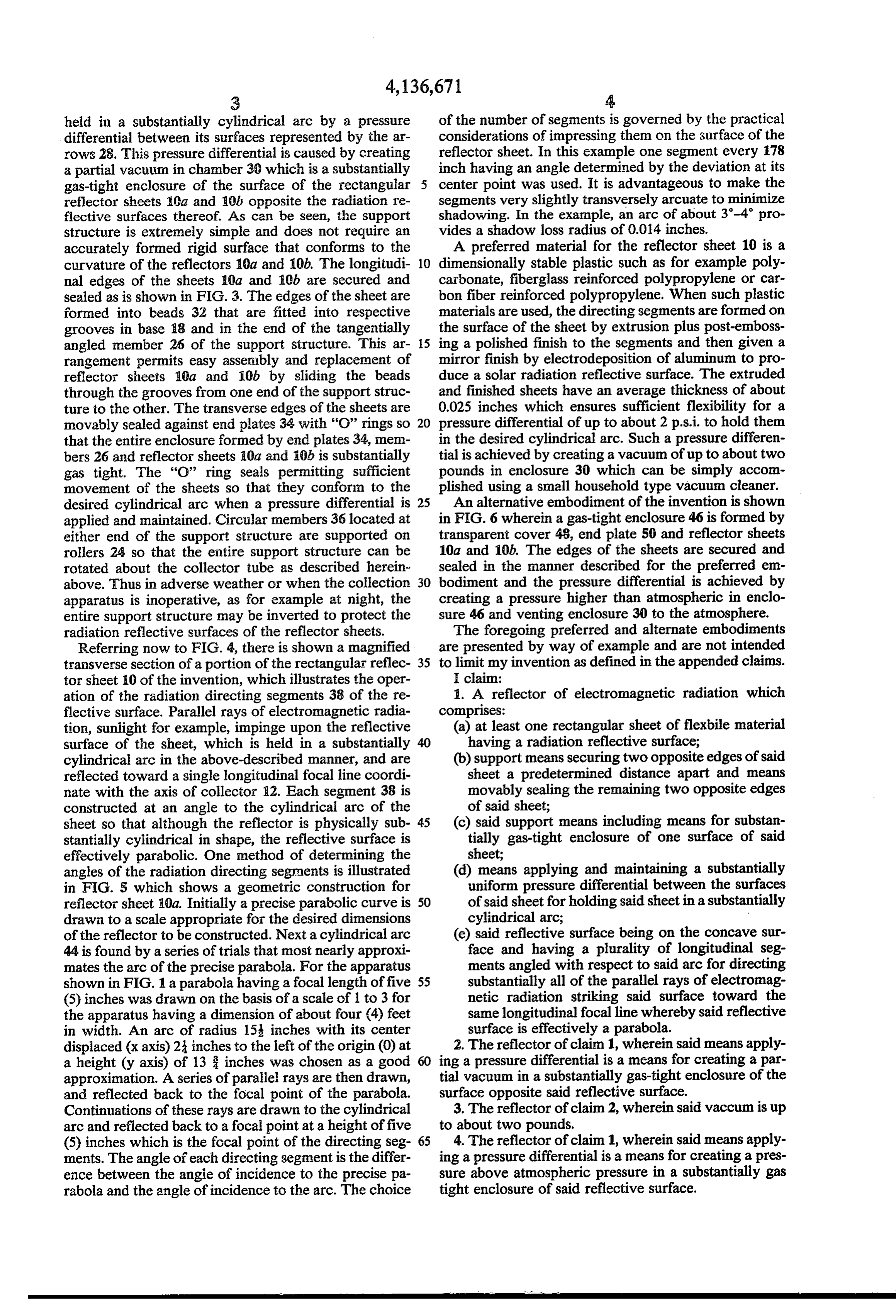
held in a substantially cylindrical arc by a pressure of the number of segments is governed by the practical differential between its surfaces represented by the ar considerations of impressing them on the surface of the rows 28. This pressure differential is caused by creating reflector sheet. In this example one segment every 178 a partial vacuum in chamber 30 which is a substantially inch having an angle determined by the deviation at its gas-tight enclosure of the surface of the rectangular 5 center point was used. It is advantageous to make the reflector sheets 10a and 10b opposite the radiation re segments very slightly transversely arcuate to minimize flective surfaces thereof. As can be seen, the support shadowing. In the example, an arc of about 3-4 pro structure is extremely simple and does not require an vides a shadow loss radius of 0.014 inches. accurately formed rigid surface that conforms to the A preferred material for the reflector sheet 10 is a curvature of the reflectors 10a and 10b. The longitudi 10 dimensionally stable plastic such as for example poly nal edges of the sheets 10a and 10b are secured and carbonate, fiberglass reinforced polypropylene or car sealed as is shown in FIG. 3. The edges of the sheet are bon fiber reinforced polypropylene. When such plastic formed into beads 32 that are fitted into respective materials are used, the directing segments are formed on grooves in base i8 and in the end of the tangentially the surface of the sheet by extrusion plus post-emboss angled member 26 of the support structure. This ar 15 ing a polished finish to the segments and then given a rangement permits easy assenably and replacement of mirror finish by electrodeposition of aluminum to pro reflector sheets 10a and iOb by sliding the beads duce a solar radiation reflective surface. The extruded through the grooves from one end of the support struc and finished sheets have an average thickness of about ture to the other. The transverse edges of the sheets are 0.025 inches which ensures sufficient flexibility for a movably sealed against end plates 34 with "O' rings so 20 pressure differential of up to about 2 p.s.i. to hold them that the entire enclosure formed by end plates 34, mem in the desired cylindrical arc. Such a pressure differen bers 26 and reflector sheets 0a and 10b is substantially tial is achieved by creating a vacuum of up to about two gas tight. The "O' ring seals permitting sufficient pounds in enclosure 30 which can be simply accom movement of the sheets so that they conform to the plished using a small household type vacuum cleaner. desired cylindrical arc when a pressure differential is 25 An alternative embodiment of the invention is shown applied and maintained. Circular members 36 located at in FIG. 6 wherein a gas-tight enclosure 46 is formed by either end of the support structure are supported on transparent cover 48, end plate 50 and reflector sheets rollers 24 so that the entire support structure can be 10a and 10b. The edges of the sheets are secured and rotated about the collector tube as described herein sealed in the manner described for the preferred em above. Thus in adverse weather or when the collection 30 bodiment and the pressure differential is achieved by apparatus is inoperative, as for example at night, the creating a pressure higher than atmospheric in enclo entire support structure may be inverted to protect the sure 46 and venting enclosure 30 to the atmosphere. radiation reflective surfaces of the reflector sheets. The foregoing preferred and alternate embodiments Referring now to FIG. 4, there is shown a magnified are presented by way of example and are not intended transverse section of a portion of the rectangular reflec 35 to limit my invention as defined in the appended claims. tor sheet 10 of the invention, which illustrates the oper I claim:
ation of the radiation directing segments 38 of the re 1. A reflector of electromagnetic radiation which flective surface. Parallel rays of electromagnetic radia comprises:
tion, sunlight for example, impinge upon the reflective (a) at least one rectangular sheet of flexbile material surface of the sheet, which is held in a substantially 40 having a radiation reflective surface; cylindrical arc in the above-described manner, and are (b) support means securing two opposite edges of said reflected toward a single longitudinal focal line coordi sheet a predetermined distance apart and means nate with the axis of collector 2. Each segment 38 is movably sealing the remaining two opposite edges constructed at an angle to the cylindrical arc of the of said sheet;
sheet so that although the reflector is physically sub 45 (c) said support means including means for substan stantially cylindrical in shape, the reflective surface is tially gas-tight enclosure of one surface of said effectively parabolic. One method of determining the sheet;
angles of the radiation directing segrinents is illustrated (d) means applying and maintaining a substantially in FIG. 5 which shows a geometric construction for uniform pressure differential between the surfaces reflector sheet 10a. Initially a precise parabolic curve is 50 of said sheet for holding said sheet in a substantially drawn to a scale appropriate for the desired dimensions cylindrical arc;
of the reflector to be constructed. Next a cylindrical arc (e) said reflective surface being on the concave sur 44 is found by a series of trials that most nearly approxi face and having a plurality of longitudinal seg mates the arc of the precise parabola. For the apparatus ments angled with respect to said arc for directing shown in FIG. 1 a parabola having a focal length of five 55 substantially all of the parallel rays of electromag (5) inches was drawn on the basis of a scale of 1 to 3 for netic radiation striking said surface toward the the apparatus having a dimension of about four (4) feet same longitudinal focal line whereby said reflective in width. An arc of radius 15 inches with its center surface is effectively a parabola. displaced (x axis) 23 inches to the left of the origin (0) at 2. The reflector of claim 1, wherein said means apply a height (y axis) of 13 inches was chosen as a good 60 ing a pressure differential is a means for creating a par approximation. A series of parallel rays are then drawn, tial vacuum in a substantially gas-tight enclosure of the and reflected back to the focal point of the parabola. surface opposite said reflective surface. Continuations of these rays are drawn to the cylindrical 3. The reflector of claim 2, wherein said vaccum is up arc and reflected back to a focal point at a height of five to about two pounds.
(5) inches which is the focal point of the directing seg 65 4. The reflector of claim 1, wherein said means apply ments. The angle of each directing segment is the differ ing a pressure differential is a means for creating a pres ence between the angle of incidence to the precise pa sure above atmospheric pressure in a substantially gas rabola and the angle of incidence to the arc. The choice tight enclosure of said reflective surface.
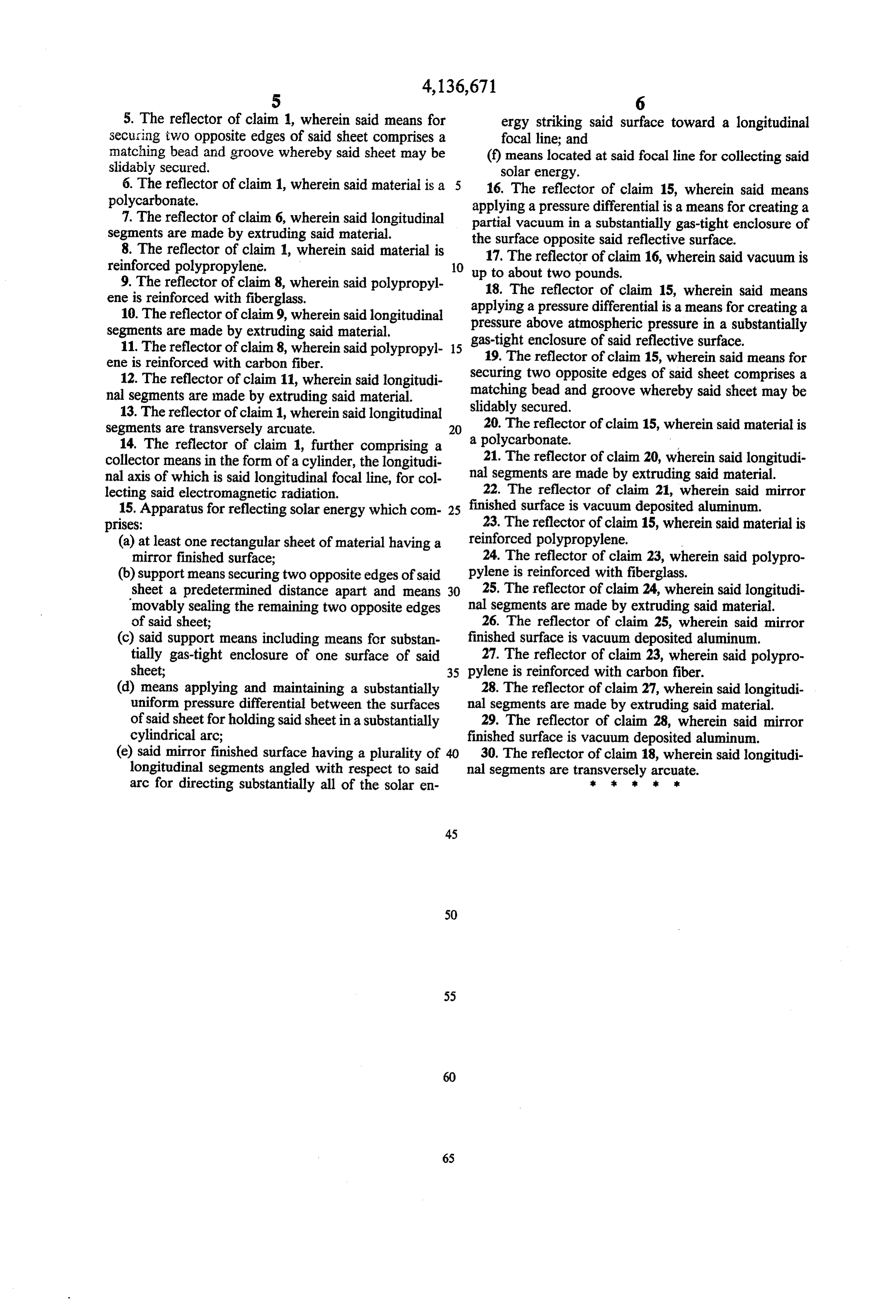
Page 7
5. The reflector of claim 1, wherein said means for ergy striking said surface toward a longitudinal securing two opposite edges of said sheet comprises a focal line; and matching bead and groove whereby said sheet may be (f) means located at said focal line for collecting said slidably secured. solar energy.
6. The reflector of claim 1, wherein said material is a 5 16. The reflector of claim 15, wherein said means polycarbonate. applying a pressure differential is a means for creating a 7. The reflector of claim 6, wherein said longitudinal partial vacuum in a substantially gas-tight enclosure of segments are made by extruding said material.
8. The reflector of claim 1, wherein said material is the17.surface The opposite said reflective surface.
reflector of claim 16, wherein said vacuum is reinforced polypropylene. 10 up to about two pounds.
9. The reflector of claim 8, wherein said polypropyl 18. The reflector of claim 15, wherein said means ene is reinforced with fiberglass. applying a pressure differential is a means for creating a 10. The reflector of claim 9, wherein said longitudinal pressure above atmospheric pressure in a substantially segments are made by extruding said material. gas-tight enclosure of said reflective surface. 11. The reflector of claim 8, wherein said polypropyl 15 19. The reflector of claim 15, wherein said means for ene is reinforced with carbon fiber.
12. The reflector of claim 11, wherein said longitudi matching securing two opposite edges of said sheet comprises a nal segments are made by extruding said material. bead and groove whereby said sheet may be 13. The reflector of claim 1, wherein said longitudinal slidably secured.
segments are transversely arcuate. 20 20. The reflector of claim 15, wherein said material is 14. The reflector of claim 1, further comprising a a polycarbonate.
collector means in the form of a cylinder, the longitudi 21. The reflector of claim 20, wherein said longitudi nal axis of which is said longitudinal focal line, for col nal segments are made by extruding said material. lecting said electromagnetic radiation. 22. The reflector of claim 21, wherein said mirror 15. Apparatus for reflecting solar energy which com 25 finished surface is vacuum deposited aluminum. prises: 23. The reflector of claim 15, wherein said material is (a) at least one rectangular sheet of material having a reinforced polypropylene.
mirror finished surface; 24. The reflector of claim 23, wherein said polypro (b) support means securing two opposite edges of said pylene is reinforced with fiberglass.
sheet a predetermined distance apart and means 30 25. The reflector of claim 24, wherein said longitudi movably sealing the remaining two opposite edges nal segments are made by extruding said material. of said sheet; 26. The reflector of claim 25, wherein said mirror (c) said support means including means for substan finished surface is vacuum deposited aluminum. tially gas-tight enclosure of one surface of said 27. The reflector of claim 23, wherein said polypro sheet; 35 pylene is reinforced with carbon fiber. (d) means applying and maintaining a substantially 28. The reflector of claim 27, wherein said longitudi uniform pressure differential between the surfaces nal segments are made by extruding said material. of said sheet for holding said sheet in a substantially 29. The reflector of claim 28, wherein said mirror cylindrical arc; finished surface is vacuum deposited aluminum. (e) said mirror finished surface having a plurality of 40 30. The reflector of claim 18, wherein said longitudi longitudinal segments angled with respect to said nal segments are transversely arcuate.
arc for directing substantially all of the solar en k . . k.
Page 8
UNITED STATES PATENT AND TRADEMARK OFFICE
CERTIFICATE OF CORRECTION
NVENTOR(S) : Carl L. Whiteford It is certified that error appears in the above-identified patent and that said Letters Patent are hereby corrected as shown below: Column 4, line 3 change "l78" to --l/2-- signed and Sealed this
Fifth Day of June 1979
Attesting officer Commissioner of Patents and Trademarks
Provenance
- Collection
- Cited prior art
- Original PDF
- patentimages.storage.googleapis.com →
- Filed
- 1977-03-24
- Pages
- 8
- Method
- pdftotext (the PDF's own text layer) + pdftoppm 300dpi page scans
- Source
- Google Patents bibliographic record
- Granted
- 1979-01-30
- Inventors
- Carl L. Whiteford
- Transcribed from
- patentimages.storage.googleapis.com →