patent · US4119086
Storage tank assembly
10 October 1978
Page 1 — bibliographic record
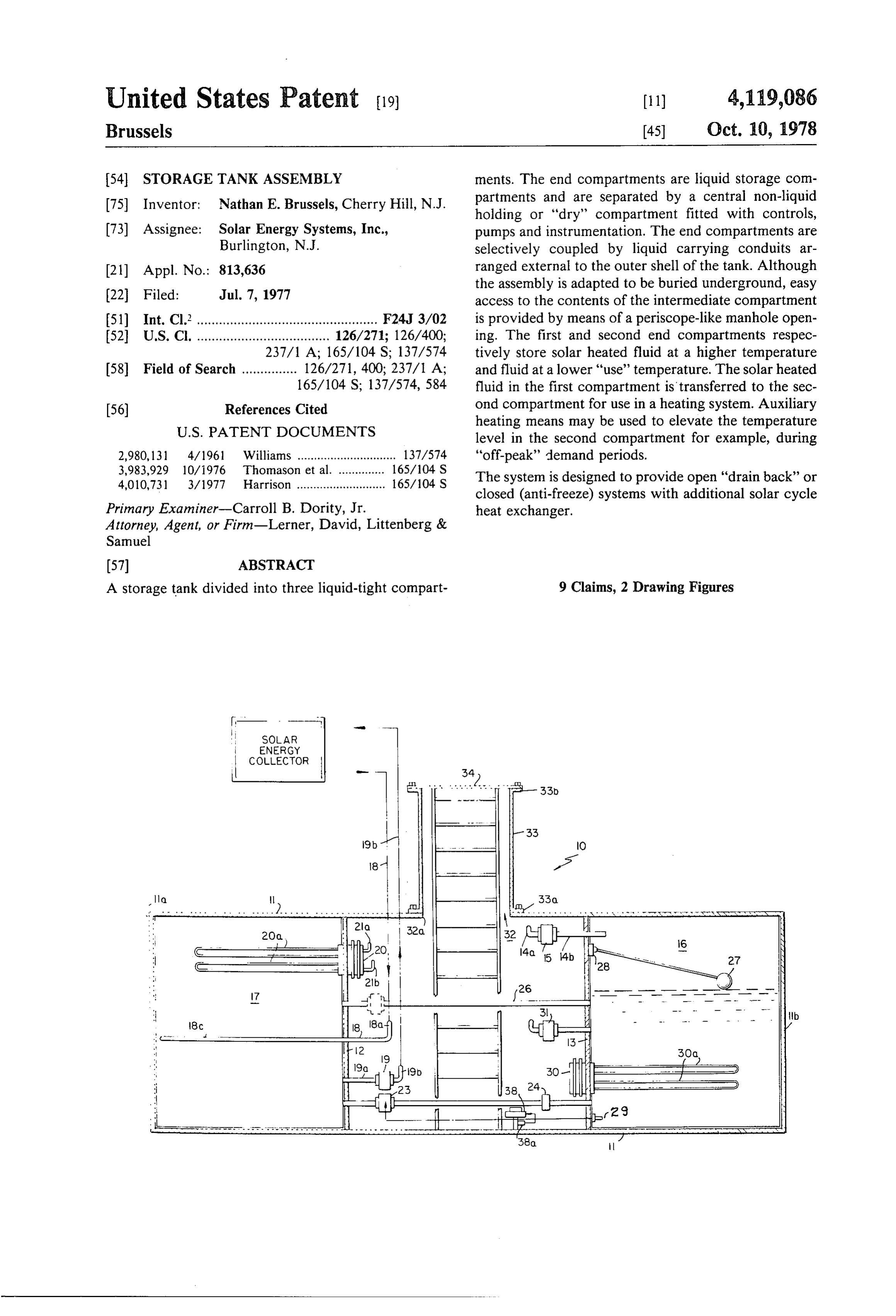
United States Patent (19) 11) 4,119,086 Brussels (45 Oct. 10, 1978 54). STORAGE TANK ASSEMBLY ments. The end compartments are liquid storage com 75) Inventor: Nathan E. Brussels, Cherry Hill, N.J. partments and are separated by a central non-liquid holding or "dry" compartment fitted with controls, 73) Assignee: Solar Energy Systems, Inc., pumps and instrumentation. The end compartments are Burlington, N.J. selectively coupled by liquid carrying conduits ar 21 Appl. No.: 813,636 ranged external to the outer shell of the tank. Although the assembly is adapted to be buried underground, easy 22 Filed: Jul. 7, 1977 access to the contents of the intermediate compartment (51) Int. Cl. ................................................. F24J 3/02 is provided by means of a periscope-like manhole open 52 U.S. Cl. .................................... 126/271; 126/400; ing. The first and second end compartments respec 237/1 A; 165/104 S; 137/574 tively store solar heated fluid at a higher temperature 58) Field of Search ............... 126/271, 400; 237/1 A; and fluid at a lower "use' temperature. The solar heated 165/104 S; 137/574, 584 fluid in the first compartment is transferred to the sec 56) References Cited ond compartment for use in a heating system. Auxiliary
heating means may be used to elevate the temperature level in the second compartment for example, during 2,980,131 4/1961 Williams .............................. 137/574 "off-peak' demand periods. 3,983,929 10/1976 Thomason et al. .............. 165/104 S The system is designed to provide open "drain back' or 4,010,731 3/1977 Harrison ........................... 165/104 S closed (anti-freeze) systems with additional solar cycle
Primary Examiner-Carroll B. Dority, Jr. heat exchanger.
Attorney, Agent, or Firm-Lerner, David, Littenberg &
Samuel
A storage tank divided into three liquid-tight compart 9 Claims, 2 Drawing Figures
SOLAR
ENERGY
COLLECTOR
Page 2
Drawing sheet — no readable text.
Page 3
Drawing sheet — no readable text.
Page 4
STORAGE TANK ASSEMBLY DETAILED DESCRIPTION OF THE
INVENTION
BACKGROUND OF THE INVENTION
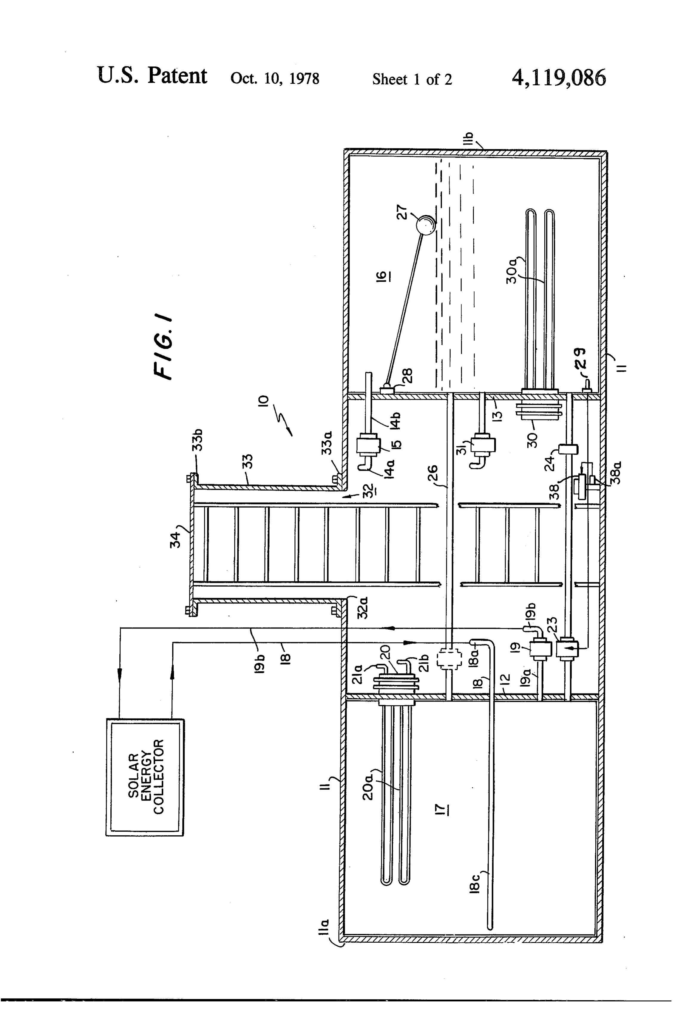
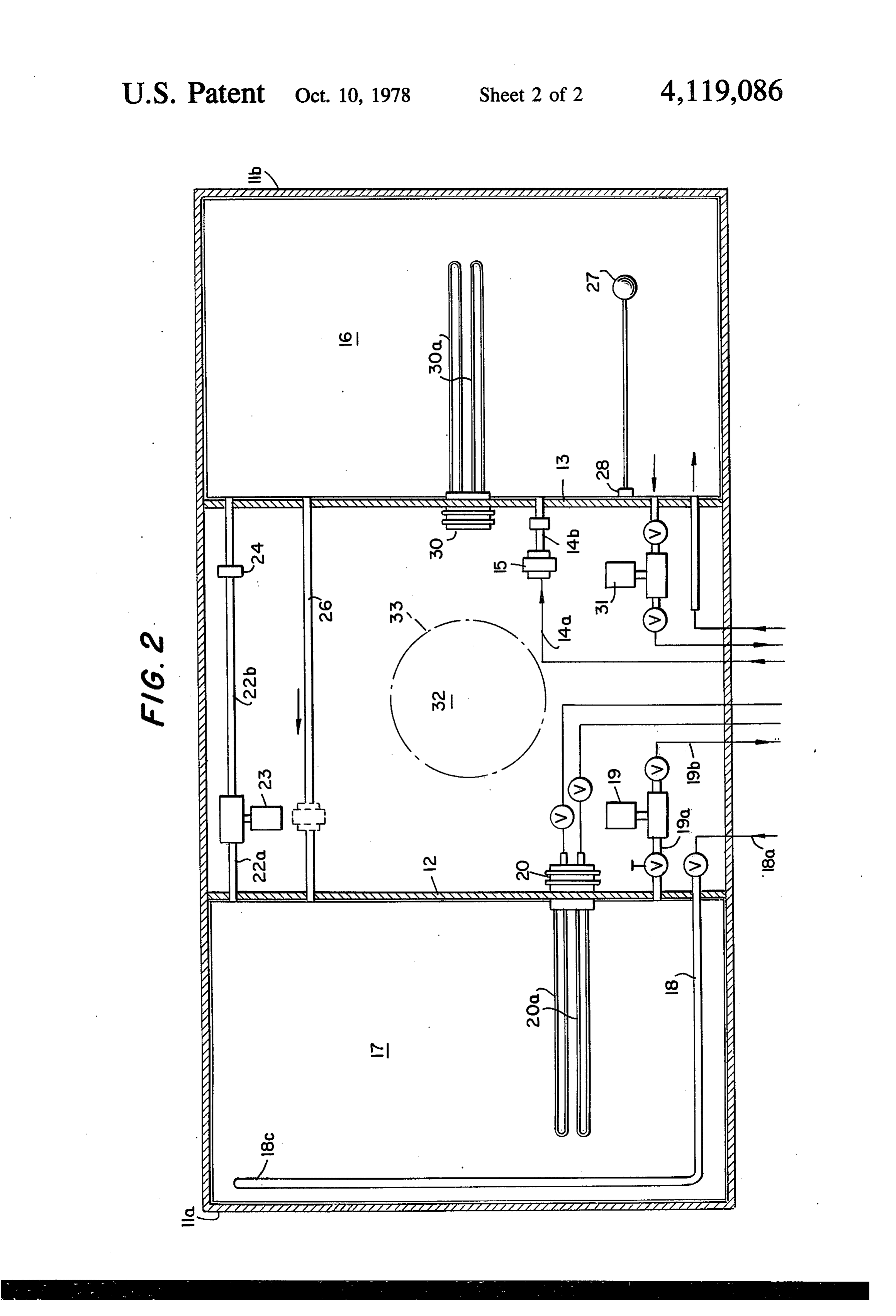
FIGS. 1 and 2 show apparatus 10 embodying the
Apparatus for storing heat energy are advanta- 5 principles of the present invention and comprising a geously employed in cooling and/or heating systems. steel tank 11, generally of a cylindrical shape and closed However, conventional apparatus lacks the capability by substantially flat end walls 11a and 11b. The interior of controlling fluid levels and temperature levels to is divided into three compartments by means of steel meet the demands of the particular application. plates 12 and 13 which serve as bulkheads and are O welded to the interior surface of tank 11 to form water
BRIEF DESCRIPTION OF THE INVENTION tight seals on the side of each plate. The right-hand The present invention is characterized by comprising compartment 16 is replenished with water from an ex a unitary tank structure capable of meeting the above ternal source (not shown) by means of a conduit 14a requirements, with a system design which lends itself to 15 which enters through the wall of the center compart ease of assembly, installation, maintenance and repair, ment and into water pump 15 which pumps the water and which provides a capability of storing heat energy into compartment 16 through conduit 14b and an open at the maximum level capable of being achieved by the ing in bulkhead 13. Pump 15 may be replaced by a solar collectors coupled to the first compartment and solenoid-operated valve.
transferring the hotter liquid when necessary to return 20 The left-hand compartment 17 receives heated fluid the temperature level of the liquid of the "use" tank to through conduit 18 which is coupled to a solar energy the desired "use' level. collector apparatus through its return conduit (not The unitary tank is divided into three fluid-tight com shown) to feed heated fluid into the left-hand end of partments defined by a pair of spaced partitioning walls compartment 17. The fluid is recirculated, after suitable welded to the interior surface of the tank. 25 mixing in compartment 17, to the solar collector appara The partitions keep the central compartment "dry" tus by means of an opening in bulkhead 12, conduit 19a, (i.e. free of fluid) in order to effectively serve as the pump 19 and conduit 19b which extends through an equipment housing compartment. Heated fluid is opening in the tank wall to the solar energy collector pumped into the solar fluid compartment from the solar supply conduit.
energy collector. 30 The solar energy collector apparatus may be of any A heater exchanger is utilized to transfer heat to a conventional design and the particular apparatus lends utilization means. no novelty to the present invention. The unit selected Transfer pumps are provided to assure equalization of may therefore be chosen to accommodate the applica liquid contents in the end compartments. The supple tion to best advantage. For example, collectors as de mental fluid compartment may be provided with means 35 scribed in U.S. application Ser. No. 815,499 filed July to equalize temperature levels and/or raise temperature signed 14, 1977 and Ser. No. 810,015 filed June 27, 1977 as levels by operation during "off-peak' demand periods employed to the assignee of the present application, may be in regions offering off-peak power at lower rates. The with the apparatus of the present invention. apparatus permits storage of solar heated liquid at the heat The solar collectors referred to hereinabove capture from solar radiation and transfer the heat to the highest temperature level the solar collectors are capa fluid flowing ble of achieving while the remaining liquid compart conduit 19b. Ittherethrough and derived from the supply should be understood that a conduit run ment serves as a source of withdrawing liquid at a de of a length sufficient to couple the solar collector sup sired "use" temperature, whereby the controls permit ply header, usually mounted liquid transfer to both replenish the liquid and to permit 45 to the conduit 19b is provided.well
above ground level, similar return conduit maintenance of the desired use temperature level. is also required. By extending the conduit 18c to the OBJECT AND BRIEF DESCRIPTION OF THE left-hand end of compartment 17, a better and more FIGURES uniform mixture of the liquid is obtained.
It is therefore a primary object to provide a novel 50 to Ifservice desired, a heat exchanger unit 20 may be provided a domestic hot water system.
unitary storage tank capable of storing fluid derived The unit is mounted upon bulkhead 12 and its coils from independent sources in separate liquid-tight com 20a extend through an opening in the bulkhead and into partments, whereby controls and fluid moving equip the liquid in compartment 17. Heat energy is withdrawn ment, which are housed in an intermediate compart and pumped through conduit 21a into the coils of a hot ment, are utilized to maintain the temperature and liquid 55 water tank (not shown) positioned at a remote location. level in the end "use" compartment at the desired level. The return from the coils is coupled to return conduit Another object of the present invention is to provide 21b and back to the heat exchanger coils 20a. apparatus of the type described hereinabove and which The compartment 17 is available to store the liquid is capable of providing simple access to the intermediate heated by the solar collector at the highest temperature compartment to facilitate maintenance and repair. level at which the solar collector is capable of achiev The above, as well as other objects, will become ing. Depending upon the size, type and number of solar apparent when reading the accompanying description collectors, the solar collectors may heat the liquid to a and drawings in which: level in the range from 100-200' F., for example, FIG. 1 shows a sectionalized elevational view of Since the temperatures required for heating applica storage apparatus designed in accordance with the prin 65 tions is typically in the range from 60-200 F., com ciples of the present invention; partment 16 serves as a storage medium for heating FIG. 2 is a schematic view showing the equipment applications (or other applications requiring liquid at and controls housed within the central compartment. temperature levels lower than that of compartment 17).
Page 5
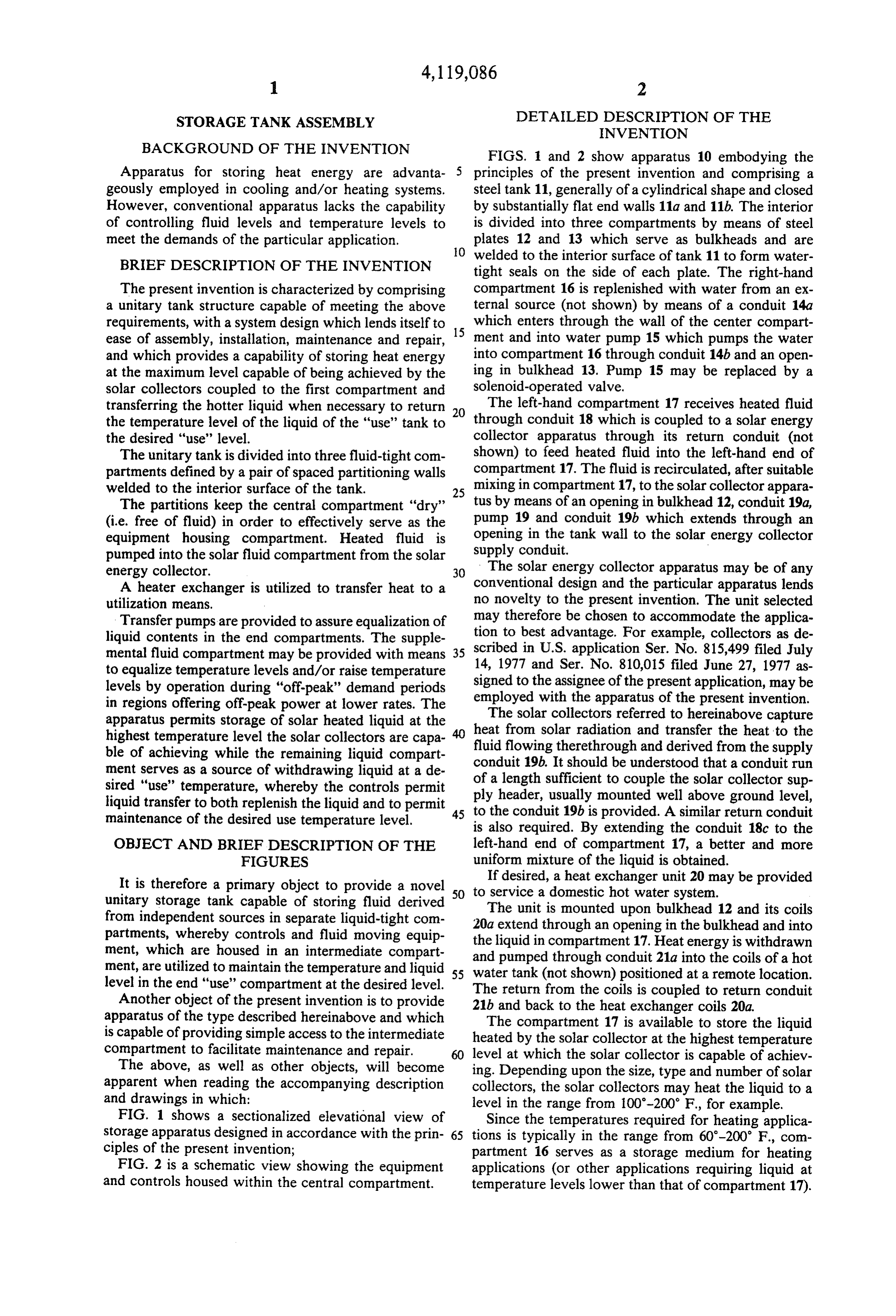
The transfer takes place by means of conduit 22a, dered operative in the event there is seepage of ground transfer pump 23 and conduit 22b which further in water into the "dry' compartment, in order to pump cludes a flow-preventer 24. When the temperature in the collected seepage out of the compartment. compartment 16 drops below a desired level, a tempera Many variations and modifications will now become ture sensor 29 activates pump 23 to transfer fluid from apparent to those skilled in the art. It is preferred there compartment 17 through conduit 22a, pump 23 and fore that the present invention be limited not by the conduit 22b, into compartment 16. Flow-preventer 24 specific disclosure herein but only by the appended automatically opens when pump 23 is activated to per claims.
mit fluid flow into compartment 16. When pump 23 is What is claimed is:
turned off, the flow-preventer closes and prevents flow 10 1. Apparatus for storing liquid at different tempera in the reverse direction. ture levels comprising unitary hollow tank means; The openings in the bulkheads 12 and 13 which com first and second bulkheads arranged in spaced apart municate with the conduits 22a and 22b are preferably fashion within the interior of the tank means and near the bottom of the tank. Conduit 26 serves as a being joined to the tank wall to form three water return conduit to accomodate water level equilization 15 tight compartments including first and second end and is preferably located just below the desired "full' compartments separated by a central compartment; capacity level of the compartments. first conduit means extending through said central The liquid level in compartment 16 is monitored by compartment for coupling said first compartment float member 27. When the liquid in compartment 16 to an external fluid heating source; drops below a desired level, float 27 moves down 20 second conduit means extending through said central wardly, tripping switch 28 mounted at bulkhead 13 compartment for coupling an external heated liquid which then activates pump 15 to replenish the contents utilization device to said second compartment; of compartment 16. Alternatively, pump 15 may be a third conduit means extending through said central valve when fluid can be gravity fed. compartment for transferring liquid between said Compartment 16 may be filled with an auxiliary 25 first and second compartments to regulate the tem heater 30 mounted upon bulkhead 13 and having heater perature levels of the liquids in said end compart coils extending into compartment 16. The auxiliary ments.
heater may be activated to maintain the desired level in 2. The apparatus of claim 1 wherein said external compartment 16, preferably during "off-peak' demand liquid heating means comprises solar energy collector periods in those regions which offer a cost reduction for 30 means, and external conduit means for coupling said power use during the off-peak demand periods. collector means to said first conduit means; The central compartment may also be fitted with a said first conduit means including pump means for pump 31 for pumping water to a heating coil or to a heat circulating liquid between said first compartment pump. and said collector means. The pump 31 may also be connected to closed circuit 35 3. The apparatus of claim 2 wherein said first conduit evaporator cooler for cooling the fluid in the closed means includes a conduit extension projecting through circuit system. the bulkhead common to said first and third compart In systems in which the heat exchanger to be cooled ments and to a position close to the end of the tank is cooler than the fluid in compartment 16 the pump remote from the last mentioned bulkhead to facilitate may be turned off to allow the liquid to drain back into uniform mixing of liquid in said first compartment. compartment 16 until the temperature level of the cool 4. The apparatus of claim 3 wherein said first conduit ant rises above the temperature in compartment 16. means comprises supply and return conduits coupled The tank is designed for installation at ground level between the tank wall and the first compartment, said or may be installed below ground. The latter installation supply conduit being coupled to said conduit extension; takes full advantage of the relatively constant tempera 45 said return conduit terminating at said common bulk ture level below the frost line thereby reducing the head.
temperature changes of stored liquid due to seasonal 5. The apparatus of claim 1 wherein said third conduit changes. To facilitate access for maintenance and/or means includes pump means for pumping fluid between repair the central compartment is provided with an said end compartments and through said third conduit opening 32 surrounded by a mounting flange 32a. A 50 CalS.
cylindrical turret extension 33 has a lower flange 33a 6. The apparatus of claim 1 wherein said conduit mating with flange 32a for securement by suitable fas means further comprises pump means for pumping liq tening means (not shown). An upper flange 33b sup uid in said second compartment to the liquid utilization ports a removable manhole cover 34 bolted or other SOCC.
wise fastened to flange 33b. Suitable gaskets (not 55 7. The apparatus of claim 1 further comprising liquid shown) are arranged between the mating flanges to level detection means mounted in said second compart provide water tight joinders. All connections to the end ment;
compartments to the central compartment to facilitate fourth conduit means extending through said cenral inspection and repair. A ladder 35 serves as the means to compartment for coupling said second compart gain access to the central compartment. The length of 60 ment to an external liquid source; turret extension 33 is selected to spring the upper end to valve means operated by said level detection means approximately surface level. For above-ground installa to open when the liquid level falls to permit liquid tions the shorter turret may be employed or the turret from the external source to enter said third com may be omitted by mounting the cover 34 directly upon partment.
flange 32a. The tank external surface is covered by an 65 8. The apparatus of claim 5 wherein said third conduit insulation such as urethane to reduce heat loss to the means comprises separate supply and return conduits atmosphere. The tank is furnished with a sump pump 38 extending between openings in said bulkheads which which includes an automatic switch 38a which is ren are located near the bottom of the tank;
Page 6
said return conduit extending between openings in ing in said tank wall communicating with said central compartment;
said bulkheads which are located at the level represent a hollow turret extension having its lower end joined ing full liquid capacity; to said opening and a removable cover being joined and said pump means being connected in said supply to its upper end to gain access to the central com conduit. partment from ground level while said tank is mounted belowxground level.
9. The apparatus of claim 1 further including an open sk k k x
Provenance
- Collection
- Cited prior art
- Original PDF
- patentimages.storage.googleapis.com →
- Filed
- 1977-07-07
- Pages
- 6
- Method
- pdftotext (the PDF's own text layer) + pdftoppm 300dpi page scans
- Source
- Google Patents bibliographic record
- Granted
- 1978-10-10
- Inventors
- Nathan E. Brussels; SOLAR ENERGY SYSTEMS Inc
- Transcribed from
- patentimages.storage.googleapis.com →