patent · US5496414
Stowable and deployable concentrator for solar cells
5 March 1996
Page 1 — bibliographic record
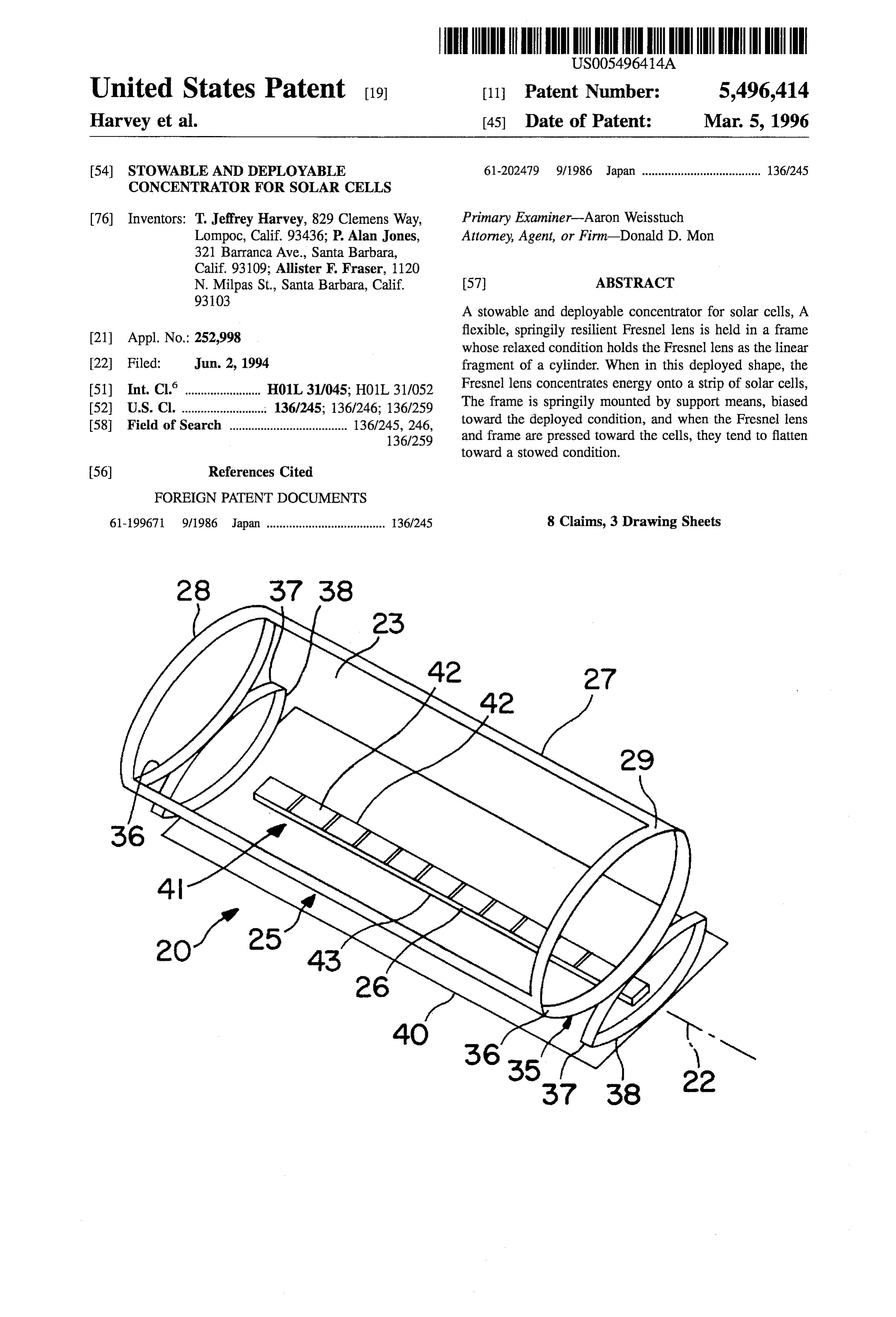
United States Patent (19) 11 Patent Number: 5,496,414 Harvey et al. (45) Date of Patent: Mar. 5, 1996 54). STOWABLE AND DEPLOYABLE 61-202479 9/1986 Japan ..................................... 136/245
CONCENTRATOR FOR SOLAR CELLS
76) Inventors: T. Jeffrey Harvey, 829 Clemens Way, Primary Examiner-Aaron Weisstuch Lompoc, Calif. 93436; P. Alan Jones, Attorney, Agent, or Firm-Donald D. Mon 321 Barranca Ave., Santa Barbara,
Calif. 93109; Allister F. Fraser, 1120
N. Milpas St., Santa Barbara, Calif. 57 ABSTRACT
9 A stowable and deployable concentrator for solar cells, A flexible, springily resilient Fresnel lens is held in a frame (21) Appl. No.: 252,998 whose relaxed condition holds the Fresnel lens as the linear 22 Filed: Jun. 2, 1994 fragment of a cylinder. When in this deployed shape, the 51) Int. Cl. ... HO1L 31/045. HOL 311052 Fresnel lens concentrates energy onto a strip of solar cells, 52 U.S. Cl. ............ sts. 1626,136,250. The frame is springily mounted by support means, biased 58 Field of search. ... 136245,246 toward the deployed condition, and when the Fresnel lens - -- - -- -- - - - - - - 136|259 and frame are pressed toward the cells, they tend to flatten toward a stowed condition.
FOREIGN PATENT DOCUMENTS
61-199671 9/1986 Japan ..................................... 136/245 8 Claims, 3 Drawing Sheets
Page 2
Drawing sheet — no readable text.
Page 3
Drawing sheet — no readable text.
Page 4
Drawing sheet — no readable text.
Page 5
STOWABLE AND DEPLOYABLE focal area for a linear lens will be linear, generally rectan CONCENTRATOR FOR SOLAR CELLS gular.
According to a preferred but optional feature of this
FIELD OF THE INVENTION invention, the lens is linear, trough-like, and flexible. The frame at the curved ends of the lens is also flexible. The
A concentrator for solar energy which focuses incident frame and the lens can be flattened when pressed toward the energy on a lesser cell area, which can be stowed in a lesser base, thereby optimally to reduce the volume of the con volume than its deployed volume, and which can readily be centrator in its stowed condition.
deployed to its deployed operative configuration from a According to yet another preferred but optional feature of stowed configuration. O the invention, the support means and the portions of the frame at the curved ends of the lens are formed as bent leaf
BACKGROUND OF THE INVENTION springs which tend to return to their deployed condition. Solar cells which convert radiant energy from the sun into According to yet another preferred but optional feature of electrical energy are used to power spacecraft such as 15 the invention, the substrate is foldable so as to compress the satellites. Designers of power systems for this application concentrators to their stowed configuration when folded together.
face numerous design constraints, of which weight is one of The above and other features of this invention will be the most critical. The extraordinarily high cost of placing a pound of weight into space is a serious constraint, and any fully understood from the following detailed description and improvement which can reduce the weight and still provide 20 the accompanying drawings, in which:
adequate performance is actively sought.
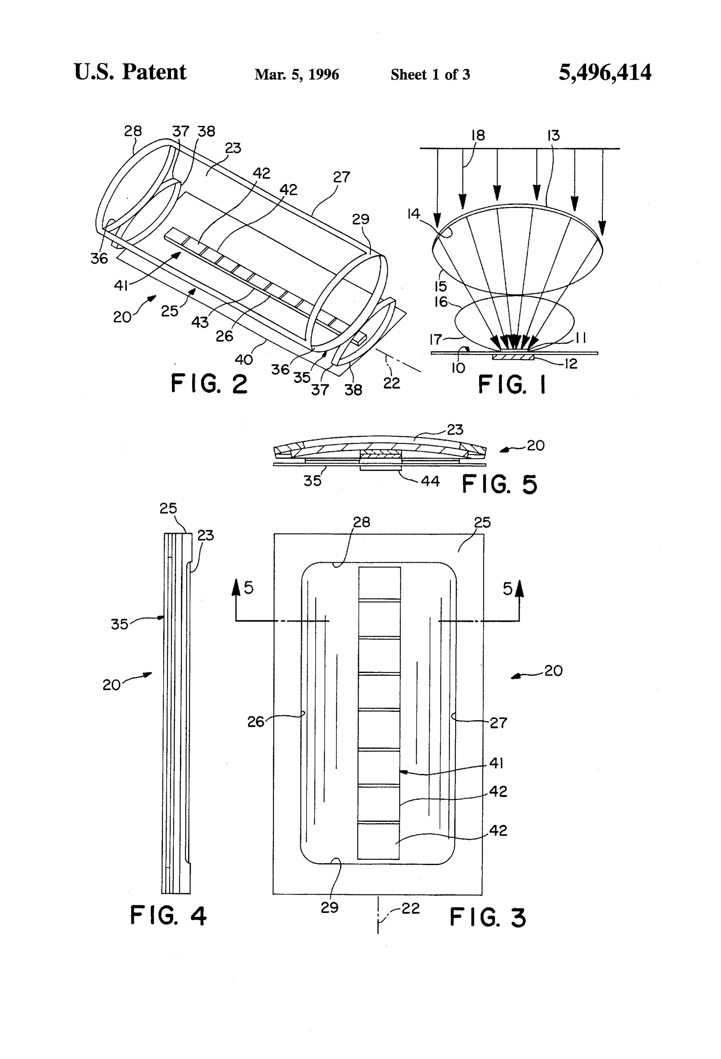
Another constraint is the need for shielding the solar cells BRIEF DESCRIPTION OF THE DRAWINGS against radiation in regions of high fluence. An example is FIG. 1 is an end view of a schematic showing of the found in Van Allen belt radiation at about 7,000 kilometers height, which is where many satellites orbit. It is riot 25 invention;
uncommon to apply a shielding layer of sufficient density to FIG. 2 is a perspective view of the presently-preferred an entire craft merely in order to protect some parts of it, embodiment of the invention;
such as the solar cells. This significantly increases the FIG. 3 is a top view of FIG. 2, showing the device in its weight of the craft. Any arrangement which can reduce the stowed condition;
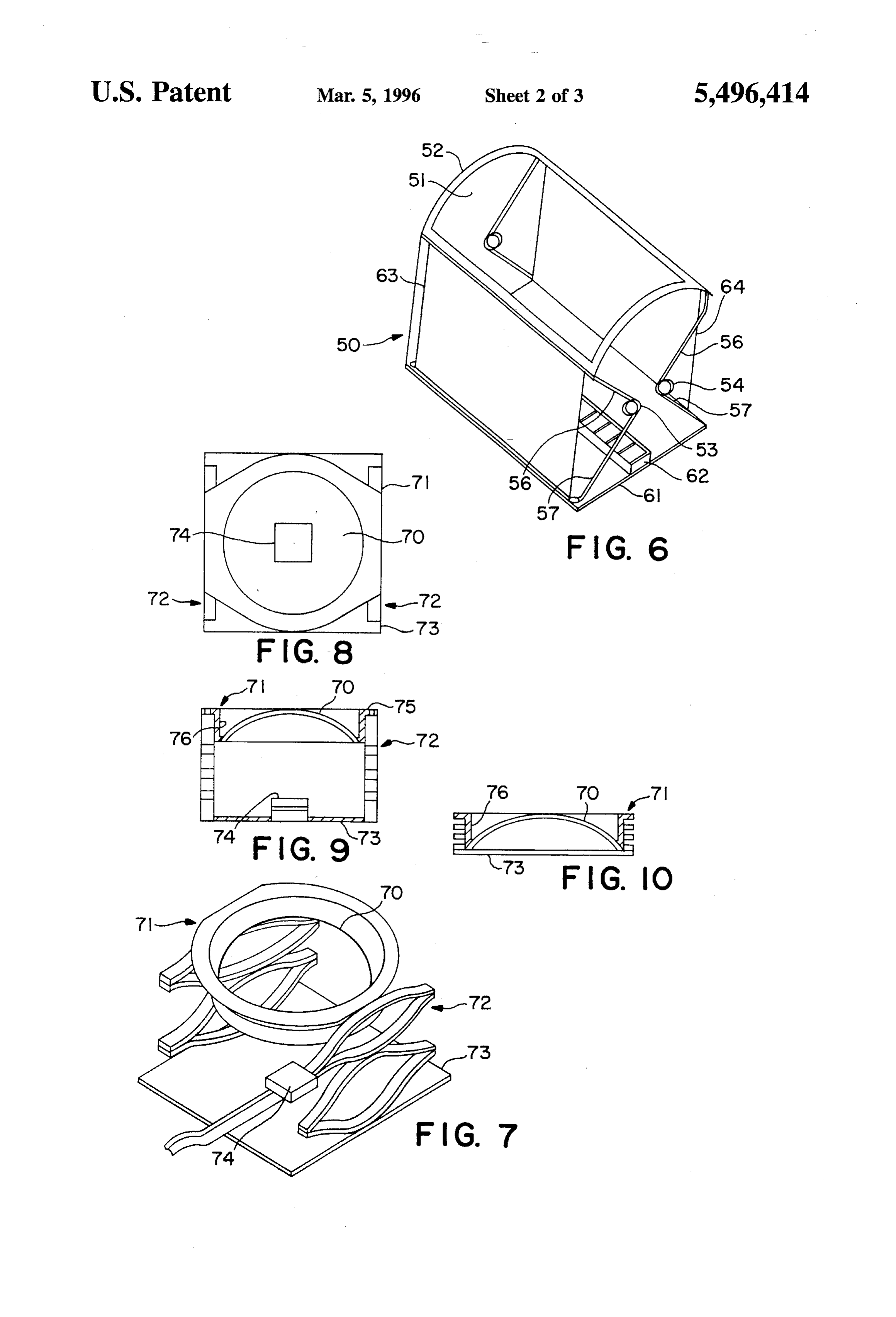
area or volume that must be shielded is also actively sought. FIG. 4 is a left hand side view of FIG.3; Yet another design constraint faced by the designer is the FIG. 5 is a cross-section taken at line 5-5 in FIG. 3; tendency of a concentrator-cell assembly to move out of FIG. 6 is a perspective view of another embodiment of the proper alignment when bonded to a substrate which has a invention;
significantly different thermal coefficient of expansion. 35 FIG. 7 is a perspective view of yet another embodiment Additionally, the mechanical fatigue caused by this move of the invention;
ment can degrade the system's lifetime.
Still another constraint is the volume required to pack a FIG. 8 is a top view of FIG.7;
solar cell array into the spacecraft for containment while FIG. 9 is an end view of FIG. 8 showing the device in its being launched. Reduction of stowed envelope volume is 40 deployed condition;
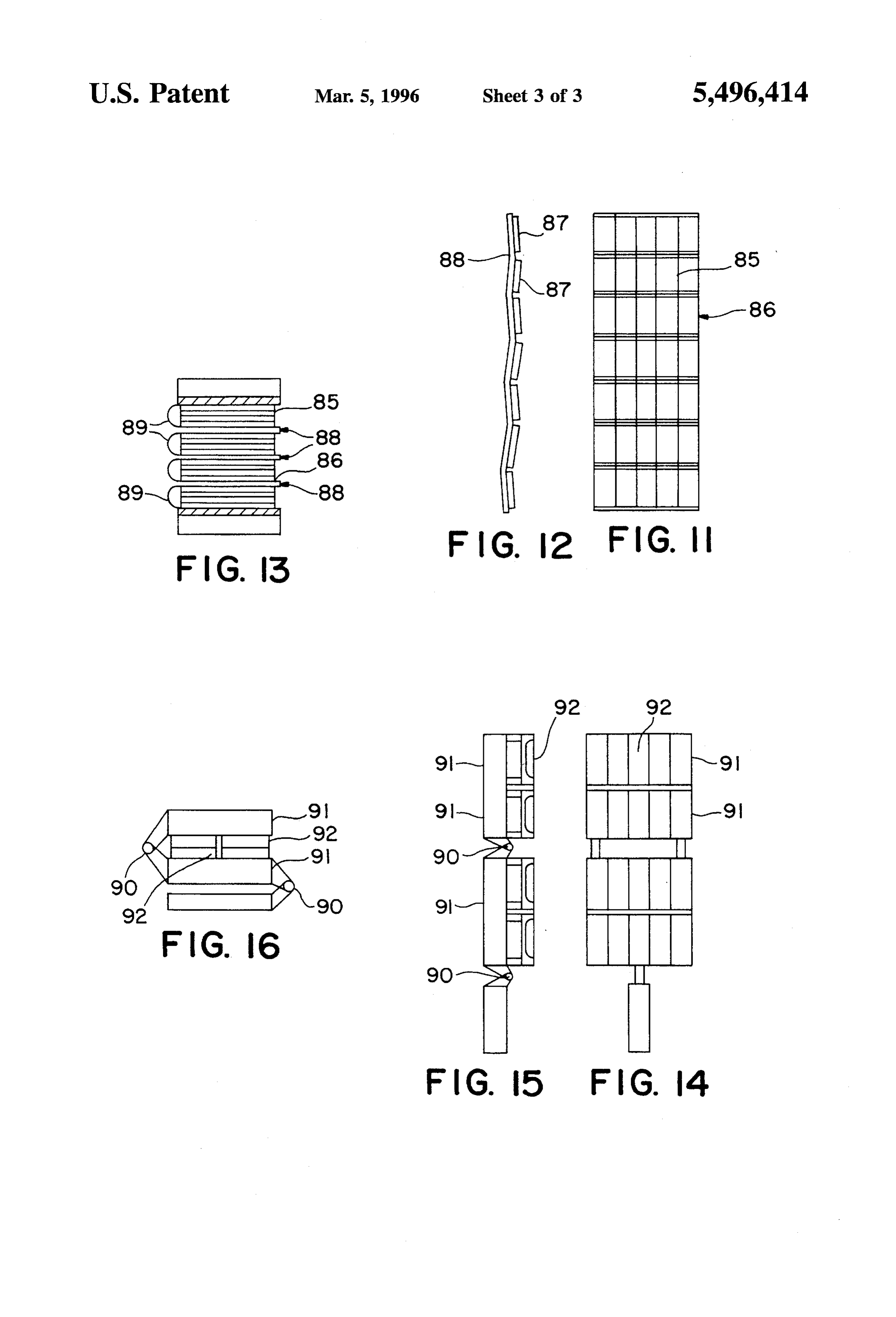
another design objective. FIG. 10 is a view similar to FIG.9 sectioned at the center This invention provides an improvement for all of the line, showing the device in its stowed condition; above design constraints. It requires only a lesser area of FIG. 11 is a plan view of a set of devices mounted to an cells for the same incident window area, and a configuration accordion foldable flexible substrate; stowable in a lesser volume and readily deployable to a 45 FIG. 12 is a left hand side view of FIG. 11; larger volume in which its elements are properly arranged. FIG. 3 is a side view of the embodiment of FIG. 11 in its The lesser cell area requires less shielding. The consequence stowed condition;
is a significant reduction of weight for the same kilowatt FIG. 14 is a plan view of a set of devices mounted to a output, and a reduction of weight needed for shielding. A rigid, hinged foldable substrate; further consequence is that the reduced area of cells can 50 reduce array costs. Also, the cells and their substrate can FIG. 15 is a left hand side view of FIG. 14; and have a close match of thermal coefficient of expansion so as FIG. 16 is a fragmentary side view of the embodiment of to eliminate movement of the cells out of alignment when FIG. 14 in its stowed condition. the cells and substrate are heated, as they will be.
55 DETAILED DESCRIPTION OF THE
BRIEF DESCRIPTION OF THE INVENTION INVENTION
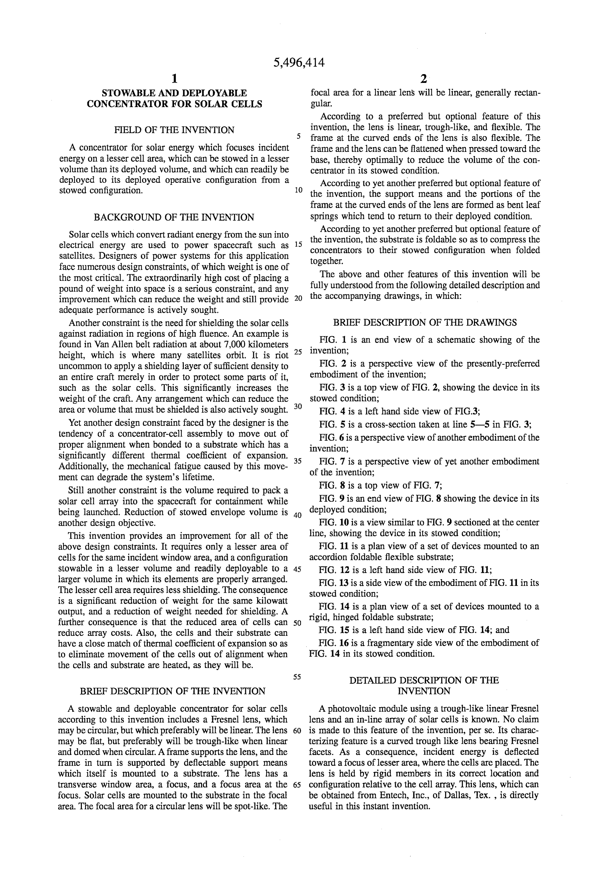
A stowable and deployable concentrator for solar cells A photovoltaic module using a trough-like linear Fresnel according to this invention includes a Fresnel lens, which lens and an in-line array of solar cells is known. No claim may be circular, but which preferably will be linear. The lens 60 is made to this feature of the invention, per se. Its charac may be flat, but preferably will be trough-like when linear terizing feature is a curved trough like lens bearing Fresnel and domed when circular. A frame supports the lens, and the facets. As a consequence, incident energy is deflected frame in turn is supported by deflectable support means toward a focus of lesser area, where the cells are placed. The which itself is mounted to a substrate. The lens has a lens is held by rigid members in its correct location and transverse window area, a focus, and a focus area at the 65 configuration relative to the cell array. This lens, which can focus. Solar cells are mounted to the substrate in the focal be obtained from Entech, Inc., of Dallas, Tex., is directly area. The focal area for a circular lens will be spot-like. The useful in this instant invention.
Page 6
In addition to linear lenses, conventional circular Fresnel 36,37.38. A similar construction is provided at both ends of lenses can be utilized, but these suffer from the fact that they the lens. These leaf springs in their undistorted condition are focus to a spot, and cannot enjoy the benefit of the elongated formed as shown in FIGS. 1 and 2, and tend to return to that linear lens and its linear, extended focal area. Linear lenses condition when released from compression. are to be preferred. The ends of leaf springs 36 are fixed to the ends 28 and The gist of this invention is schematically shown in FIG. 29 of the frame. The ends of leaf springs 37 and 38 are joined 1. A substrate 10 bears a sequence of solar cells 11, and to each other. The midpoints of leaf springs 36 and 37 are beneath the cells a radiation shield 12. A flexible trough-like joined to each other. The midpoint of leaf spring 38 is fixed Fresnel lens 13 is supported in its curved deployed condition to a substrate 40.
by a frame 14 and three leaf springs 15,16,17. The leaf 10 As best shown in FIGS. 1 and 3, a linear strip 41 of solar springs are joined at their ends. Leaf spring 15 is joined to cells 42 is mounted to the substrate, extending along the the frame. Springs 15 and 16 are joined at their mid points, focal area 43 of the lens. A sheet 44 of shielding material and spring 17 is joined to the substrate. The springs and (FIG. 5), such as copper, shields the cells from the bottom, frame are shown in their relaxed conditions, where they properly support the lens relative to the frame, and to 15 the cellattached being to the substrate. This is all the shielding for bottoms. The cell fronts are shielded traditionally relative to incident solar radiation 18. When it is to be with cover slide material.
stowed, the device is flattened (or nearly flattened) by The compressibility of the module is shown in FIG. 3. A applying a surface to it which is parallel to the substrate and flat element (not shown), or an element whose face has the forcing it toward the substrate. As will later be seen, the frame and springs are deflected to approach the substrate. 20 reverse against shape of the lens when compressed, is brought the lens, which flattens the lens, and compresses
When the flattening force is removed, the device will support means 35 in opposition to the inherent bias of the springly return to its illustrated deployed condition.
The presently-preferred embodiment of a concentrator 20 springs. The module will remain in the stowed condition until the compressive force is released. Then it inherently according to this invention is shown in FIGS. 2-5. The deployed condition is shown in FIG. 2. The stowed condi 25 returns to the illustrated deployed condition. In FIGS. 2-5 the inherent shape-memory of the support tion is shown in FIGS. 3-5. The concentrator has a linear axis 22. means is relied on to position the frame and the lens correctly. The lens is relatively forgiving, enabling an angu
A linear Fresnel lens 23 is formed as an inverted trough, lar misalignment around the central axis of as much as one extending axially. The lens is transparent to the wavelengths degree.
of interest. It bears characteristic Fresnel facets, extending 30 axially on its inner surface. The curvature of the outer FIG. 6 shows a variation 50 of the design in which an surface, and of the surface bearing the facets are designed identical Fresnel lens 51 and frame 52 are mounted to a pair such that the angles at which the light enters and exits the of wound coil springs 53.54 each with two arms 56,57. The lens are equal. This produces a condition that maximizes coils bias the arms apart, and tend to raise the frame relative optical efficiency while minimizing the effect of radial shape 35 to substrate 61. A solar cell array 62 is placed on the substrate in the focal area of the lens.
errors. An optical system which reduces the focused area to about /21 of the lateral array of the window of the lens is A pair of flexible restraints 63,64 are connected to respec readily attained. The details of the optical elements and their tive sides of the frame and to the substrate. They are flexible relative locations are not of importance to this invention. but inelastic. The springs can open only as far as the These can be calculated by any suitably skilled designer in 40 restraints permit, and thereby the restraints establish the the art. Instead, this invention relates to the support of this location of the sides of the lens above the substrate. system and enablement of its stowage. Despite the many advantages of a linear Fresnel lens, The advantages of this invention are best attained by there may be applications where a circular lens will be found providing the lens as a flexible member whose curvature in 45 to be preferable. Circular lenses (and also linear lenses) can deployment can be reduced or eliminated (flattened) in the be flat, but generally a curved lens will be preferred. While stowed condition. However, the use of rigid lenses, or of linear lenses readily deform toward a plane, circular domed lenses that can only partially be flattened, is within the scope lenses, are best left as domes. However, a springly flexible of this invention, domed lens, which can be deformed to a lesser height, is In FIG. 2, the lens is flexible, and is rectangular when 50 within the scope of this invention.
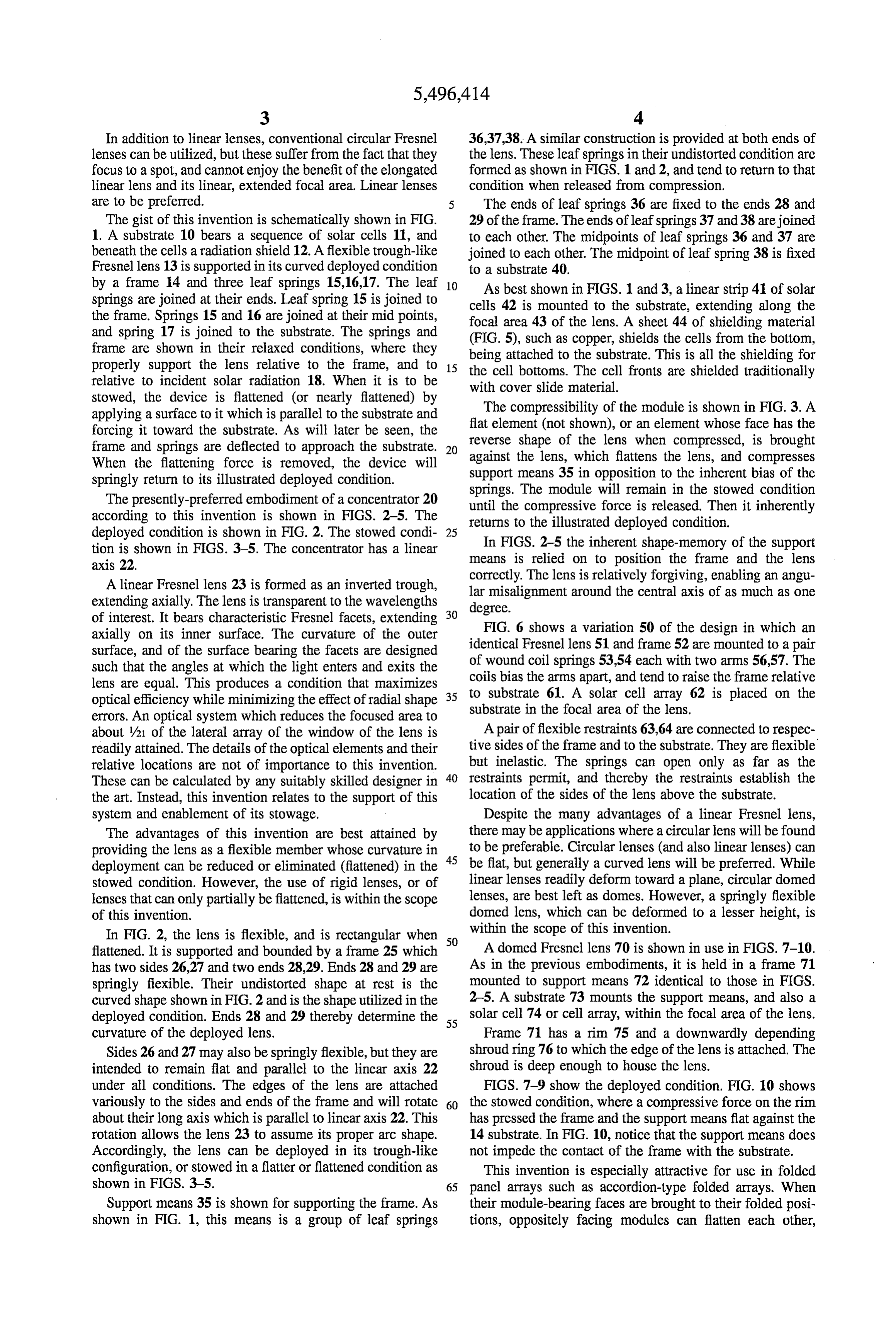
flattened. It is supported and bounded by a frame 25 which A domed Fresnel lens 70 is shown in use in FIGS. 7-10. has two sides 26.27 and two ends 28.29. Ends 28 and 29 are As in the previous embodiments, it is held in a frame 71 springly flexible. Their undistorted shape at rest is the mounted to support means 72 identical to those in FIGS. curved shape shown in FIG. 2 and is the shape utilized in the 2-5. A substrate 73 mounts the support means, and also a deployed condition. Ends 28 and 29 thereby determine the 55 solar cell 74 or cell array, within the focal area of the lens. curvature of the deployed lens. Frame 71 has a rim 75 and a downwardly depending Sides 26 and 27 may also be springly flexible, but they are shroud ring 76 to which the edge of the lens is attached. The intended to remain flat and parallel to the linear axis 22 shroud is deep enough to house the lens. under all conditions. The edges of the lens are attached FIGS. 7-9 show the deployed condition. FIG. 10 shows variously to the sides and ends of the frame and will rotate 60 the stowed condition, where a compressive force on the rim about their long axis which is parallel to linear axis 22. This has pressed the frame and the support means flat against the rotation allows the lens 23 to assume its proper arc shape. 14 substrate. In FIG. 10, notice that the support means does Accordingly, the lens can be deployed in its trough-like not impede the contact of the frame with the substrate. configuration, or stowed in a flatter or flattened condition as This invention is especially attractive for use in folded shown in FIGS. 3-5. 65 panel arrays such as accordion-type folded arrays. When Support means 35 is shown for supporting the frame. As their module-bearing faces are brought to their folded posi shown in FIG. 1, this means is a group of leaf springs tions, oppositely facing modules can flatten each other,
Page 7
S 6 thereby substantially decreasing the volume of the array in at least one solar cell mounted to said substrate in the its stowed condition, because the lesser stowed height focal area of said lens; and enables the panel faces to approach each other more closely deflectable support means mounted to said substrate and than if the modules had to retain their full operational height. connected to said frame, said support means being For example, FIGS. 11-13 show a module-bearing face resilient and inherently biased such as to exert a force 85 of an accordion-foldable panel array 86. Examples of in opposition between the substrate and the frame to modules 87 are shown on opposite sides of fold lines 88. tend to move the frame and the lens away from the When the array is folded, the modules will face each other, substrate to said deployed condition, and to be deflect and flatten each other to the extent required by the dimen able by a force exerted on said frame to overcome said bias and move said frame and said lens closer to said sions of the array. They will return to their deployed con 10 substrate in said stowed condition. dition when the array is unfolded. 2. A concentrator according to claim 1 in which said Notice in FIG. 13 that the spacing between modules must deflectable support means includes a plurality of leaf be sufficient to provide for a self-hinge 89 between the rows springs, two of said leaf springs being joined at their ends, of cells. This arrangement pertains when the substrate itself 15 the mid-point of one being fixed to said substrate, one is flexible. having its ends attached to the frame at the sides of said lens, Should the substrate be rigid, then as shown in FIGS. and two being joined at their mid-points. 14-16, hinges 90 will join adjacent substrates 91, so that 3. A concentrator according to claim 1 in which said cells 92 will properly abut each other in the stowed condition deflectable support means comprises a pair of springs which as shown in FIG. 16. include a central coil and a pair of arms biased apart by said 20 coil, said arms being attached to said frame to bias it away
Because the cells will be bonded to the substrate, too great from said substrate, and restraint means connected to said a difference between their thermal coefficients of expansion frame and to said substrate to limit the separation of the lens will cause curling of the substrate and tend to move the cells from the substrate.
out of angular alignment with the incident rays on it. This 4. A concentrator according to claim 1 in which the can significantly reduce the efficiency of the cells. Accord 25 thermal coefficient of expansion of the at least one solar cell ingly, the substrate should be selected so that its thermal and of the substrate are sufficiently close to one another that coefficient of expansion suitably approaches that of the cells. curvature of the substrate relative to the at least one solar cell Also, it is an advantage to provide a substrate which is not when they are both heated is insignificant. subject to degradation by radiation apt to be encountered, 5. A concentrator according to claim 1 in which said and which therefore does not require shielding. 30 substrate is inherently foldable in an accordion-like patter, a A suitable substrate for this purpose is shown in U.S. Pat. plurality of said lenses and support means being mounted to No. 5,298,085, issued to Harvey and Jones on Mar. 29, 1994. said substrate so as to abut each other when the substrate is This patentis incorporated herein by reference in its entirety folded.
for its showing of a substrate that can be used in all 6. A concentrator according to claim 1 in which said embodiments of this invention. 35 substrate comprises a plurality of rigid elements to which a As to the cells, silicon cells are useful, but GaAs/Ge cells, plurality of said solar cells and lenses are mounted, and in or tandem GaAs/GaSh cells have shown greater adaptability which hinges join adjacent ones of said elements, so that to incorporation into a line-focus array as required by this some of the said lenses abut one another when the substrate invention. All of these have a sufficiently close match of is folded.
thermal coefficient of expansion with the substrate disclosed 40 7. A stowable and deployable concentrator for solar cells, in said U.S. Pat. No. 5,298,085. comprising,
This invention thereby enables a very substantial reduc at least one flexible circular Fresnel lens, at least one said tion in weight of support structure and shielding required for lens being domed;
conventional modules. In fact it can be on the order of 50%, 45 a rigid frame supporting each of said at least one lens; a very important advantage to the spacecraft designer. a substrate;
This invention is not to be limited by the embodiments a solar cell mounted to said substrate in the focal area of shown in the drawings and described in the description, each of said at least one lens, and which are given by way of example and not of limitation, but deflectable support means mounted to said substrate and only in accordance with the scope of the appended claims. 50 connected to said frame, said support means being We claim:
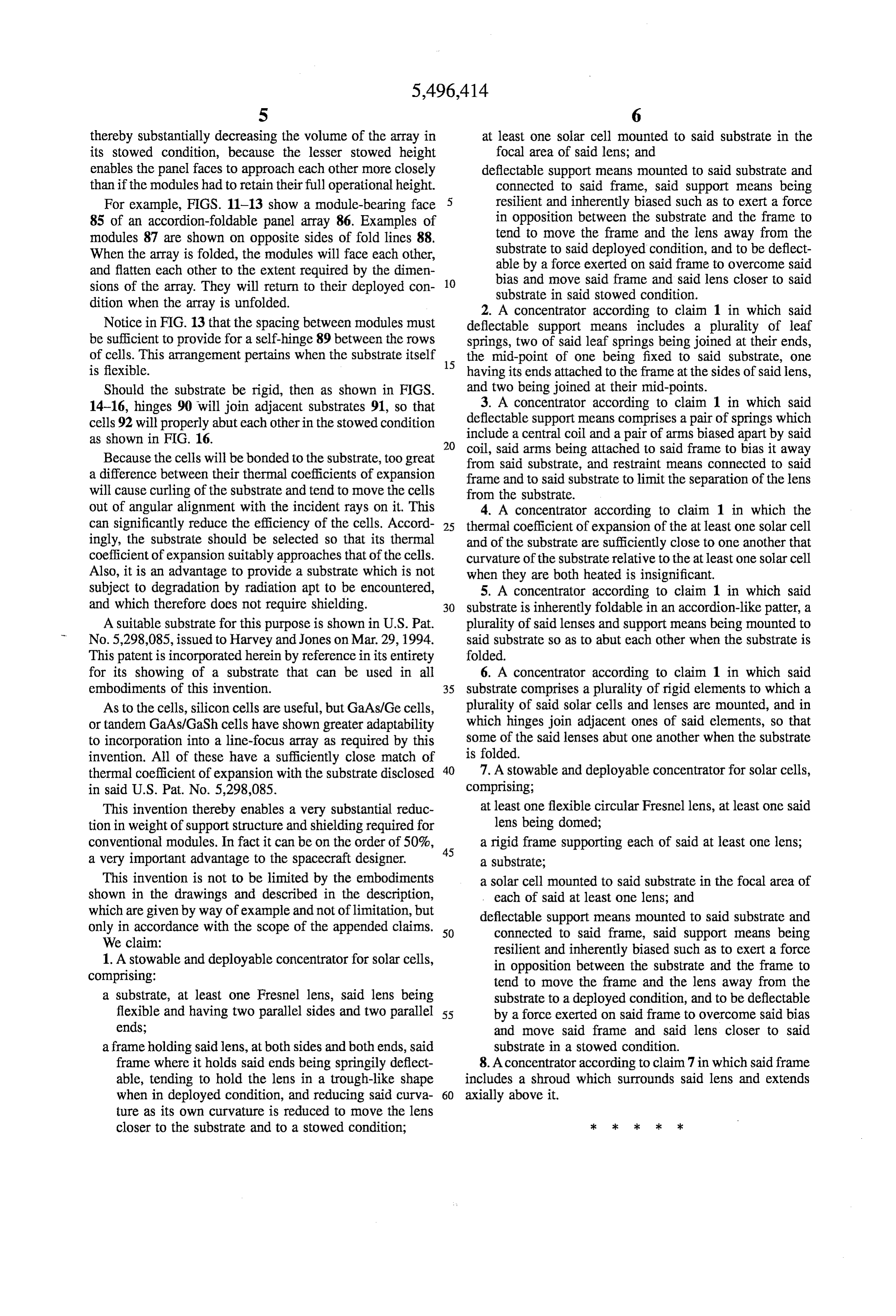
1. A stowable and deployable concentrator for solar cells, resilient and inherently biased such as to exert a force comprising: in opposition between the substrate and the frame to tend to move the frame and the lens away from the a substrate, at least one Fresnel lens, said lens being substrate to a deployed condition, and to be deflectable flexible and having two parallel sides and two parallel 55 by a force exerted on said frame to overcome said bias ends; and move said frame and said lens closer to said a frame holding said lens, at both sides and both ends, said substrate in a stowed condition.
frame where it holds said ends being springily deflect 8. A concentrator according to claim 7 in which said frame able, tending to hold the lens in a trough-like shape includes a shroud which surrounds said lens and extends when in deployed condition, and reducing said curva 60 axially above it.
ture as its own curvature is reduced to move the lens closer to the substrate and to a stowed condition;
Provenance
- Collection
- Cited prior art
- Original PDF
- patentimages.storage.googleapis.com →
- Filed
- 1994-06-02
- Pages
- 7
- Method
- pdftotext (the PDF's own text layer) + pdftoppm 300dpi page scans
- Source
- Google Patents bibliographic record
- Granted
- 1996-03-05
- Inventors
- T. Jeffrey Harvey; P. Alan Jones; Allister F. Fraser
- Transcribed from
- patentimages.storage.googleapis.com →