patent · US4040480
Storage of radioactive material
9 August 1977
Page 1 — bibliographic record
United States Patent (19) 11 4,040,480 Richards 45) Aug. 9, 1977
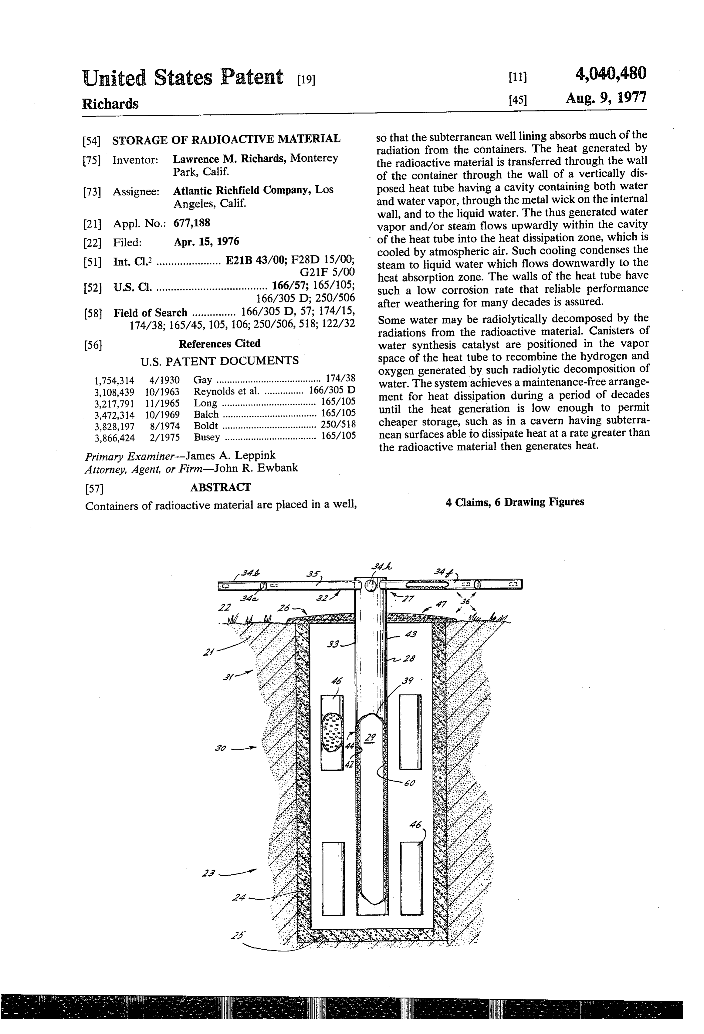
(54. STORAGE OF RADIOACTIVE MATERIAL so that the subterranean well lining absorbs much of the radiation from the containers. The heat generated by 75) Inventor: Lawrence M. Richards, Monterey the radioactive material is transferred through the wall Park, Calif. of the container through the wall of a vertically dis 73) Assignee: Atlantic Richfield Company, Los posed heat tube having a cavity containing both water Angeles, Calif. and water vapor, through the metal wick on the internal wall, and to the liquid water. The thus generated water 21 Appl. No.: 677,188 vapor and/or steam flows upwardly within the cavity (22 Filed: Apr. 15, 1976 of the heat tube into the heat dissipation zone, which is cooled by atmospheric air. Such cooling condenses the 51) Int. Cl. ...................... E21B 43/00; F28D 15/00; steam to liquid water which flows downwardly to the G21F 5/00 heat absorption zone. The walls of the heat tube have 52 U.S. C. ...................................... 166/57; 165/105; such a low corrosion rate that reliable performance 166/305 D; 250/506 after weathering for many decades is assured.
58 Field of Search ............... 166/305 D, 57; 174/15, Some water may be radiolytically decomposed by the 174/38; 165/45, 105, 106; 250/506, 518; 122/32 radiations from the radioactive material. Canisters of (56) References Cited water synthesis catalyst are positioned in the vapor
oxygen generated by such radiolytic decomposition of 1,754,314 4/1930 Gay ....................................... 174/38 water. The system achieves a maintenance-free arrange 3,108,439 10/1963 Reynolds et al. ............... 166/305 D ment for heat dissipation during a period of decades 3,217,791 11/1965 Long .................................... 165/105 until the heat generation is low enough to permit 3,472,314 10/1969 Balch .................................... 165/105 3,828, 197 8/1974 Boldt .................................... 250/518 cheaper storage, such as in a cavern having subterra 3,866,424 2/1975 Busey ................................... 165/105 nean surfaces able to dissipate heat at a rate greater than the radioactive material then generates heat.
Primary Examiner-James A. Leppink
Attorney, Agent, or Firm-John R. Ewbank
Containers of radioactive material are placed in a well, 4 Claims, 6 Drawing Figures
agazisz
Page 2
Drawing sheet — no readable text.
Page 3
Drawing sheet — no readable text.
Page 4
Drawing sheet — no readable text.
Page 5
STORAGE OF RADIOACTIVE MATERAL SUMMARY OF THE INVENTION
FIELD OF INVENTION
In accordance with the present invention, radioactive materials are packaged in containers and the containers
This invention relates to the long term storage of 5 are positioned in a subterranean zone in which a con depleted fuel or to fission products derived from repro tainer wall is in good heat transfer relationship with the cessing depleted fuel and/or other storage of radioac external wall of a heat tube extending into the storage tive materials for achieving dissipation of heat with well. The heat tube contains both water vapor and minimized problems related to the maintenance of the liquid water. At least in the lower heat absorption Zone, heat dissipation system. 10 and desirably in the upper heat dissipation zone, metal PRIOR ART means adjacent the metal walls of the heat tube signifi Long U.S. Pat. No. 3,217,791 employs a vertical heat means increases cantly the heat transfer surface. Such metal tube to transfer arctic atmospheric coldness to maintain plurality of layers of aswire is designated a wick and may consist of a mesh, or sintered open cell the frozen condition of permafrost. 15 porous metal, or other heat conductive high surface
Balch U.S. Pat. No. 3,472,314 employs a vertical tube area structure increasing the area permitting equilibria having internal conduits and baffles adapted to circulate between water vapor and flowable film of liquid water. a liquid by thermosiphon action between the upper Zone in which heat is radiated to a cold atmosphere and a The present invention concerns the transfer of radioac subterranean zone in which heat is absorbed to keep the 20 tive heat from a subterranean well to the atmosphere by subterranean zone almost as cold as the atmosphere. use of a heat tube, and is intended to embrace generi The tube features relatively thin metal because the heat cally future improvements in heat tubes. The heat gen transfer is not dependent upon vaporization and con erated by the radioactive material flows through the densation cycles and/or other potentiality of high pres wall of its container and through the wall of the heat sure. Explosion hazards attributable to local weakening 25 tube into the wick water, generating water vapor or of the tube are also minimized by filling substantially all steam from the water film on the wick. The steam flows of the tube with a liquid boiling far above the contem into the heat dissipation zone of the cavity of the heat plated temperature of the warm zone. tube where the water vapor is condensed as the upper Gay, U.S. Pat. No. 1,754,314 employs a pump to arms of the heat tube are cooled by the atmosphere. circulate oil between subterranean electrical cables and 30 Desirably, wick aids condensation of the steam. It is a heat exchanger. Boiling methanol is refluxed, using possible to expose a large area of the heat tube to the the coolness of the atmosphere to condense the metha atmosphere, so that whether a wick is employed in the nol in vertical tubes, thereby cooling the oil in said heat heat dissipation zone may depend in part upon the rela exchanger.
Busey, U.S. Pat. No. 3,866,424 employs capsules of 35 tive cost of additional tube surface and the cost of wick structures. During a period of storage of several de radioactive waste to heat liquid sodium and a heat ex cades, the amount of heat generated by the radioactive changer to generate steam of operate a turbine. In the material can vary and the atmospheric conditions relat event of failure of the liquid sodium coolant system, the ing to wind velocity, precipitation, and temperature can capsules may fall onto shock absorbers at the bottom of vertical tubes immersed in a pool which is a part of 40 vary. Such variations in heat absorption and/or heat standby coolant system. A pressurized gas minimizes dissipation affect the rates of circulation of liquid water evaporation of the liquid in the tubes under normal and steam within the cavity. The heat tube functions conditions but if other coolant systems fail, such tube automatically throughout the range of gas velocities liquid is evaporated and the vapors are cooled in a and range of gas pressures for which such heat tube was higher portion of the tube, some of which is surrounded 45 designed.
by a pool of an emergency cooling system, and some of Radiolytic decomposition of water prompts a mixture which radiates heat to the atmosphere. of hydrogen and oxygen to flow into the vapor space of Boldt, U.S. Pat. No. 3,828, 197 recommends that a the cavity of the heat tube, where such mixture contacts container about 1 foot in diameter and 10 feet long be a water synthesis catalyst, thereby being converted placed in a cast steel cask having 16 inch walls (about 45 50 back to water vapor. Such water synthesis catalyst inch diameter by 13 feet long) for storage of radioactive prevents the build-up of excessive pressure within the wastes for several decades until the heat dissipation cavity.
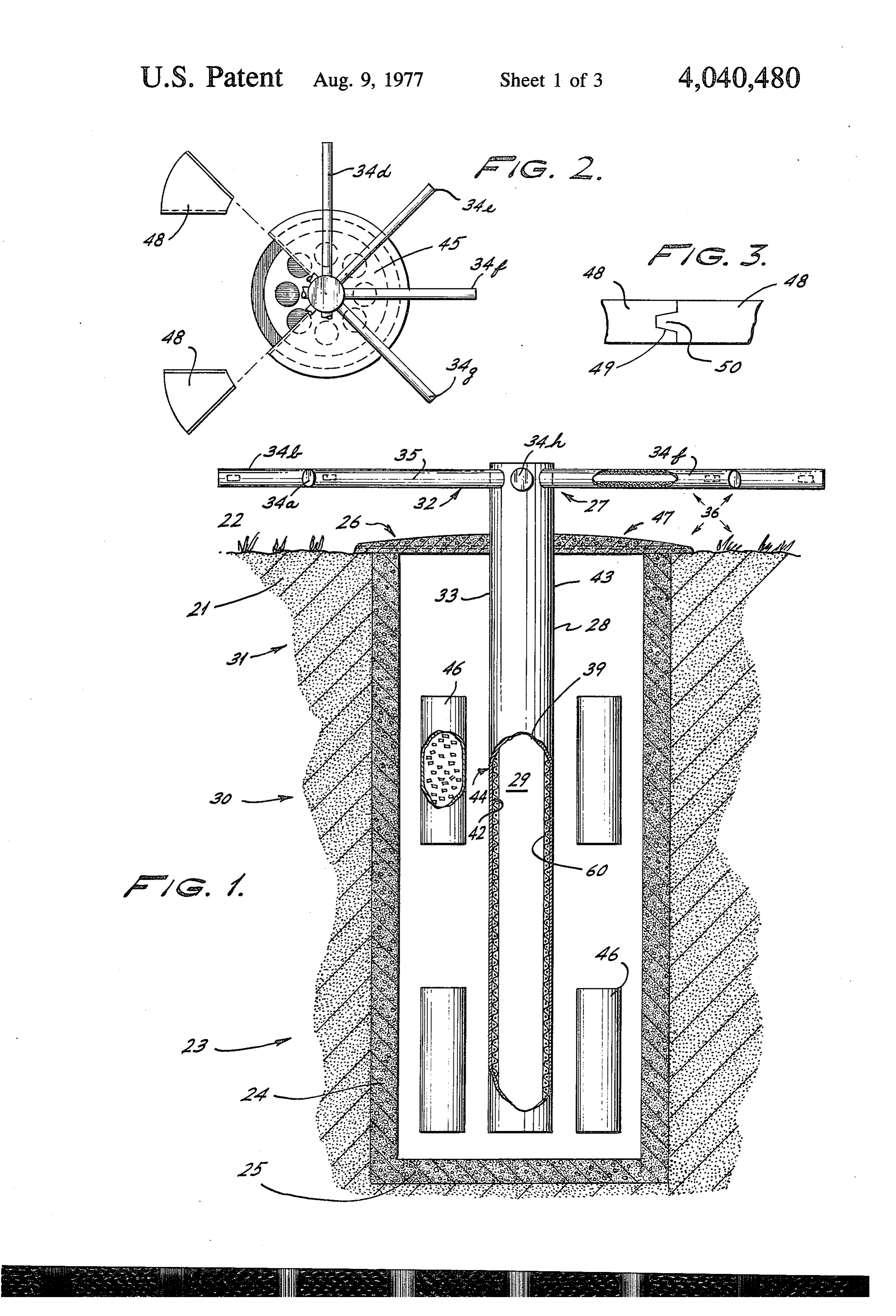
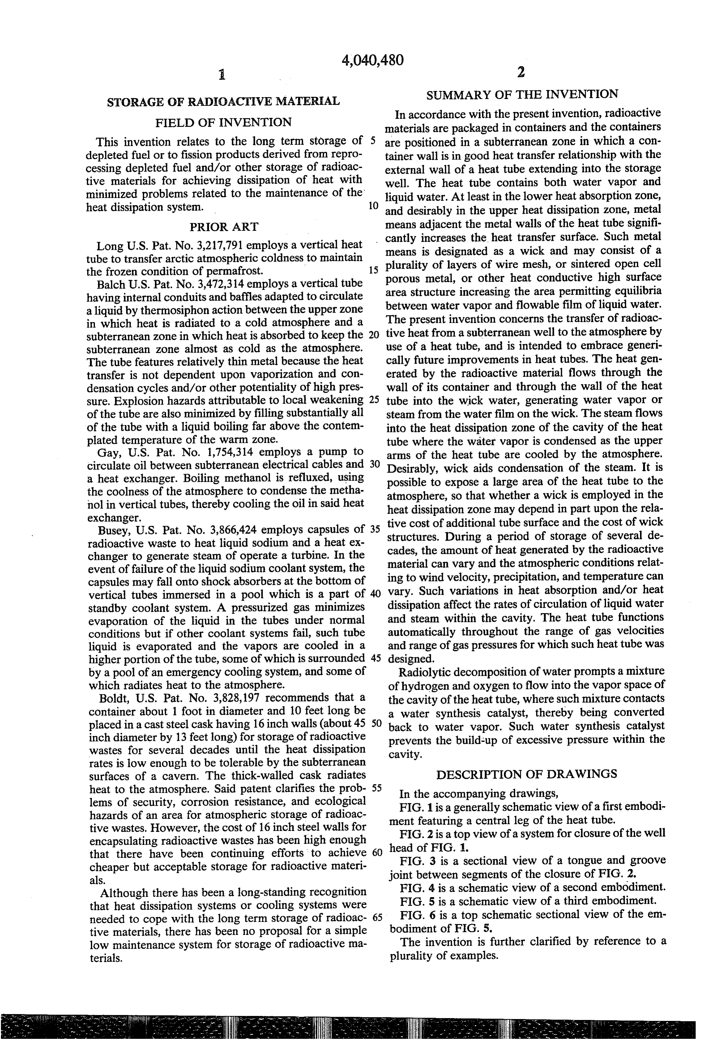
rates is low enough to be tolerable by the subterranean surfaces of a cavern. The thick-walled cask radiates DESCRIPTION OF DRAWINGS heat to the atmosphere. Said patent clarifies the prob 55 In the accompanying drawings, lems of security, corrosion resistance, and ecological FIG. 1 is a generally schematic view of a first embodi hazards of an area for atmospheric storage of radioac ment featuring a central leg of the heat tube. tive wastes. However, the cost of 16 inch steel walls for encapsulating radioactive wastes has been high enough head of2FIG.
FIG. is a top view of a system for closure of the well that there have been continuing efforts to achieve 60 FIG. 3 is a 1.sectional view of a tongue and groove cheaper but acceptable storage for radioactive materi joint between segments of the closure of FIG. 2. als.
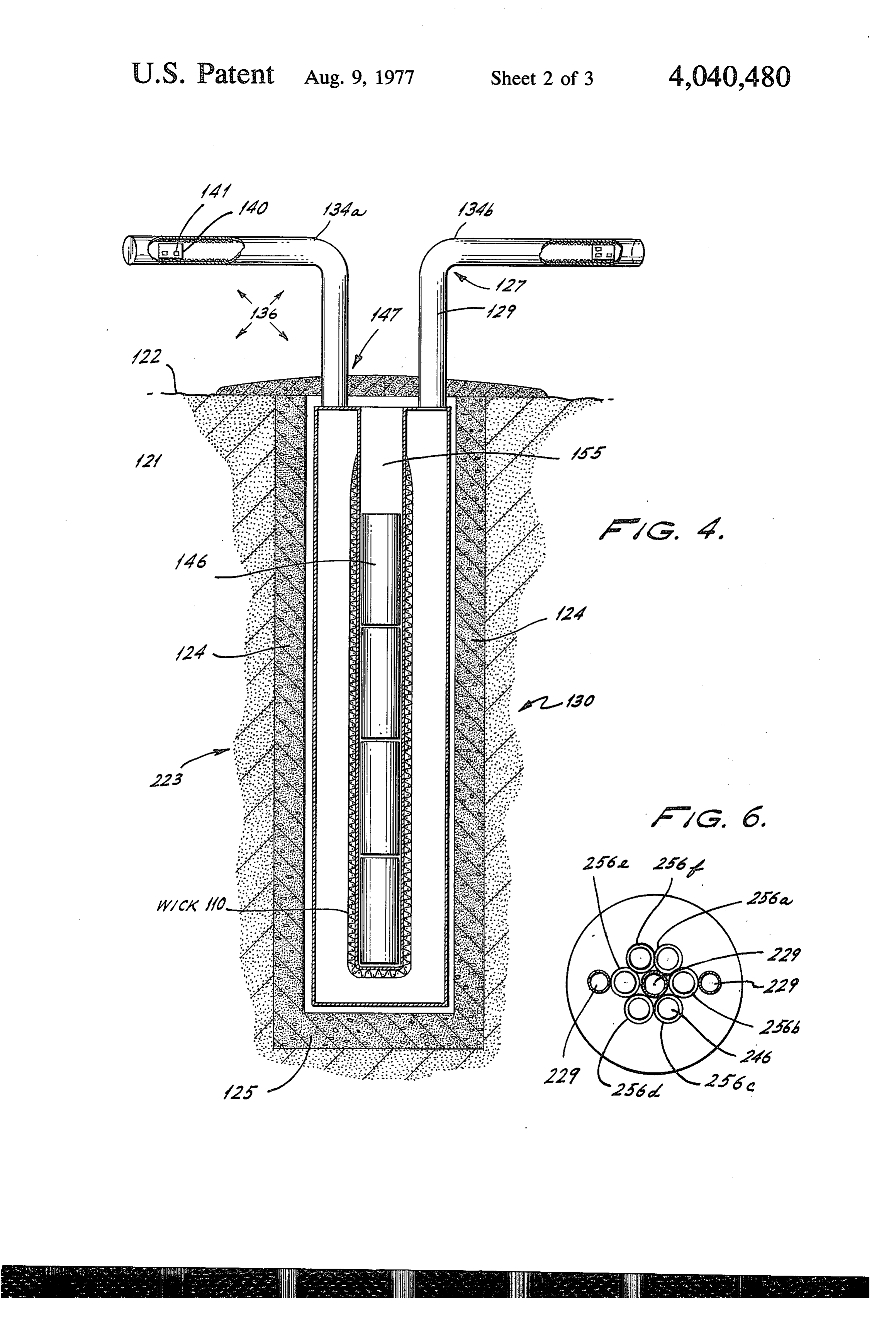
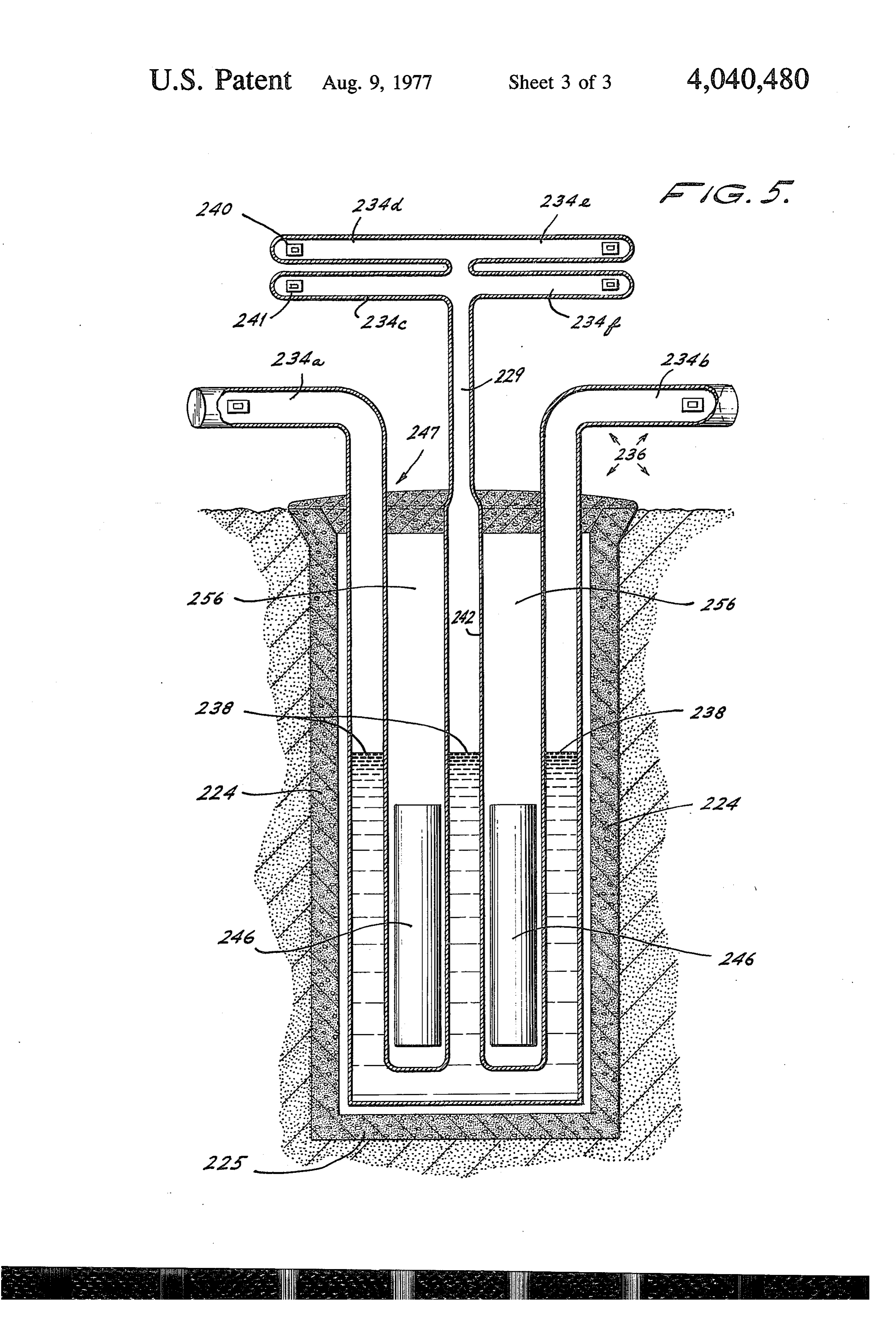
Although there has been a long-standing recognition FIG. 4 is a schematic view of a second embodiment. that heat dissipation systems or cooling systems were FIG. 5 is a schematic view of a third embodiment. needed to cope with the long term storage of radioac 65 FIG. 6 is a top schematic sectional view of the em tive materials, there has been no proposal for a simple bodiment of FIG. 5.
low maintenance system for storage of radioactive ma The invention is further clarified by reference to a terials. plurality of examples.
Page 6
EXAMPLE 1
phies disruptive to the long term storage of radioactive materials.
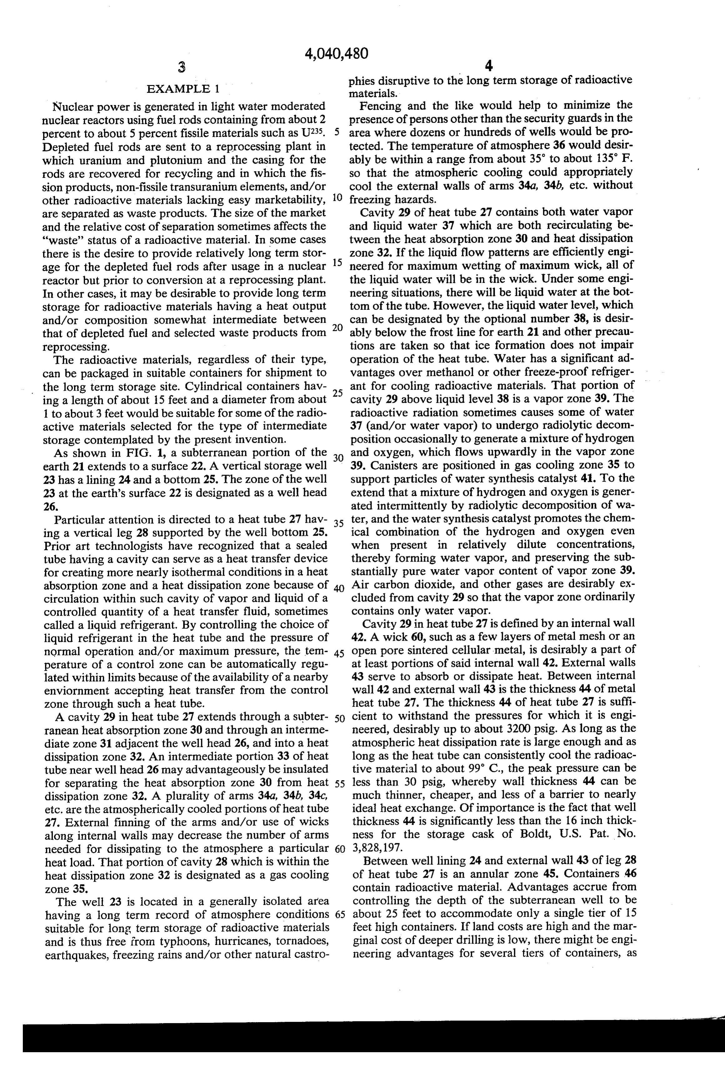
Nuclear power is generated in light water moderated Fencing and the like would help to minimize the nuclear reactors using fuel rods containing from about 2 presence of persons other than the security guards in the percent to about 5 percent fissile materials such as U235. area where dozens or hundreds of wells would be pro Depleted fuel rods are sent to a reprocessing plant in tected. The temperature of atmosphere 36 would desir which uranium and plutonium and the casing for the ably be within a range from about 35' to about 135 F. rods are recovered for recycling and in which the fis so that the atmospheric cooling could appropriately sion products, non-fissile transuranium elements, and/or 10 cool the external walls of arms 34a, 34b, etc. without other radioactive materials lacking easy marketability, freezing hazards.
are separated as waste products. The size of the market Cavity 29 of heat tube 27 contains both water vapor and the relative cost of separation sometimes affects the and liquid water 37 which are both recirculating be "waste” status of a radioactive material. In some cases tween the heat absorption zone 30 and heat dissipation there is the desire to provide relatively long term stor 15 zone 32. If the liquid flow patterns are efficiently engi age for the depleted fuel rods after usage in a nuclear neered for maximum wetting of maximum wick, all of reactor but prior to conversion at a reprocessing plant. the liquid water will be in the wick. Under some engi In other cases, it may be desirable to provide long term neering situations, there will be liquid water at the bot storage for radioactive materials having a heat output tom of the tube. However, the liquid water level, which and/or composition somewhat intermediate between 20 can be designated by the optional number 38, is desir that of depleted fuel and selected waste products from ably below the frost line for earth 21 and other precau reprocessing. tions are taken so that ice formation does not impair The radioactive materials, regardless of their type, operation of the heat tube. Water has a significant ad can be packaged in suitable containers for shipment to vantages over methanol or other freeze-proof refriger the long term storage site. Cylindrical containers hav 25 ant for cooling radioactive materials. That portion of ing a length of about 15 feet and a diameter from about cavity 29 above liquid level 38 is a vapor zone 39. The 1 to about 3 feet would be suitable for some of the radio radioactive radiation sometimes causes some of water active materials selected for the type of intermediate 37 (and/or water vapor) to undergo radiolytic decom storage contemplated by the present invention. position occasionally to generate a mixture of hydrogen As shown in FIG. 1, a subterranean portion of the 30 and oxygen, which flows upwardly in the vapor Zone earth 21 extends to a surface 22. A vertical storage well 39. Canisters are positioned in gas cooling zone 35 to 23 has a lining 24 and a bottom 25. The zone of the well support particles of water synthesis catalyst 41. To the 23 at the earth's surface 22 is designated as a well head extend that a mixture of hydrogen and oxygen is gener 26. ated intermittently by radiolytic decomposition of wa Particular attention is directed to a heat tube 27 hav 35 ter, and the water synthesis catalyst promotes the chem ing a vertical leg 28 supported by the well bottom 25. ical combination of the hydrogen and oxygen even Prior art technologists have recognized that a sealed when present in relatively dilute concentrations, tube having a cavity can serve as a heat transfer device thereby forming water vapor, and preserving the sub for creating more nearly isothermal conditions in a heat stantially pure water vapor content of vapor Zone 39. absorption zone and a heat dissipation zone because of 40 Air carbon dioxide, and other gases are desirably ex circulation within such cavity of vapor and liquid of a cluded from cavity 29 so that the vapor zone ordinarily controlled quantity of a heat transfer fluid, sometimes contains only water vapor.
called a liquid refrigerant. By controlling the choice of Cavity 29 in heat tube 27 is defined by an internal wall liquid refrigerant in the heat tube and the pressure of 42. A wick 60, such as a few layers of metal mesh or an normal operation and/or maximum pressure, the tem 45 open pore sintered cellular metal, is desirably a part of perature of a control zone can be automatically regu at least portions of said internal wall 42. External walls lated within limits because of the availability of a nearby 43 serve to absorb or dissipate heat. Between internal enviornment accepting heat transfer from the control wall 42 and external wall 43 is the thickness 44 of metal zone through such a heat tube. heat tube 27. The thickness 44 of heat tube 27 is suffi A cavity 29 in heat tube 27 extends through a subter 50 cient to withstand the pressures for which it is engi ranean heat absorption zone 30 and through an interme neered, desirably up to about 3200 psig. As long as the diate zone 31 adjacent the well head 26, and into a heat atmospheric heat dissipation rate is large enough and as dissipation zone 32. An intermediate portion 33 of heat long as the heat tube can consistently cool the radioac tube near well head 26 may advantageously be insulated tive material to about 99 C., the peak pressure can be for separating the heat absorption zone 30 from heat 55 less than 30 psig, whereby wall thickness 44 can be dissipation zone 32. A plurality of arms 34a, 34b, 34c, much thinner, cheaper, and less of a barrier to nearly etc. are the atmospherically cooled portions of heat tube ideal heat exchange. Of importance is the fact that well 27. External finning of the arms and/or use of wicks thickness 44 is significantly less than the 16 inch thick along internal walls may decrease the number of arms ness for the storage cask of Boldt, U.S. Pat. No. needed for dissipating to the atmosphere a particular 60 3,828,197.
heat load. That portion of cavity 28 which is within the Between well lining 24 and external wall 43 of leg 28 heat dissipation zone 32 is designated as a gas cooling of heat tube 27 is an annular zone 45. Containers 46 Zone 35. contain radioactive material. Advantages accrue from The well 23 is located in a generally isolated area controlling the depth of the subterranean well to be having a long term record of atmosphere conditions 65 about 25 feet to accommodate only a single tier of 15 suitable for long term storage of radioactive materials feet high containers. If land costs are high and the mar and is thus free from typhoons, hurricanes, tornadoes, ginal cost of deeper drilling is low, there might be engi earthquakes, freezing rains and/or other natural castro neering advantages for several tiers of containers, as
Page 7
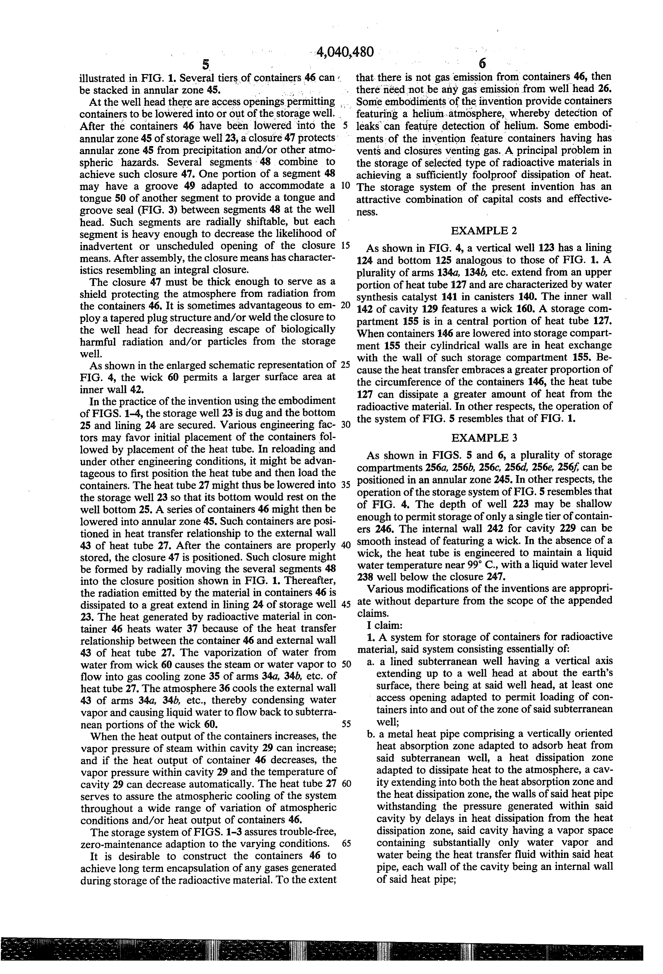
illustrated in FIG. 1. Several tiers of containers 46 can that there is not gas emission from containers 46, then be stacked in annular zone 45. there need not be any gas emission from well head 26. At the well head there are access openings permitting Some embodiments of the invention provide containers containers to be lowered into or out of the storage well. featuring a helium-atmosphere, whereby detection of After the containers 46 have been lowered into the 5 leaks can feature detection of helium. Some embodi annular zone 45 of storage well 23, a closure 47 protects ments of the invention feature containers having has annular zone 45 from precipitation and/or other atmo vents and closures venting gas. A principal problem in spheric hazards. Several segments 48 combine to the storage of selected type of radioactive materials in achieve such closure 47. One portion of a segment 48 achieving a sufficiently foolproof dissipation of heat. may have a groove 49 adapted to accommodate a 10 The storage system of the present invention has an tongue 50 of another segment to provide a tongue and attractive combination of capital costs and effective groove seal (FIG. 3) between segments 48 at the well IeSS.
head. Such segments are radially shiftable, but each EXAMPLE 2 segment is heavy enough to decrease the likelihood of inadvertent or unscheduled opening of the closure 15 As shown in FIG. 4, a vertical well 123 has a lining means. After assembly, the closure means has character 124 and bottom 125 analogous to those of FIG. 1. A istics resembling an integral closure. plurality of arms 134a, 134b, etc. extend from an upper The closure 47 must be thick enough to serve as a portion of heat tube 127 and are characterized by water shield protecting the atmosphere from radiation from synthesis catalyst 141 in canisters 140. The inner wall the containers 46. It is sometimes advantageous to em- 20 142 of cavity 129 features a wick 160. A storage com ploy a tapered plug structure and/or weld the closure to partment 155 is in a central portion of heat tube 127. the well head for decreasing escape of biologically When containers 146 are lowered into storage compart harmful radiation and/or particles from the storage ment 155 their cylindrical walls are in heat exchange well. with the wall of such storage compartment 155. Be As shown in the enlarged schematic representation of 25 cause the heat transfer embraces a greater proportion of FIG. 4, the wick 60 permits a larger surface area at the circumference of the containers 146, the heat tube inner wall 42. 127 can dissipate a greater amount of heat from the In the practice of the invention using the embodiment of FIGS. 1-4, the storage well 23 is dug and the bottom radioactive material. In other respects, the operation of 25 and lining 24 are secured. Various engineering fac 30 the system of FIG. 5 resembles that of FIG. 1. tors may favor initial placement of the containers fol EXAMPLE 3 lowed by placement of the heat tube. In reloading and As shown in FIGS. 5 and 6, a plurality of storage under other engineering conditions, it might be advan compartments tageous to first position the heat tube and then load the positioned in an256a, 256b, 256c, 256d, 256e, 256f can be annular zone 245. In other respects, the containers. The heat tube 27 might thus be lowered into operation of the storage system
the storage well 23 so that its bottom would rest on the of FIG. 4. The depth of wellof223 FIG. 5 resembles that may be shallow well bottom 25. A series of containers 46 might then be lowered into annular zone 45. Such containers are posi enough to permit storage of only a single tier of contain tioned in heat transfer relationship to the external wall ers 246.instead
The internal wall 242 for cavity 229 can be 43 of heat tube 27. After the containers are properly smooth wick, the heat of featuring a wick. In the absence of a tube is engineered to maintain a liquid stored, the closure 47 is positioned. Such closure might be formed by radially moving the several segments 48 water temperature near 99 C., with a liquid water level into the closure position shown in FIG. 1. Thereafter, 238Various well below the closure 247. the radiation emitted by the material in containers 46 is ate withoutmodifications departure of the inventions are appropri from the scope of the appended dissipated to a great extend in lining 24 of storage well 45 23. The heat generated by radioactive material in con claims. I claim:
tainer 46 heats water 37 because of the heat transfer 1. A system for storage of containers for radioactive relationship between the container 46 and external wall material, 43 of heat tube 27. The vaporization of water from said system consisting essentially of: water from wick 60 causes the steam or water vapor to 50 a. extending a lined subterranean well having a vertical axis up to a well head at about the earth's flow into gas cooling zone 35 of arms 34a, 34b, etc. of heat tube 27. The atmosphere 36 cools the external wall surface, there being at said well head, at least one 43 of arms 34a, 34b, etc., thereby condensing water access opening adapted to permit loading of con vapor and causing liquid water to flow back to subterra tainers into and out of the zone of said subterranean nean portions of the wick 60. 55 well;
When the heat output of the containers increases, the b. a metal heat pipe comprising a vertically oriented vapor pressure of steam within cavity 29 can increase; heat absorption zone adapted to adsorb heat from and if the heat output of container 46 decreases, the said subterranean well, a heat dissipation zone vapor pressure within cavity 29 and the temperature of adapted to dissipate heat to the atmosphere, a cav cavity 29 can decrease automatically. The heat tube 27 60 ity extending into both the heat absorption zone and serves to assure the atmospheric cooling of the system the heat dissipation zone, the walls of said heat pipe throughout a wide range of variation of atmospheric withstanding the pressure generated within said conditions and/or heat output of containers 46. cavity by delays in heat dissipation from the heat The storage system of FIGS. 1-3 assures trouble-free, dissipation zone, said cavity having a vapor space zero-maintenance adaption to the varying conditions. 65 containing substantially only water vapor and It is desirable to construct the containers 46 to water being the heat transfer fluid within said heat achieve long term encapsulation of any gases generated pipe, each wall of the cavity being an internal wall during storage of the radioactive material. To the extent of said heat pipe;
Page 8
c. at least one container of radioactive material in heat promoted by metal wicking at at least portions of the exchange relationship with said heat tube in the wall of the cavity.
subterranean heat absorption zone; 3. A system in accordance with claim 1 in which the d. a closure means for the well head of the subterra nean well, such closure means having a heavy upward isradiation closure thick enough to shield the atmosphere from from the containers.
weight adapted to decrease the likelihood of inad vertent or unscheduled opening of said access open 4. A system in accordance with claim 1 in which each ings or shifting of such closure means. container is hermetically sealed to prevent escape of gas 2. A system in accordance with claim 1 in which from such container.
equilibria between the liquid water and water vapor is 10 s
Provenance
- Collection
- Cited prior art
- Original PDF
- patentimages.storage.googleapis.com →
- Filed
- 1976-04-15
- Pages
- 8
- Method
- pdftotext (the PDF's own text layer) + pdftoppm 300dpi page scans
- Source
- Google Patents bibliographic record
- Granted
- 1977-08-09
- Inventors
- Lawrence M. Richards; Atlantic Richfield Co
- Transcribed from
- patentimages.storage.googleapis.com →