patent · US4095429
Solar gravity engine
20 June 1978
Page 1 — bibliographic record
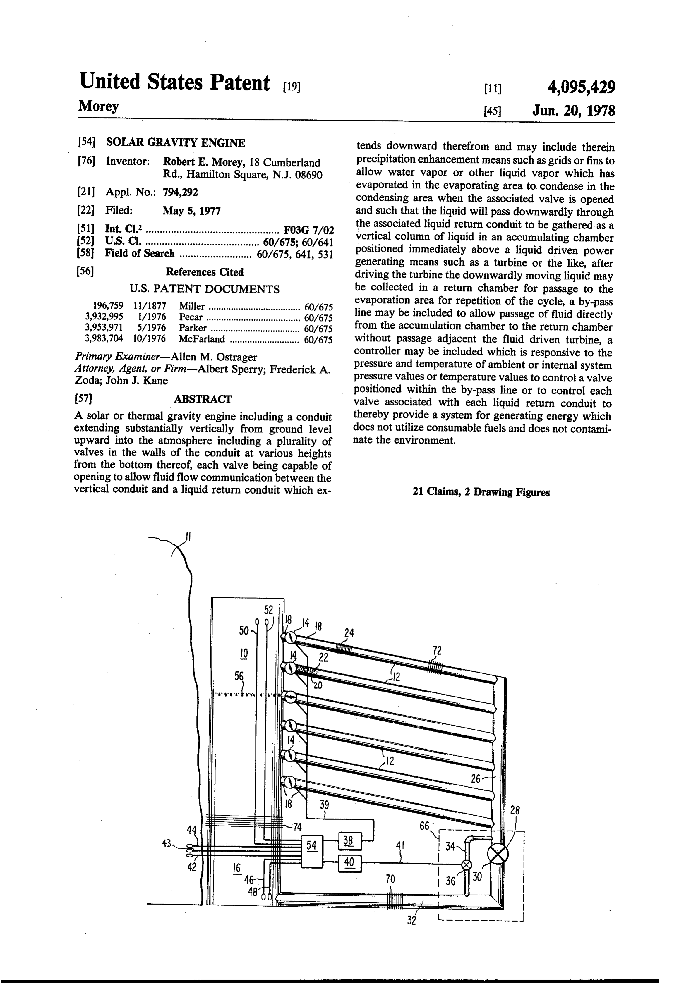
United States Patent (19) 11) 4,095,429 Morey 45) Jun. 20, 1978 (54) SOLAR GRAVITY ENGINE tends downward therefrom and may include therein 76 Inventor: Robert E. Morey, 18 Cumberland precipitation enhancement means such as grids or fins to Rd., Hamilton Square, N.J. 08690 allow water vapor or other liquid vapor which has 21 Appl. No.: 794,292 evaporated in the evaporating area to condense in the condensing area when the associated valve is opened (22 Filed: May 5, 1977 and such that the liquid will pass downwardly through 51) Int. C.’................................................ F03G 7/02 the associated liquid return conduit to be gathered as a 52) U.S. C. ......................................... 60/675; 60/641 vertical column of liquid in an accumulating chamber 58) Field of Search .......................... 60/675, 641, 531 positioned immediately above a liquid driven power generating means such as a turbine or the like, after (56) References Cited driving the turbine the downwardly moving liquid may
196,759 11/1877 Miller ..................................... 60/675 evaporation area for repetition of the cycle, a by-pass 3,932,995 1/1976 Pecar.... 60/675 line may be included to allow passage of fluid directly 3,953,971 5/1976 Parker ... 60/675 from the accumulation chamber to the return chamber 3,983,704 10/1976 McFarland ............................ 60/675 without passage adjacent the fluid driven turbine, a Primary Examiner-Allen M. Ostrager controller may be included which is responsive to the Attorney, Agent, or Firm-Albert Sperry; Frederick A. pressure and temperature of ambient or internal system Zoda; John J. Kane pressure values or temperature values to control a valve positioned within the by-pass line or to control each 57 ABSTRACT valve associated with each liquid return conduit to A solar or thermal gravity engine including a conduit thereby provide a system for generating energy which extending substantially vertically from ground level does not utilize consumable fuels and does not contami upward into the atmosphere including a plurality of nate the environment.
valves in the walls of the conduit at various heights from the bottom thereof, each valve being capable of opening to allow fluid flow communication between the vertical conduit and a liquid return conduit which ex 21 Claims, 2 Drawing Figures
Page 2
Drawing sheet — no readable text.
Page 3
evaporating and condensing system for drawing electri
SOLAR GRAVITY ENGINE cal or other power therefrom.
BACKGROUND OF THE INVENTION
More particularly, the present invention includes a vertically extending conduit which defines therein in 1. Field of the Invention the lower region an evaporating area at which point The present invention deals with the field of gravity liquid is evaporated to move upwardly through the generation systems which are particularly useful since vertical conduit to the upper region thereof. Adjacent they do not involve the consuming of fossil or other the vertical conduit at each altitude is a condensing area fuels while at the same time do not contaminate the defined within the liquid return conduits. At a point atmosphere and environment with undesirable pollut 10 within the condensing area the vapor will precipitate. ants. The source of power is gravity, obtained by the However a plurality of approximately laterally but adiabatic lapse rate between ground level and upper somewhat downwardly extending conduits include atmosphere levels which is inherent most particularly in precipitation enhancement means in order to urge the arid environments. vapor into the condensing area to precipitate upon the For all practical purposes for the present invention 15 enhancement means. This means may be in the form of the source of heat at ground level is infinite as well as is horizontally or laterally extending grids or fins within the difference in temperature between ground level and the liquid conduits.
upper atmospheric levels. As such the present invention The liquid now condensed within the liquid conduits makes use of this functionally infinite heat source at will move downwardly and be gathered at a lower ground level as well as the functionally infinite heat sink 20 altitude in an accumulating chamber which is adapted at upper atmospheric levels in order to generate usable to accumulate therein as a vertically extending column energy to induce a condensing and evaporating cyclical of liquid. This liquid now has stored potential energy system which can be used to generate pollution-free due to its height above the original evaporating area. As electrical or other power outputs. such, the potential energy of this liquid can be con 2. Description of the Prior Art 25 verted into a usable form of energy output by means of Many prior art systems which utilize the principle of a power generator means or fluid driven turbine. After evaporation at ground level and condensing at upper passage adjacent the power generating means the atmospheric levels are inherently impractical and con downwardly moving liquid may be gathered in a return structively cumbersome due to the disproportionate chamber for movement to the evaporating area in order size of structure when considered with respect to the 30 to continue the cyclical operation of the present system. energy output thereof. The present design may over In order to facilitate the control of the amount of come these previous difficulties due to the inherently fluid driving the fluid driven power generating means a closed nature of the general system, most particularly by-pass line may be configured including a valve the system shown in FIG. 1 which is entirely closed, therein which is operable to allow liquid to by-pass the that is, hermetically sealed with respect to the external 35 power generating means and pass directly from the environment. Most prior art systems which utilize this accumulating chamber to the return chamber. In this weather effect require very large rain gathering surface manner the driving of the power generating means can areas. This requirement is not apparent in the present be closely controlled in order to maintain full cyclical system since the entire amount of vapor which evapo operation of the present system while still withdrawing rates and moves upwardly in the vertically extending a usable amount of power therefrom.
conduit is gathered by the predetermined and pre In order to assure full and efficient operation of the chosen liquid conduit and, as such, all of the vapor present system a plurality of sensing means may be which moves upwardly is able to be gathered and utilized in order to sense the external ambient tempera passed through the power generating member. ture, pressure and/or humidity as well as the tempera Also the prior art systems vary in efficiency as the 45 ture and pressure internally within the system. This atmospheric conditions would vary, however, the pres plurality of sensing means may communicate this sensed ent design includes sensing means for varying the opera information to a valve controller. The valve controller tional characteristics of the closed system in response to may be operable to open any one of a plurality of valves the ambient environmental conditions or the internal which are positioned between each liquid conduit and system environmental conditions. In particular, a con 50 the vertically extending conduit. These valves are nor trol means is provided to vary the vertical height at mally closed to prevent fluid flow communication be which the condensed fluid is gathered for passage tween the liquid conduit and the vertical conduit how downwardly to the area of accumulation immediately ever the controller is operable to open a valve which is above the turbine. A control means is included which positioned at approximately the proper vertical height varies at what height this liquid is condensed responsive 55 at which the dew point or point of condensation is to the ambient and internal environmental conditions in presently existing. To determine this altitude and there order to achieve a height which is optimally equal to fore to determine the proper valve to cause to open, the the dew point or point of condensation of the vertically control means senses the ambient and internal environ moving vapor. In this manner the most efficient means mental conditions and after processing does determine of gathering the precipitating vapor is achieved. These which valve should become open.
advantages and other advantages over the prior art will This information communicated by the various sens become apparent upon study of the operational charac ing means is also used by a second controller to open or teristics of the present system. close the valve located within the by-pass line to con
SUMMARY OF THE INVENTION
trol the output of the power generator means and the 65 internal liquid pressure of the "Closed System'.
The present invention provides an engine system for The present system may be entirely closed or hermet utilizing the difference in temperatures and pressures at ically sealed with respect to the ambient environment in vertical heights in the atmosphere for generating an order to receive therefrom and be operated by only the
Page 4
temperature difference between the evaporation area BRIEF DESCRIPTION OF THE DRAWINGS and the condensing area. With such a configuration an internal operating fluid as commonly used as a refriger While the invention is particularly pointed out and ant in refrigerating systems may be used such as ammo distinctly claimed in the concluding portions herein, a nia, Freon, or other suitable substances. Alternatively, preferred embodiment is set forth in the following de the system may be operated in an opened condition in tailed description which may be best understood when which the return chamber is open with respect to a read in connection with the accompanying drawings, in surrounding environment in order to receive water which:
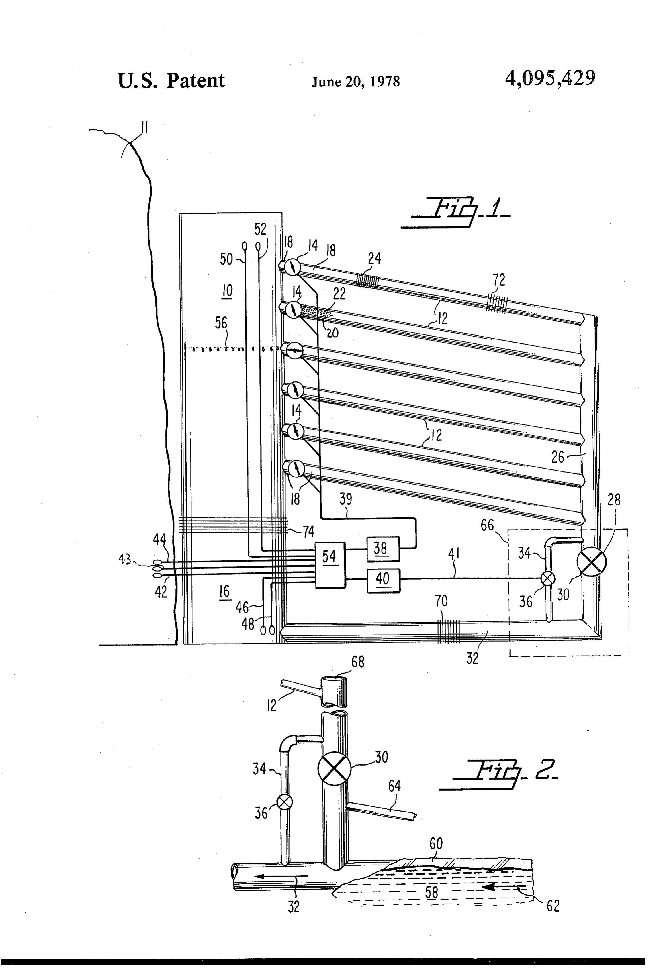
vapor and water therefrom. With this system the oper FIG. 1 is a schematic representation of an embodi ating fluid within the engine will be water and an addi 10 ment of the present invention in which the internal tional by-product thereof will be the availability of environment is hermetically sealed with respect to the potable water or irrigation water immediately down ambient environment; and stream from the location of the fluid driven turbine. FIG. 2 is an alternative schematic embodiment of the Also when using the opened system the ambient exter configuration shown in FIG. 1 wherein the internal nal barometric pressure and humidity must be sensed 15 environment of the system is in fluid flow communica since these indices now have an important bearing upon tion with the external ambient environment. the operating characteristics between the evaporating area and the condensing area within the vertically ex DETALED DESCRIPTION OF THE tending conduit. As such the sensing means should be PREFERRED EMBODIMENT constructed to additionally utilize this information in 20 FIG. 1 illustrates an embodiment of the thermal grav order to vary the positioning of the valves adjacent the ity engine of the present invention. A conduit 10 is areas of condensation as well as for controlling the shown extending from an approximately ground level valve within the by-pass line. vertically upward to a higher altitude. The conduit 10 It is an object of the present invention to generate defines a chamber usable energy without pollution of the external ambient proximately groundtherein
level where a lower region at ap comprises an evaporating environment.
area 16. The upper level of
It is an object of the present invention to generate nicates with a plurality of liquidthe vertical conduit commu usable energy without requiring consumption of fossil each return conduits 12, or other consumable fuels. of which defines a condensing area 18. The con It is an object of the present invention to provide a 30 duit 10 should be of sufficient height to establish a sub means for generation of energy merely utilizing the stantial difference between the external ambient temper ature at the evaporator area 16 from the external tem difference in temperatures between differing altitudes perature within the atmosphere. adjacent of the condensing area 18. Generally It is an object of the present invention to provide a speaking the vertical conduit 10 should extend as high system for gathering of condensed fluid in order to 35 as structurally feasible. In order to facilitate support of provide a source of energy which may readily be such a vertical construction it may be deemed advisable tapped for a variety of purposes. to construct this conduit immediately adjacent to some It is an object of the present invention to provide a other vertically extending element such as a mountain practical system for harnessing the potential energy 11. It may indeed be feasible to place the conduit 10 stored by the vertical movement of water vapor due to adjacent to a mountain such that the conduit extends downwardly into the valley therebelow and thereby the normal evaporation and condensing cycle.
It is an object of the present invention to provide a minimize the strengthening structures required in the means to economically produce potable water from overall construction.
saline and/or chemically contaminated water, without A plurality of liquid return conduits 12 will be posi fossil or nuclear energy input. 45 tioned for fluid flow communication with the upper It is an object of the present invention to provide a region of conduit 10 at various vertical altitudes therein. source of potable water or irrigation water. The liquid return conduits will be affixed to the wall of It is an object of the present invention to provide a the conduit 10 at a different vertical altitude in order to means of gathering precipitating water vapor which allow for varying heights of the point of condensation may be varied as to vertical levels in accordance with 50 responsive to environmental conditions. In the normal the constantly varying dew point or point of condensa operation of the system only the single or multiple liq tion. uid return conduits 12 at the same height will be utilized It is an object of the present invention to provide a and all the non-operating conduits 12 which are at other system for the storage of kinetic energy by the holding altitudes will be closed. Valve means 14 within each of of liquid within a chamber at a height well above 55 the conduits 12 will be normally closed and will be ground level. opened when actuated to allow condensing in the inter It is an object of the present invention to sense ambi nal environment of the liquid conduit 12. ent external environmental characteristics and to com In order to facilitate condensing of vapor within the pute the height of the dew point at any particular liquid return conduits 12 a precipitation enhancement chosen time and to cause precipitation of water vapor means 20 such as grid means 22 or fin means 24 may be or other vapor at approximately that vertical altitude. located therein. More particularly the grid means may It is an object of the present invention to take advan be in the form of a wire mesh or the like extending tage of the adiabatic lapse rate of the atmosphere in across and throughout the interior of the return conduit order to harness usable energy. 12 in order to provide a location for the vapor to precip It is an object of the present invention to enhance 65 itate. Alternatively a plurality of fins 24 may be posi precipitation of vapor at a substantial vertical altitude tioned annularly around the internal radius of the con and to gather the liquid so precipitated to provide a duit 12 to operate similarly while still allowing fluid usable source of energy. flow through the conduit 14.
Page 5
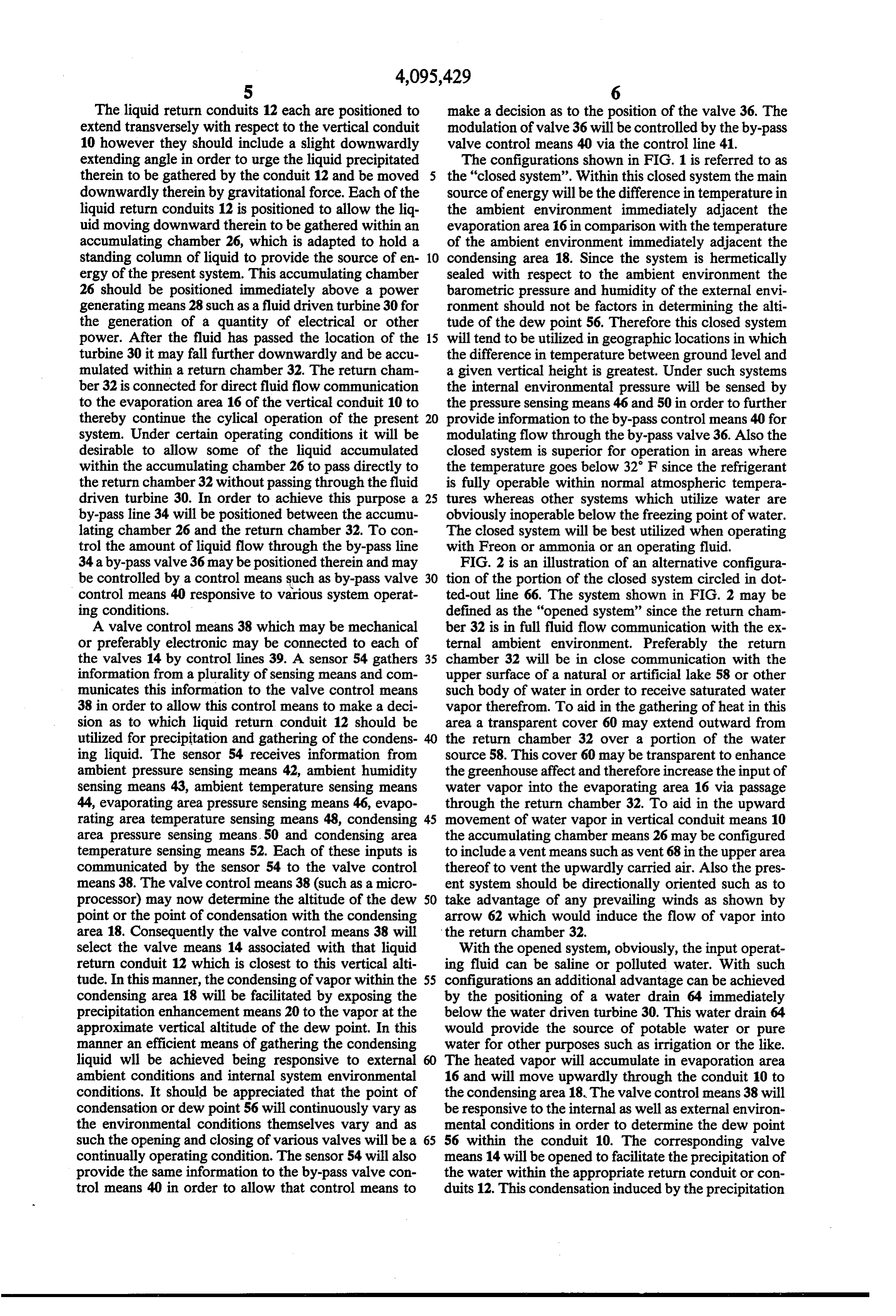
The liquid return conduits 12 each are positioned to make a decision as to the position of the valve 36. The extend transversely with respect to the vertical conduit modulation of valve 36 will be controlled by the by-pass 10 however they should include a slight downwardly valve control means 40 via the control line 41. extending angle in order to urge the liquid precipitated The configurations shown in FIG. 1 is referred to as therein to be gathered by the conduit 12 and be moved the "closed system'. Within this closed system the main downwardly therein by gravitational force. Each of the source of energy will be the difference in temperature in liquid return conduits 12 is positioned to allow the liq the ambient environment immediately adjacent the uid moving downward therein to be gathered within an evaporation area 16 in comparison with the temperature accumulating chamber 26, which is adapted to hold a of the ambient environment immediately adjacent the standing column of liquid to provide the source of en 10 condensing area 18. Since the system is hermetically ergy of the present system. This accumulating chamber sealed with respect to the ambient environment the 26 should be positioned immediately above a power barometric pressure and humidity of the external envi generating means 28 such as a fluid driven turbine 30 for ronment should not be factors in determining the alti the generation of a quantity of electrical or other tude of the dew point 56. Therefore this closed system power. After the fluid has passed the location of the 15 will tend to be utilized in geographic locations in which turbine 30 it may fall further downwardly and be accu the difference in temperature between ground level and mulated within a return chamber 32. The return cham a given vertical height is greatest. Under such systems ber 32 is connected for direct fluid flow communication the internal environmental pressure will be sensed by to the evaporation area 16 of the vertical conduit 10 to the pressure sensing means 46 and 50 in order to further thereby continue the cylical operation of the present 20 provide information to the by-pass control means 40 for system. Under certain operating conditions it will be modulating flow through the by-pass valve 36. Also the desirable to allow some of the liquid accumulated closed system is superior for operation in areas where within the accumulating chamber 26 to pass directly to the temperature goes below 32 F since the refrigerant the return chamber 32 without passing through the fluid is fully operable within normal atmospheric tempera driven turbine 30. In order to achieve this purpose a 25 tures whereas other systems which utilize water are by-pass line 34 will be positioned between the accumu obviously inoperable below the freezing point of water. lating chamber 26 and the return chamber 32. To con The closed system will be best utilized when operating trol the amount of liquid flow through the by-pass line with Freon or ammonia or an operating fluid. 34 a by-pass valve 36 may be positioned therein and may FIG. 2 is an illustration of an alternative configura be controlled by a control means such as by-pass valve 30 tion of the portion of the closed system circled in dot control means 40 responsive to various system operat ted-out line 66. The system shown in FIG. 2 may be ing conditions. defined as the "opened system' since the return cham A valve control means 38 which may be mechanical ber 32 is in full fluid flow communication with the ex or preferably electronic may be connected to each of ternal ambient environment. Preferably the return the valves 14 by control lines 39. A sensor 54 gathers 35 chamber 32 will be in close communication with the information from a plurality of sensing means and com upper surface of a natural or artificial lake 58 or other municates this information to the valve control means such body of water in order to receive saturated water 38 in order to allow this control means to make a deci vapor therefrom. To aid in the gathering of heat in this sion as to which liquid return conduit 12 should be area a transparent cover 60 may extend outward from utilized for precipitation and gathering of the condens the return chamber 32 over a portion of the water ing liquid. The sensor 54 receives information from source 58. This cover 60 may be transparent to enhance ambient pressure sensing means 42, ambient humidity the greenhouse affect and therefore increase the input of sensing means 43, ambient temperature sensing means water vapor into the evaporating area 16 via passage 44, evaporating area pressure sensing means 46, evapo through the return chamber 32. To aid in the upward rating area temperature sensing means 48, condensing 45 movement of water vapor in vertical conduit means 10 area pressure sensing means 50 and condensing area the accumulating chamber means 26 may be configured temperature sensing means 52. Each of these inputs is to include a vent means such as vent 68 in the upper area communicated by the sensor 54 to the valve control thereof to vent the upwardly carried air. Also the pres means 38. The valve control means 38 (such as a micro ent system should be directionally oriented such as to processor) may now determine the altitude of the dew 50 take advantage of any prevailing winds as shown by point or the point of condensation with the condensing arrow 62 which would induce the flow of vapor into area 18. Consequently the valve control means 38 will the return chamber 32.
select the valve means 14 associated with that liquid With the opened system, obviously, the input operat return conduit 12 which is closest to this vertical alti ing fluid can be saline or polluted water. With such tude. In this manner, the condensing of vapor within the 55 configurations an additional advantage can be achieved condensing area 18 will be facilitated by exposing the by the positioning of a water drain 64 immediately precipitation enhancement means 20 to the vapor at the below the water driven turbine 30. This water drain 64 approximate vertical altitude of the dew point. In this would provide the source of potable water or pure manner an efficient means of gathering the condensing water for other purposes such as irrigation or the like. liquid will be achieved being responsive to external 60 The heated vapor will accumulate in evaporation area ambient conditions and internal system environmental 16 and will move upwardly through the conduit 10 to conditions. It should be appreciated that the point of the condensing area 18. The valve control means 38 will condensation or dew point 56 will continuously vary as be responsive to the internal as well as external environ the environmental conditions themselves vary and as mental conditions in order to determine the dew point such the opening and closing of various valves will be a 65 56 within the conduit 10. The corresponding valve continually operating condition. The sensor 54 will also means 14 will be opened to facilitate the precipitation of provide the same information to the by-pass valve con the water within the appropriate return conduit or con trol means 40 in order to allow that control means to duits 12. This condensation induced by the precipitation
Page 6
enhancement means 20 will decrease the pressure in the may also be configured with similar thermal flow en condensing area 18 slightly and will provide a slight hancement means 72 and 70, respectively. In this man updraft moving from the evaporating area 16 to the ner the differences in temperature which the present condensing area 18 which will further enhance the system utilizes as a means of generating energy will be vaporizing of liquid in the evaporating area 16. It of more effectively communicated to the interior of the course should be appreciated that this system would not system from the ambient environment. function well within an environment which very often While particular embodiments of this invention have includes temperature variations below the freezing tem been shown in the drawings and described above, it will perature of water. However in the warmer arid temper be apparent that many changes may be made in the atures the open system has many advantages since rapid 10 form, arrangement and positioning of the various ele evaporation of water is common. ments of the combination. In consideration thereof it To facilitate the transfer of heat the cover 60 may be should be understood that preferred embodiments of transparent, also the walls of the enclosed vertical con this invention disclosed herein are intended to be illus duit 10 may be transparent to enhance thermal flow between the external ambient environment and the inte 15 trative only and not intended to limit the scope of the invention.
rior of conduit 10. While the size of the vertical conduit I claim:
10 is anticipated to be as large as physically feasible it 1. A solar gravity engine comprising: should be appreciated that it would be virtually impossi (a) a substantially vertical conduit means including an ble to provide any appreciable decrease in the ground evaporating area in a lower region thereof; level temperature or any appreciable increase in the 20 (b) a plurality of liquid return conduit means each upper altitude temperature due to the evaporating con being attached at different vertical locations to said densing cycle within the present thermal gravity en vertical conduit for selective condensation and gine. As such the present invention makes use of this fluid flow therewith, each of said liquid return infinite source of heat at evaporation level and the infi conduit means defining a condensing area therein nite heat sink at higher altitudes to provide a continuing 25 source of usable electrical or other energy. in the region adjacent said vertical conduit means; It should be appreciated that the configuration shown (c) a plurality of first valve means each one positioned in FIG. 1 is merely a preferred embodiment of the gen in the fluid flow path between said vertical conduit eral present invention. In particular the vertical conduit means and one of said return conduit means to means 10 may include a plurality of vertically extending 30 selectively control fluid flow from said vertical conduits. More particularly the liquid return conduit 12 conduit means to the associated return conduit at a given location may comprise a plurality of liquid means;
return conduits 12 extending outwardly radially from a (d) an accumulating chamber means being in fluid central vertical conduit means and in that way provide flow communication with the output of said return a plurality of areas for condensing of the upwardly 35 conduit means to receive and accumulate con moving vapor. With this configuration the openings in densed fluid therefrom; the wall of the vertical conduit at a given height would (e) a return chamber means connected for fluid flow connect to a plurality of liquid return conduits 12 which communication between said accumulating cham extend radially outward from this central location. ber means and said evaporating area to allow liquid Each of these conduits 12 would include therein a valve to return from said accumulating chamber means means 14 as well as precipitation enhancement means to said vertical conduit means; 20. Also the liquid return chamber 32 could comprise a (f) power generating means positioned adjacent the plurality of conduits extending similarly radially out fluid flow path from said accumulating chamber ward from the evaporation area 16 of the vertically means to said return chamber means and adapted to extending conduit 10. In this manner the amount of heat 45 be activated by liquid movement therealong to transfer between the external ambient environment and produce usable energy;
the multiple conduit 32 would be increased. Similarly (g) a by-pass line connected between said accumulat when using multiple liquid return conduits 12 at a single ing chamber means and said return chamber to given height and when utilizing multiple vertically ex allow a controlled amount of condensed liquid to tending conduits 10 the amount of heat transfer between 50 flow from said accumulating chamber means to the external ambient environment and the internal envi said return chamber means without passing adja ronment is increased and the operating volume of the cent said power generating means; entire apparatus is similarly increased. (h) a second valve means positioned within said by The power generating means 28 could also be formed pass line to modulate flow therethrough; as a multiplicity of individual power generating stations 55 (i) first control means to modulate fluid flow through all placed in series immediately downstream from the each of said first valve means; and accumulating chamber means 26. In this manner the (j) second control means to modulate flow through total amount of internal pressure created by the verti said second valve means, cally standing column could be gradually reduced at 2. The engine as defined in claim 1 further comprising each station in order to eliminate the entire amount of 60 ambient sensing means for sensing ambient external downwardly extending pressure being exerted solely environmental conditions and communicating the against a single power generating means. sensed information to said first control means and said In order to enhance the transfer of heat between the second control means.
external ambient environment and the internal environ 3. The engine as defined in claim 1 further comprising ment of the system the vertically extending conduit may 65 system sensing means for sensing environmental condi be configured with a plurality of external fins or other tions within the internal system of the thermal gravity thermal flow enhancement means 74. The liquid return engine and communicating the sensed information to conduit means and the liquid return chamber means said first control means and said second control means.
Page 7
4. The engine as defined in claim 3 wherein said sys densing area in the region thereof adjacent said ten sensing means includes a temperature sensing vertical conduit means;
CS (c) precipitation enhancement means within said liq 5. The engine as defined in claim 3 wherein said sys uid return conduit means to facilitate condensing of tem sensing means includes a pressure sensing means. vapor thereon;
6. The engine as defined in claim 1 including precipi (d) a plurality of first valve means each one posi tation enhancement means located within said return tioned in the fluid flow path between said vertical conduits means and said condensing area to facilitate conduit means and one of said liquid return conduit and enhance condensation of vapor therein. means to control fluid flow from said vertical con 7. The engine as defined in claim 6 wherein said pre O duit means to the associated return conduit means; cipitation enhancement means includes grid means (e) an accumulating chamber means being in fluid within the fluid flow path of each of said liquid return flow communication with the output of said liquid conduit means. return conduit means to receive and accumulate 8. The engine as defined in claim 6 wherein said pre condensed fluid therefrom; cipitation enhancement means includes interior fin 15 (f) a return chamber means connected for fluid flow means within the fluid flow path of each of said liquid communication between said accumulating cham return conduit means. ber means and said evaporation area of said vertical 9. The engine as defined in claim 1 wherein said conduit means to allow liquid to return from said power generating means is a fluid-driven turbine. accumulating chamber means to said vertical con 10. The engine as defined in claim 1 wherein said first 20 duit means and provide a closed system sealed control means and said second control means are elec hermetically with respect to the ambient environ tronic. ment;
11. The engine as defined in claim 1 wherein said (g) fluid-driven turbine means positioned adjacent the vertical conduit means is formed of thermally conduc 25 fluid flow path from said accumulating chamber tive material to facilitate heat transfer between the inte means to said return chamber means and adapted to rior of said vertical conduit means and said return be activated by liquid movement therealong to chamber means with the ambient external environment. produce usable energy;
12. The engine as defined in claim 1 wherein the (h) a by-pass line connected between said accumulat cyclical fluid flow path from said vertical conduit 30 ing chamber means and said return chamber means means to said return conduit means to said accumulat to allow a controlled amount of condensed liquid to flow from said accumulating chamber means to ing chamber means to said return chamber means and said return chamber means without passing adja said by-pass line is hermetically sealed from the external cent said fluid-driven turbine means; ambient environment. (i) a second valve means positioned within said by 13. The engine as defined in claim 12 further includ 35 pass line to modulate flow therethrough; ing freon as the liquid and vapor fluid passing cyclically (j) a first control means to modulate fluid flow through the system. through each of said first valve means; 14. The engine as defined in claim 12 further includ (k) second control means to modulate flow through ing ammonia as the liquid and vapor fluid passing cycli said second valve means; and cally through the system. (l) system temperature sensing means and system 15. The engine as defined in claim 1 wherein said pressure sensing means for sensing environmental accumulating chamber means includes a vent means to conditions within the internal system of the ther the ambient in the upper area thereof. mal gravity engine and communicating said infor 16. The engine as defined in claim 1 wherein said mation to said first control means and said second return chamber means is open with respect to the sur 45 control means.
rounding environment to receive water and water 21. A thermal gravity engine comprising: vapor therefrom for passage to said evaporation area. (a) a substantially vertical conduit means including 17. The engine as defined in claim 16 further compris transparent walls and further including an evapo ing a water drain positioned adjacent said power gener rating area in a lower region thereof; ation means to receive potable condensed water from 50 (b) a plurality of water return conduits each being said accumulating chamber. attached at different vertical locations to said verti 18. The engine as defined in claim 1 further including cal conduit for selective fluid flow therewith, said thermal flow enhancement means on the exterior of said water return conduits defining a condensing area vertical conduit means, said liquid return conduit means therein in the region adjacent said vertical conduit and said return chamber means. 55 means;
19. The engine as defined in claim 1 wherein said (c) precipitation enhancement means to facilitate con power generating means comprises a plurality of power densing of water vapor therein; generating stations placed in series within the liquid (d) a plurality of first valve means each one posi flow path from said accumulating chamber means to tioned in the fluid flow path between said vertical said return chamber means. 60 conduit means and one of said return conduit 20. A thermal gravity engine comprising: means to control fluid flow from said vertical con (a) a substantially vertical conduit means including duit means to the associated return conduit means; transparent walls and further including an evapora (e) an accumulating chamber means being in fluid tion area in a lower region thereof; flow communication with the output of said return (b) a plurality of liquid return conduit means each conduit means to receive and accumulate water being attached at different vertical locations to said therefrom, said accumulating chamber means in vertical conduit for selective fluid flow therewith, cluding a vent means in the upper area thereof to said liquid return conduit means defining a con the ambient environment;
Page 8
(f) a return chamber means for fluid flow communica said return chamber means without passing adja tion between said accumulating chamber means cent said fluid-driven turbine means; and said evaporating area of said vertical conduit (i) a second valve means positioned within said by to allow water to return from said accumulating pass line to modulate flow therethrough; chamber means to said vertical conduit means, said return chamber means being open with respect to (j) first control means to modulate fluid flow through the surrounding environment to receive water and each of said first valve means; water vapor therefrom for passage to said vertical (k) second control means to modulate flow through conduit means; said second valve means;
(g) fluid-driven turbine means positioned adjacent the 10 (l) system temperature sensing means and system fluid flow path from said accumulating chamber pressure sensing means for sensing environmental means to said return chamber means and adapted to conditions for communication of the sensed infor be activated by water movement therealong to mation to said first control means and said second produce usable energy; control means; and (h) a by-pass line connected between said accumulat 15 (m) a water drain positioned adjacent said fluid ing chamber means and said return chamber means driven turbine means to receive potable condensed to allow a controlled amount of condensed water water from said accumulating chamber means. to flow from said accumulating chamber means to
Provenance
- Collection
- Cited prior art
- Original PDF
- patentimages.storage.googleapis.com →
- Filed
- 1977-05-05
- Pages
- 8
- Method
- pdftotext (the PDF's own text layer) + pdftoppm 300dpi page scans
- Source
- Google Patents bibliographic record
- Granted
- 1978-06-20
- Inventors
- Robert E. Morey
- Transcribed from
- patentimages.storage.googleapis.com →