patent · US3985118
Solar furnace
12 October 1976
Page 1
United States Patent (19) 11, 3,985,118 Bard (45) Oct. 12, 1976
(54) soLAR FURNACE Primary Examiner-Kenneth W. Sprague 76 Inventor: Robert F. Bard, 1201 S.W. Cardinell Attorney, Agent, or Firm-James D. Givnan, Jr. Drive, Portland, Oreg. 97201
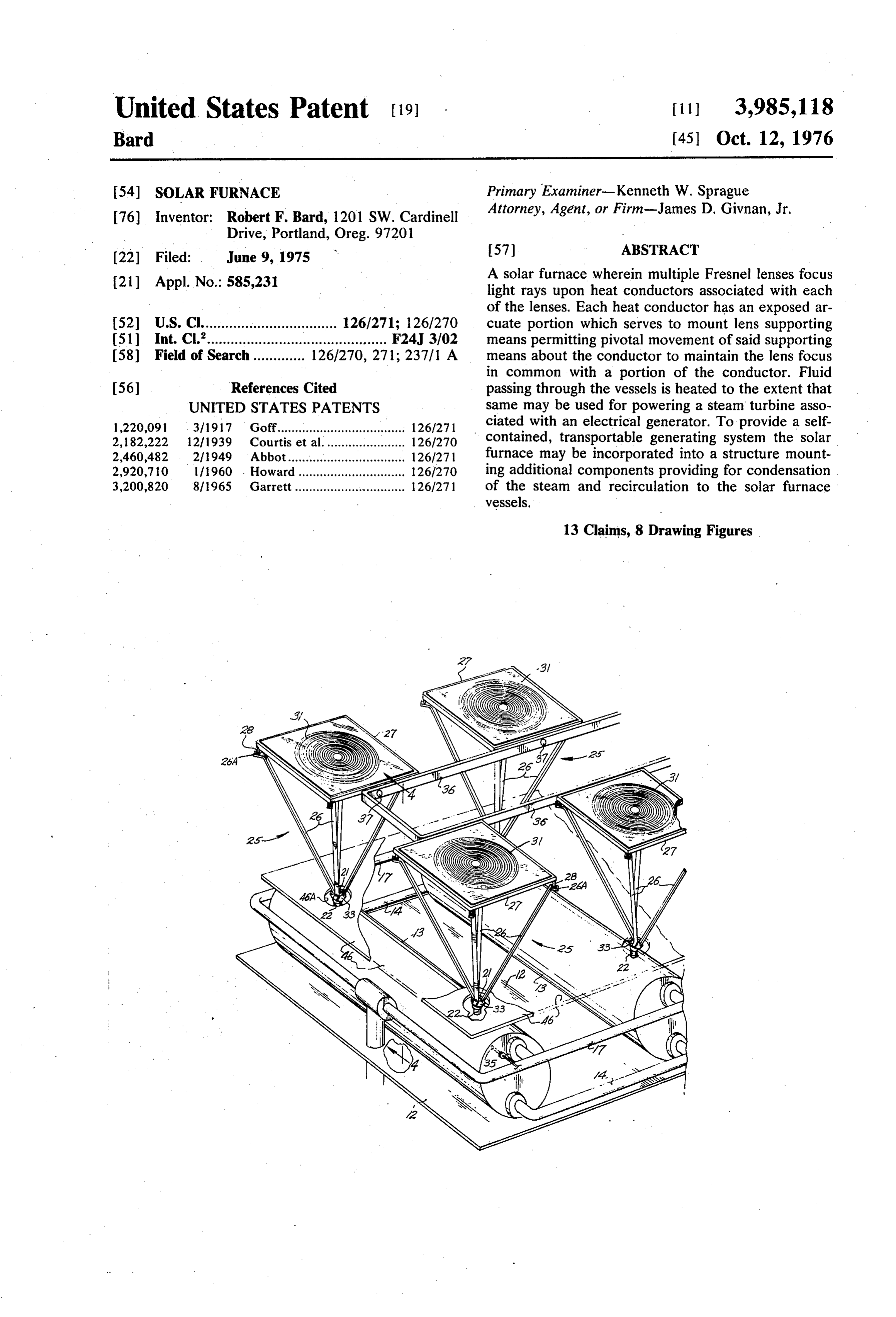
21) Appl. No.: 585,231 A solar furnace wherein multiple Fresnel lenses focus light rays upon heat conductors associated with each of the lenses. Each heat conductor has an exposed ar 52 U.S. Cl.................................. 126/271; 126/270 cuate portion which serves to mount lens supporting (51) int. C.’............................................. F24, 3/02 means permitting pivotal movement of said supporting (58) Field of Search............. 126/270, 271; 237/1 A means about the conductor to maintain the lens focus in common with a portion of the conductor. Fluid 56) References Cited passing through the vessels is heated to the extent that UNITED STATES PATENTS same may be used for powering a steam turbine asso 1,220,091 3/1917 Goff.................................... 126/271 ciated with an electrical generator. To provide a self 2, 182,222 12/1939 Courtis et al............ ... 126/270 contained, transportable generating system the solar 2,460,482 2/1949 Abbot...................... ... 126/27 furnace may be incorporated into a structure mount 2,920,710 11960 . ... 126/270 ing additional components providing for condensation 3,200,820 8/1965 Garrett............................... 1261271 of the steam and recirculation to the solar furnace vessels.
13 Claims, 8 Drawing Figures
Page 2
Drawing sheet — no readable text.
Page 3
Drawing sheet — no readable text.
Page 4
Drawing sheet — no readable text.
Page 5
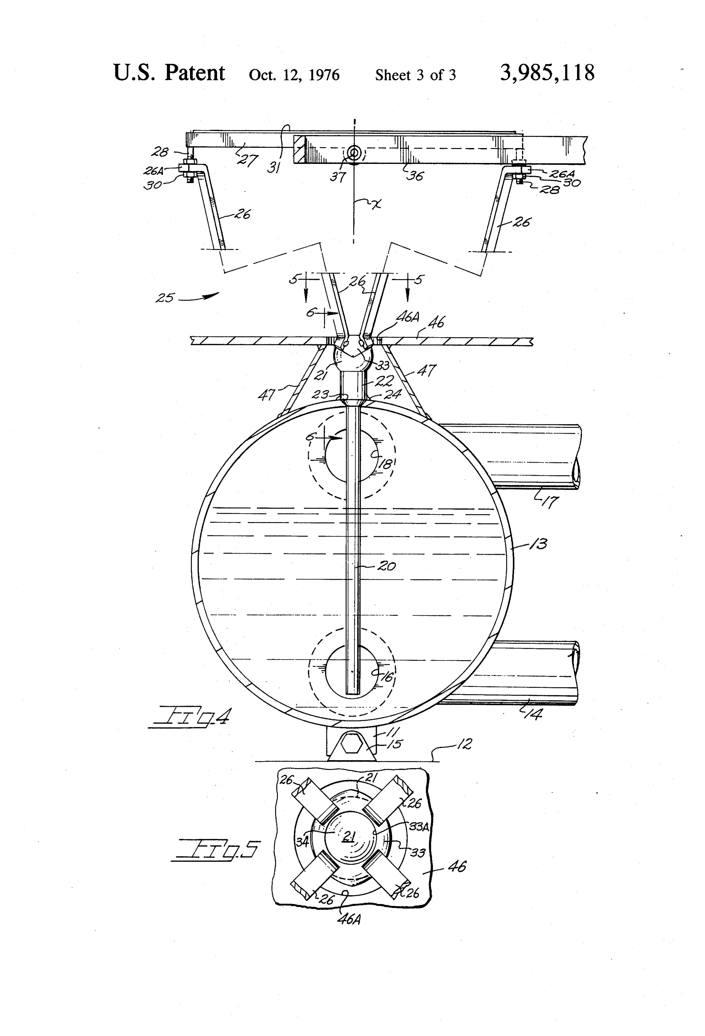
FIG. 5 is a sectional view taken downwardly along
SOLAR FURNACE line 5-5 of FIG. 4 showing details of a pivotal connec tion between a lens assembly and subjacent heat con
BACKGROUND OF THE INVENTION ductor,
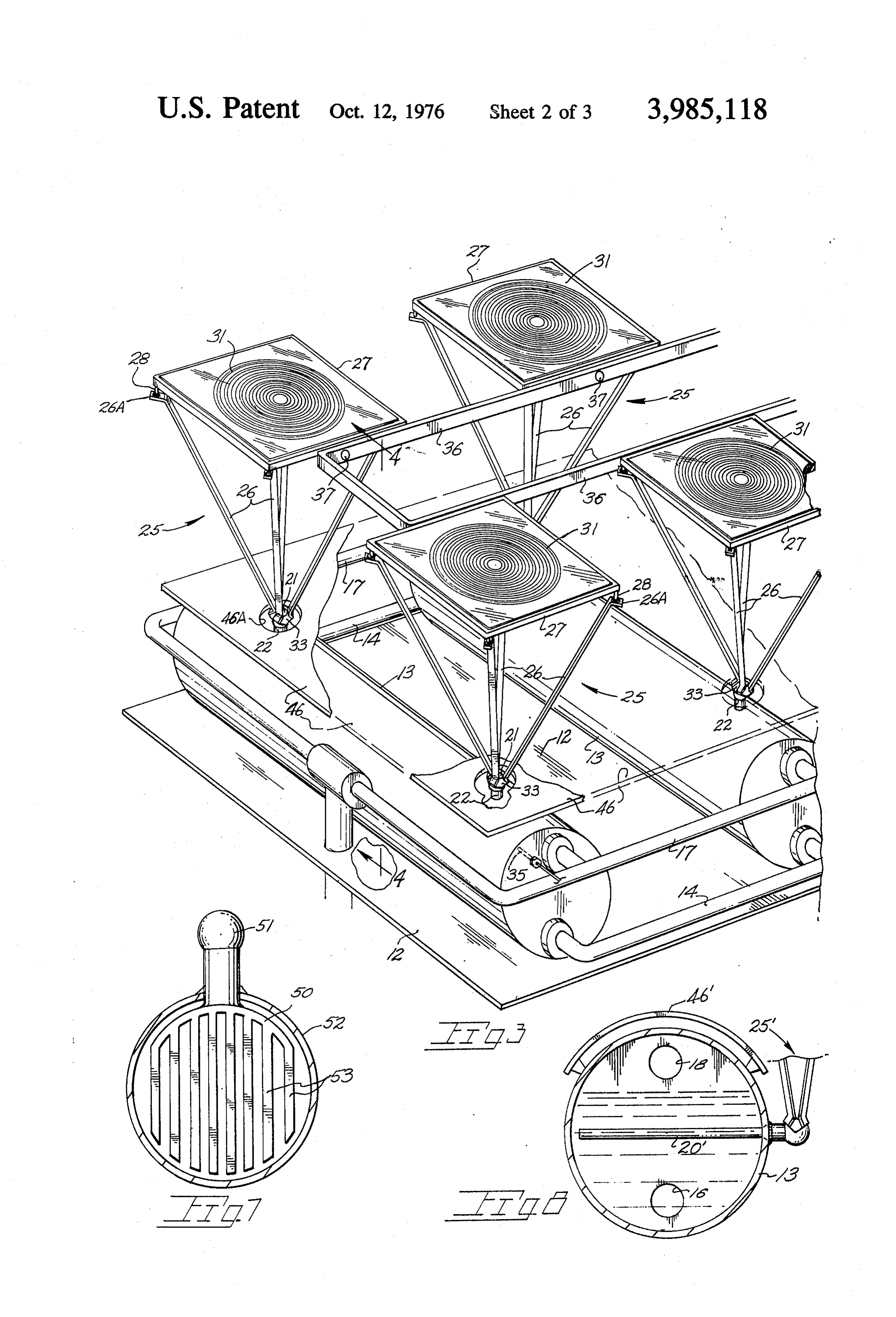
The present invention relates generally to solar fur FIG. 6 is an elevational view taken approximately naces and more particularly to one particularly suited along line 6-6 of FIG. 4 disclosing heat conductor and to heating a transient fluid flow. Solar furnaces as pres lens supporting means details, ently known, incorporate complex lens or reflector FIG. 7 is an end view of a heat conductor modified to arrangements for converging solar rays. Such arrange impart heat to a passing airflow, and ments usually include a battery of lenses mounted in a 10 FIG. 8 is a vertical, sectional view of a modified form movable manner by complex assemblies necessary to of tank and heat conductor combination. accomplish continuous convergence of light rays DESCRIPTION OF THE PREFERRED toward some type of heat exchanger. Lenses used are EMBODIMENT of biconvex nature and hence of substantial cost which, along with their complex support assemblies, renders 5 Subject matter, hereinafter disclosed, was recorded the solar furnace impractical for use other than for very in the U.S. Patent Office under Disclosure Document large size installations or experimental uses. No. 39,127 filed Mar. 17, 1975.
SUMMARY OF THE INVENTION
With continuing reference to the accompanying drawings wherein applied reference numerals indicate
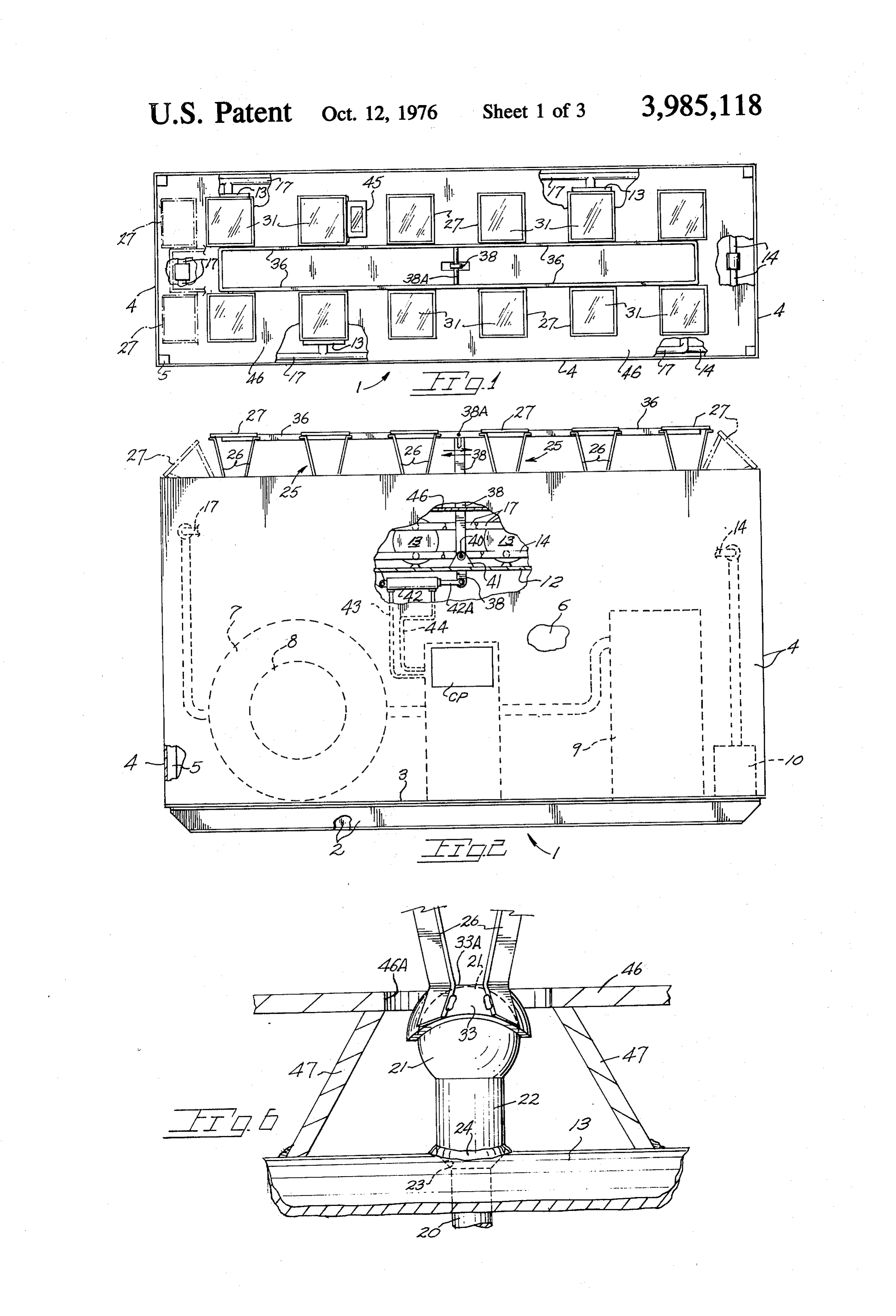
The present invention is embodied within a solar 20 parts similarly identified in the following description, furnace wherein fluid flows through vessels are heated the reference numeral 1 indicates generally a solar by heat conductors which serve additionally to support powered generator structure adapted for unitary trans a lens assembly in a positionable manner. The solar port to a temporary or permanent using site. The struc furnace produces a heated flow of fluid which, in one 25 ture includes a base 2 consisting of lengthwise extend embodiment, is steam for powering an electrical gener ing I-beams and floor 3 providing rigidity to the struc ator. The present solar furnace enables an electrical ture permitting same to be readily transported. Walls at power generating system to be self-contained in a 4 are supported by upright structural members 5 the highly compact manner rendering the system suitable walls defining an equipment bay 6 for the following for transport to a temporary or permanent use site. 30 described generating system components. A turbine 7 Other applications of the heated fluid flow, whether it drives a generator 8 with a condenser tank indicated at be liquid or gaseous, are also later enumerated. 9. A pump 10, suitably powered, draws fluid from the The heat conductors extend into their respective condenser tank for delivery through a manifold system vessels while an exposed end of each conductor sup later described.
ports the lens assembly for sun tracking movement 35 It will be realized that while the system shown is for about at least one axis. A heat barrier serves to prevent generating electrical power other uses of the heat pro undesired heat loss from the vessels. A pivotal connec duced by the following described solar furnace are tion between the lens assemblies and their respective equally feasible.
heat conductors additionally serves to admit solar rays Indicated at 12 is a raised, furnace floor on which onto the heat conductor. vessels or tanks 13 are mounted. Lugs at 11 (FIG. 4) Important objects of the present invention include 40 are bolted within floor mounted clevises 15. Serving the provision of: a solar furnace having multiple vessels tanks 13 are a pair of inlet manifolds 14 which commu or tanks each having a fluid flow heated by one or more nicate pump 10 with the lower portion of each tank via conductors in turn heated by converging solar light manifold branches each terminating within tank open rays; a solar furnace wherein heat conductors addition ings as at 16. A pair of exhaust manifolds at 17 similarly ally serve to support a lens assembly positionable about 45 extend across the tank ends with manifold branches the conductor during apparent travel of the Sun; a solar communicating an exhaust opening as at 18, in the furnace wherein a heat conductor and a lens assembly upper portion of each tank end, with each exhaust are coupled in a manner permitting movement about manifold. For purposes of regulating the fluid level of an axis passing through or in proximity of the heat the tanks, one of the tanks may mount float actuated conductor; a solar furnace utilizing lenses of the Fres 50 control in circuit with motor means powering pump 10. nel type converging light rays toward a focus in com A solar furnace, best viewed in FIGS. 3 through 6, mon disposition with a portion of the heat conductor; a includes the aforementioned tanks or vessels 13 with solar furnace lending itself to incorporation within a each tank mounting at least one heat conductor 20. self-contained power generating system to provide a Said conductor is of high heat conductivity such as that unitary generating system for electrical power capable 55 afforded by copper and includes a head 21 located of transport to a temporary or permanent site of opera exteriorly adjacent the tank well. An enlarged portion tion. 22 of the heat conductor is sealed within a tank open BRIEF DESCRIPTION OF THE DRAWINGS ing 23 as by a circumferential weld 24. With attention to the head end 21 of conductor 20,
In the accompanying drawings: 60 the same is of rounded configuration shown in the FIG. 1 is a top plan view of a solar powered generator present embodiment as being spherical but which could Structure, be of other shape, e.g. cylindrical, if so desired and FIG. 2 is a front elevational view of FIG. 1, depending upon the pivotal motion desired. The curvi FIG. 3 is a fragmentary, perspective view of a solar linear surface of the conductor head 21 serves to furnace removed from the solar powered generator 65 mount, in a movable manner, the lower end of a lens Structure, assembly indicated generally at 25 as later elaborated FIG. 4 is an elevational view taken along line 4-4 of upon. Said assembly includes lens support means 26 in FIG. 3 showing sectioned furnace components, the form of angulated frame members jointly support
Page 6
ing at their uppermost out turned ends at 26A a lens a weldment 47 which additionally serves to limit heat frame 27. Studs at 28 extend through the outwardly loss from the head end of conductor 20. directed ends 26A of each support and are adjustably In FIG. 7, I show a modified heat conductor at 50 locked thereto by nut elements 30 to provide lens ad having a head portion 51 in heat exchanging relation justment means. Seated in place within each lens frame 5 ship with a gaseous flow passing through a tank or 27 is a lens 31 which is of the Fresnel type which is vessel 52 which may be in communication, for exam suitably secured within frame 27 in any acceptable ple, with the heat ducts of a building structure. Elon manner such as by detachable clips not shown. gate fins at 53 of the heat conductor, viewed endwise in The lens assembly further includes a bearing member FIG. 7, heat the gaseous flow moving therepast the heat at 33 to which is secured, as by welds, the lower ends of 10 resulting from solar rays focused on conductor head 51 the support members 26. Said bearing member mov by the earlier described lens and lens supporting ar ably engages the exterior surface of conductor head 21 rangement.
to constitute a pivotal connection of the ball and socket With attention to FIG. 8, a heat conductor at 20' is type and thereby permits lens assembly 25 to move disposed horizontally within a tank 13 so as to cause its about the conductor head while the converging rays 15 interior portion to be fully submerged. The lens assem from lens 31 impinge upon conductor head 21. Bearing bly at 25' is as earlier described. member 33 is truncated at 33A to define an aperture While I have shown but a few embodiments of the 34 through which converging light rays pass toward a invention it will be apparent to those skilled in the art focal point in or in close proximity with conductor head that the invention may be embodied still otherwise 21 for efficient heating of same by solar radiation re 20 without departing from the spirit and scope of the in gardless of the inclined relationship of lens assembly 25 vention.
to the conductor. Control means positions each lens Having thus described the invention what is desired assembly 25 as later described. Heat imparted to the to be secured under a Letters Patent is: upper or exposed end of the conductor head 21 is 1. In a solar furnace, the improvement comprising, transmitted lengthwise to the submerged portion of the 25 a vessel through which a fluid flow may pass, conductor as viewed in FIG. 4, with the temperature a heat conductor associated with said vessel and in sufficient to generate steam from water within vessel heat exchanging relationship with the fluid flow 13. therewithin, said heat conductor having a portion Vessels 13 function in the nature of boilers with external of the vessel, steam being exhausted through tank apertures 18 and 30 a lens focusing solar rays toward said external portion into exhaust manifolds 17. Each vessel 13 additionally of the heat conductor, mounts a heat sensor such as a thermocouple 35 to means supporting the lens in spaced relationship to provide a temperature signal to a control panel at CP. said heat conductor,
The flow of steam resulting from each vessel, so pres control means imparting tracking movement to said surized, enters the exhaust manifolds 17 and ultimately 35 lens supporting means, and impinges against the blades of turbine 7. It will be obvi said lens supporting means in movable engagement ous that the steam generated by the present solar fur with said heat conductor permitting movement of nace may be otherwise used as for example in the heat the lens about the external portion of the heat ing of a building structure or powering other equip 40 conductor whereby the focused solar rays will con ment. Similarly, while a liquid flow is shown being tinuously heat said conductor. routed through the vessels, the fluid flow could be 2. The invention claimed in claim 1 wherein said lens gaseous such as heated air with the conductors includ is of the Fresnel type, and wherein said vessel is of ing baffles through which the air flows as later de elongate shape having multiple heat conductors spaced scribed in conjunction with the description of FIG. 7. therealong, each of said heat conductors being of me For positioning the lens assemblies about their re 45 tallic construction.
spective conductors, control means are provided in 3. The invention claimed in claim 2 wherein the ex cluding an actuating bar 36 coupled to each lens assem ternal portion said heat conductor and said lens sup bly by a pivotal coupling 37. The control bar is shifted porting means jointly embody a pivotal connection. to simultaneously incline each lens assembly from the 50 4. The invention claimed in claim 3 wherein said upright position shown to one where the lens assembly pivotal connection is of the ball and socket type, said axis X is inclined for the purpose of optimum lens posi socket apertured to admit solar rays for convergence tioning. An arm 38 of the control means is rockably toward the ball component.
mounted at 40 between a pair of arm supporting plates 5. The invention claimed in claim 1 wherein that 41. A hydraulic cylinder 42 extends or retracts a piston 55 portion of the heat conductor within said vessel is of rod 42A to impart arcuate travel to arm 38 and a cross baffle configuration for effective heat radiation to a arm 38A to rock bar 36 and hence each lens assembly passing flow.
25 so that each lens 31 may follow the apparent travel 6. The invention claimed in claim 5 wherein said lens of the sun. Hydraulic lines 43 and 44 are in fluid circuit supporting means includes multiple adjustment means with a valve control actuated in response to signals enabling precise positioning of the lens focus within the from a computer in control panel CP having an input 60 heat conductor.
from a sensing device at 45 mounted on a lens frame to 7. The invention claimed in claim 1 additionally in permit tracking movement of the lens assemblies. cluding a heat barrier disposed adjacent said vessel. To prevent excessive heat loss from tanks 13, a heat 8. A solar furnace comprising in combination, barrier 46 overlies the tanks and defines openings 46A 65 vessels through which fluid flows pass toward a com through which the lower end of each lens assembly mon discharge, passes. If so desired, instead of a common heat barrier, heat conductors spaced along each of said vessels, at a separate barrier may be provided each tank to lessen least a portion of each conductor disposed in the heat loss. Heat barrier 46 is spaced from each tank by path of converging solar rays for solar heating,
Page 7
S 6 lens assemblies including a lens and lens supporting members, one of said bearing members of each pivotal means operatively associated with each of said heat connection being apertured for the passage of converg conductors, said lens supporting means mounted ing light rays.
for rotational movement about that portion of the 11. The solar furnace claimed in claim 10 wherein heat conductor in the path of the converging solar said bearing members are of the ball and socket type rays, with said socket being apertured for light ray passage. control means coupled to said lens assemblies and 12. The solar furnace claimed in claim 11 wherein imparting uniform movement to same about at each of said heat conductors additionally includes a least one axis whereby the light rays will converge portion of baffle configuration disposed interiorly of a toward said portion during apparent travel of the O vessel.
sun to heat the fluid flow.
9. The solar furnace claimed in claim 8 wherein each 13. The solar furnace claimed in claim 11 addition of said lens assemblies and their respective heat con ally including a heat barrier disposed in spaced rela ductor jointly embody a pivotal connection. tionship to the vessel, said heat barrier apertured to 10. The solar furnace claimed in claim 9 wherein said 15 admit passage therethrough of a lens assembly. pivotal connection comprises cooperating bearing
Provenance
- Collection
- Cited prior art
- Original PDF
- patentimages.storage.googleapis.com →
- Filed
- 1975-06-09
- Pages
- 7
- Method
- pdftotext (the PDF's own text layer) + pdftoppm 300dpi page scans
- Source
- Google Patents bibliographic record
- Granted
- 1976-10-12
- Inventors
- Robert F. Bard
- Transcribed from
- patentimages.storage.googleapis.com →