patent · US3427200
Light concentrator type photovoltaic panel having clamping means for retaining photovoltaic cell
11 February 1969
Page 1
Drawing sheet — no readable text.
Page 2
Feb. 11, 1969 E. E. APN EA 3,427,200
LIGHT CONCENTRATOR TYPE PHOTOWOLTAIC PANEL HAVING
- CLAMPING MEANS FOR RETAINING PHOTOWOLTAIC CELL
Filed Sept. 24, 1964 Sheet 2 of 2
ELLIS E, APN
ALAN W. ERNES
PHP A. SOLLOW
INVENTORS
Page 3
United States Patent Office 3,427,200 Patented Feb. 11, 1969
Another object of the invention is to provide a Solar
LIGHT CONCENTRATOR TYPE PHOTOVOLTAC ceil module which may be readily combined with a plu PANEL HAVING CLAMPING MEANS FOR RE rality of other modules to provide a panel of lighter TANING PHOTOVOLTAC CELL weight and better adapted for use on spacecraft, the Ellis E. Lapin, Santa Monica, and Alan W. Ernest, and panel being more rigid and more efficient in the genera Philip A. Sollow, Glendora, Calif., assignors to Aerojet tion of electric power from solar illumination than known General Corporation, Azusa, Calif., a corporation of solar cell panels.
Ohio A further object of the invention is to provide an Filed Sept. 24, 1964, Ser. No. 398,947 improved mounting for a solar cell to hold the elements
Int. C. H01m 29/00, H01g 9/20 O of the cell together and to retain it in its mount without need for adhesives, thus not only providing cells with improved performance when used in space for extended
ABSTRACT OF THE DISCLOSURE
periods of time, but also simplifying the assembly of the cell which can be accomplished in less time.
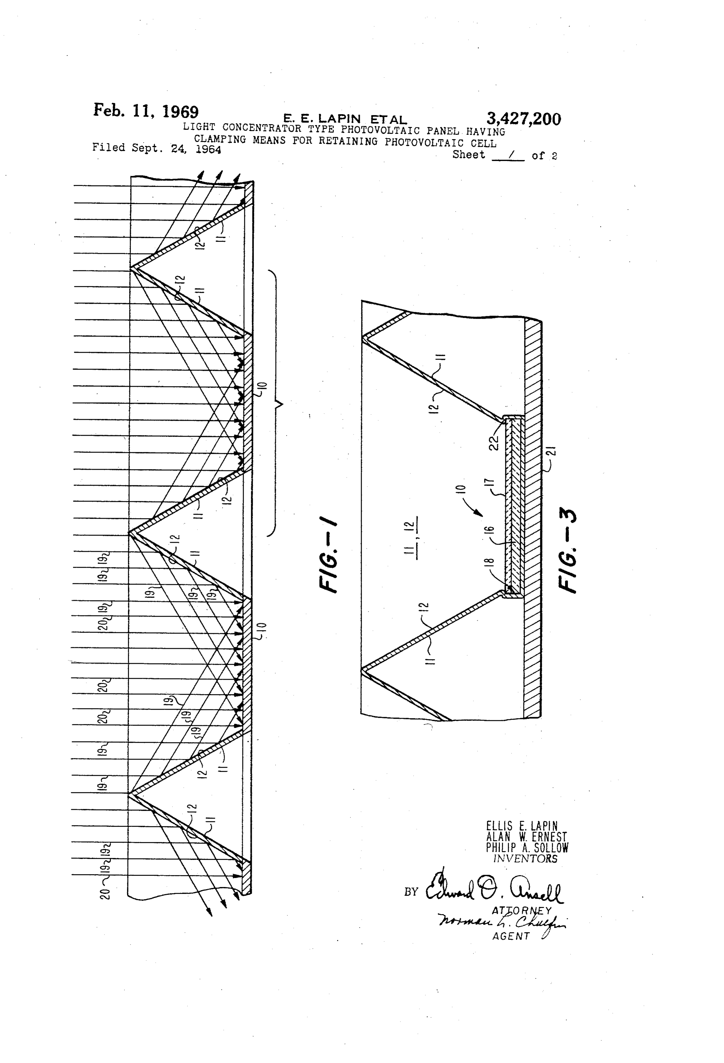
This disclosure concerns a photovoltaic device which 5 These and other objects and features of the invention comprises a plurality of photovoltaic modules, each in will become clearer from the following description and cluding a Solar cell having its own individual reflecting the appended claims taken together with the accompany surfaces. The cell of each module is disposed in a pocket ing illustrative drawings, in which: formed by the lower ends of the walls providing the FIGURE 1 is a sectional view, diagrammatic in form, reflecting Surfaces therefor. The walls include an inwardly 20 and showing the geometric arrangement of an array of crimped portion at the lower ends thereof which overlaps solar cells;
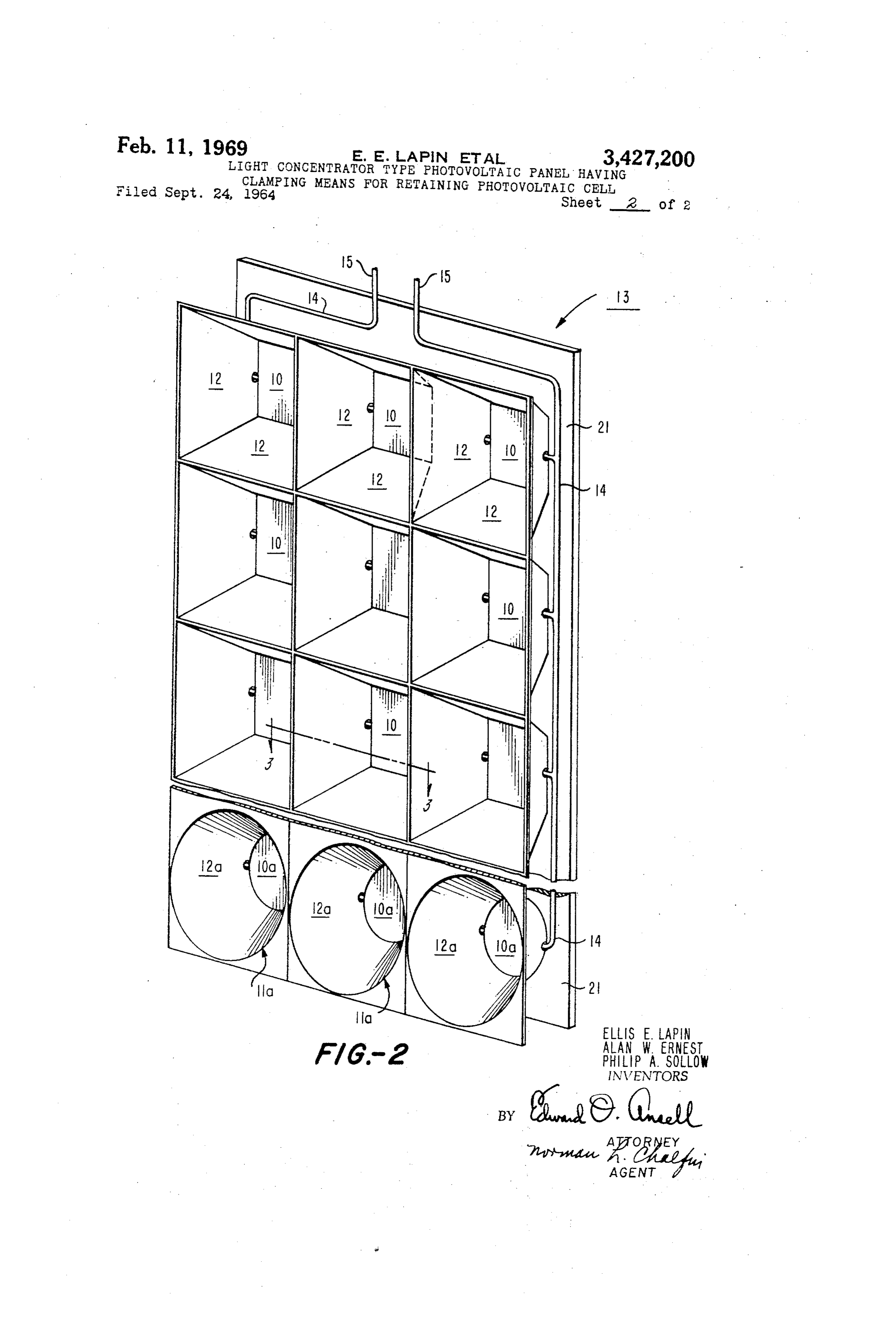
the upper edge of the cell so as to clamp and retain the FIGURE 2 is a perspective view drawn to a smaller cell in proper position in the pocket without requiring an scale than FIGURE 1 and showing a section of panel adhesive cement. formed by connecting together four of the arrays of mini 25 solar cells and reflectors shown in FIGURE 1; and
FIGURE 3 is a fragmentary enlarged sectional view
The present invention relates to photovoltaic devices showing the assembly of an individual solar cell in its and particularly to means for increasing the amount of reflector unit without the use of an adhesive cement be light received by the devices to obtain an increased out tween the elements of the cell.
put of electric current therefrom. 30 Referring now to FIGURE 1 in which a cross-section The use of photovoltaic devices to generate electrical of an array of cell modules is shown, the basic geometri power is well understood. Such devices responsive to the cal form of each solar cell module comprises the cell, radiant energy of the sun are known as solar cells and generally indicated at 10, with circumscribing Walls 11. are widely used on spacecraft in arrays comprising a In the embodiment being described, the cell 10 is shown multiplicity of cells formed into panels. 35 as square and the walls 11 of a width equal to the width Particularly in the case of spacecraft, such solar cell of the cell, and sloping outwardly at an angle of 60 installations should be as light as possible. The required from the plane of the cell face. The described construc electrical output should be obtained with a minimum tion results in a "module' or unit with four times the number of Solar cells, because such cells are very expen surface area of the face of the cell and a height from sive. Furthermore, such installations should be as free 40 the base less than the width of the walls. as possible from deterioration caused by conditions en It is to be understood that the details given are for countered in Space. Especially in cases where the space a particular embodiment only, since the shape of the cell craft may encounter the atmosphere of the earth, the may be of a different configuration, the angle of the Solar cell installation should cause minimum interference walls may be different, and their dimensions may have With the course calculated for the craft. The last men 45 different proportions within the scope of the invention. tioned requirement is particularly important, since most For example, the wall structures 11 shown as having Spacecraft are launched from the surface of the earth, a plane surface may have a conical configuration sur and at least initially in the flight, the solar cell arrays rounding the cell. In the particular case where the cell mounted on the craft must lie against the surface of the has a circular surface configuration, a conical outwardly Spacecraft. Erecting elements are provided to bring the 50 sloping wall would provide reflectivity to all parts of the Solar panels into operative position at a later time in cell surface.
the flight. The inwardly facing surfaces of the walls have a highly For maximum efficiency, solar cells have typically com reflective coating 12 thereon such that substantially all prised. Several elements cemented together. This cement 55 of the light indicated by lines 19 falling on the reflecting is Subject to deterioration, and the assembly of the ele Surfaces 12 of the walls 11 is reflected onto the exposed ments using the cement is time-consuming. Surface of the solar cell 10. The surface of cell 10 also It has been proposed that an entire panel of solar cells receives the light directly indicent thereto as indicated be surrounded with reflective walls. This would create by rays 20. Thus, light (rays 19, 20) falling on cell 10 an aerodynamically bulky structure for use in Spacecraft. due to the reflection from angled positions of walls 11 It is the general object of this invention to provide a 60 and from direct rays has an intensity at least 3 times as Solar cell assembly particularly adapted for use on space great as the direct rays 20 alone. The three fold ratio craft and free from the various disadvantages of the can be varied by changes in surface and shape of the reflective surfaces 12 of the walls 11 and their angles presently known structures.
It is another object of the invention to provide an im with respect to cell 10.
proved Solar cell module construction upon which a greater 65 13The individual modules are formed in panels, a section amount of light than has previously been possible may anceofofwhich is shown in FIGURE 2, having the appear a Waffle when the modules are of the size gen be concentrated onto each solar cell so as to obtain an increased output of electric current therefrom and thereby erally suitable for spacecraft, such as for instance, hav to produce a required output with fewer cells than needed 70 ingAllSolar
cells 10 about 2 cms, square.
the solar cells 10 are connected by wires 14 in present constructions, thus realizing a saving in weight in a series-parallel circuit arrangement that will provide of the modules.
the desired current and voltage at the wire terminals 15.
Page 4
As shown in FIGURE 3, each solar cell generally in is heavier, however, than panel elements 11. The resulting dicated at 10 comprises the cell 16 itself covered by a panel 13 was thin, light, and rigid, and under test pro glass cover 17 of an appropriate transmission character vided a large increase of electrical power as compared istic for the light rays 19 and 20. These components pref with the same cells tested without the reflector, panel erably are held together by suitably shaping the pocket elements 11 and the reflecting surfaces 12 thereon. 18 formed by the lower end portions of the walls 11 to An operative embodiment of the invention has been clamp cell 16 and cover glass 17 tightly together. In this described herein and shown by way of illustration in the connection, the mouth of the pocket 18 formed by the drawings. Another embodiment involving angled conical lower end portions of the walls 11 may be bounded by an reflective walls has been described and a fragment there inwardly crimped portion 22 formed in the lower end 0 of is shown in FIGURE 2 with conical walls being indi portions of the walls 11. The inwardly crimped wall por cated at 11a, the reflective inner surfaces 12a thereof sur tion 22 overlaps the upper edges of the cell 16 and the rounding a cell 10a which may have a circular shape. glass cover 17, with the inwardly crimped wall portion Operation of surfaces 12a to reflect light onto cell 10a 22 engaging the upper edge of the glass cover 17 so as to is the same as previously described for cell 10, and re clamp and retain the cell 16 and the glass cover 17 in 5 flective surfaces 12 of walls 11. proper position within the pocket 18 without requiring The embodiments described and shown herein should an adhesive cement. The usual shield to protect the cell not be construed as being necessarily limiting in scope, against corpuscular radiation is provided by the metal since various modifications may be made by those skilled of the reflective member. In current practice, the cell in the art within the spirit of the invention and the ambit components such as 16, 17 are secured together by an 20 of the appended claim.
organic cement, but this cement may be damaged by pro We claim:
longed exposure to the space environment. The parts 1. A photovoltaic panel comprising: a plurality of pho may, of course, be secured in place if preferred by the tovoltaic modules; each of said modules comprising a use of cement, as for instance, for flights of short dura photovoltaic cell for generating an electric current in re tion. 25 Sponse to light impinging thereon, thin walls surrounding The formed array of solar cells is mounted on a base said cell and inclined outwardly from the edges of said 21 which may be a thin plate or sheet of honeycomb ma cell, inwardly facing reflective surfaces on said walls ar terial, the bottoms of the pockets 18 for the solar cells ranged so as to direct the light incident upon said re 10 being secured to base 21 by any suitable bonding flective surfaces onto said cell to augment the light di method. One such method might be brazing or solder 30 rectly impinging on said cell, thereby to increase the ing. electrical current generated by said cell in response to Because of the honeycomb-like structure of the panel Said augmented light, the lower ends of said walls being 13 including the array of cells 10 and the base 21, it is shaped to provide a pocket, said cell being disposed in very light and rigid, and because of the greater output said pocket, and means overlapping the upper edge of of the individual solar cells 10 due to the greater amount 35 Said cell for clamping and retaining said cell in correct of light directed onto the cells by the described reflector position in said pocket; and adjacent modules of said plu surfaces 12 provided by the walls 11, the panel 13 of rality of modules being arranged in juxtaposed relation Solar cells 10 is at least no heavier than one constructed with respect to each other to define a uniform array of according to prior art practices. The construction of this said modules.
invention requires fewer solar cells for the same electri 40 References Cited cal output in a given radiation environment and will ob UNITED STATES PATENTS viously be lighter than a panel requiring a greater num 2,904,612 9/1959 Reginier ------------ 136-89 ber of cells as used in the prior art. 2,919,298 12/1959 Reginier et al. -------- 136-89 In a typical panel constructed according to this inven 45 3,018,313 1/1962 Gattone ------------ 136-89 tion, the reflector panel elements 11 were formed from 3,232,795 2/1966 Gillette et al. ------ 136-89 .001' brass sheet and the reflecting surfaces 12 were nickel plated thereon. The entire assembly of cell mod ALLEN B. CURTIS, Primary Examiner.
ules was secured to a relatively thin metal base 21 which
Provenance
- Collection
- Cited prior art
- Original PDF
- patentimages.storage.googleapis.com →
- Filed
- 1964-09-24
- Pages
- 4
- Method
- pdftotext (the PDF's own text layer) + pdftoppm 300dpi page scans
- Source
- Google Patents bibliographic record
- Granted
- 1969-02-11
- Inventors
- Ellis E Lapin; Alan W Ernest; Philip A Sollow; Aerojet General Corp
- Transcribed from
- patentimages.storage.googleapis.com →