patent · US5649517
Variable oxygen/nitrogen enriched intake air system for internal combustion engine applications
22 July 1997
Page 1 — bibliographic record
United States Patent 19 11 Patent Number: 5,649517 Poola et al. 45 Date of Patent: Jul. 22, 1997 54, WARIABLE OXYGEN/NITROGENENRICHED Attorney, Agent, or Firm-Mason, Kolehmainen, Rathburn INTAKE AIR SYSTEM FOR INTERNAL & Wyss
COMBUSTON ENGINE APPLICATIONS
75 Inventors: Ramesh B. Poola, Woodridge;
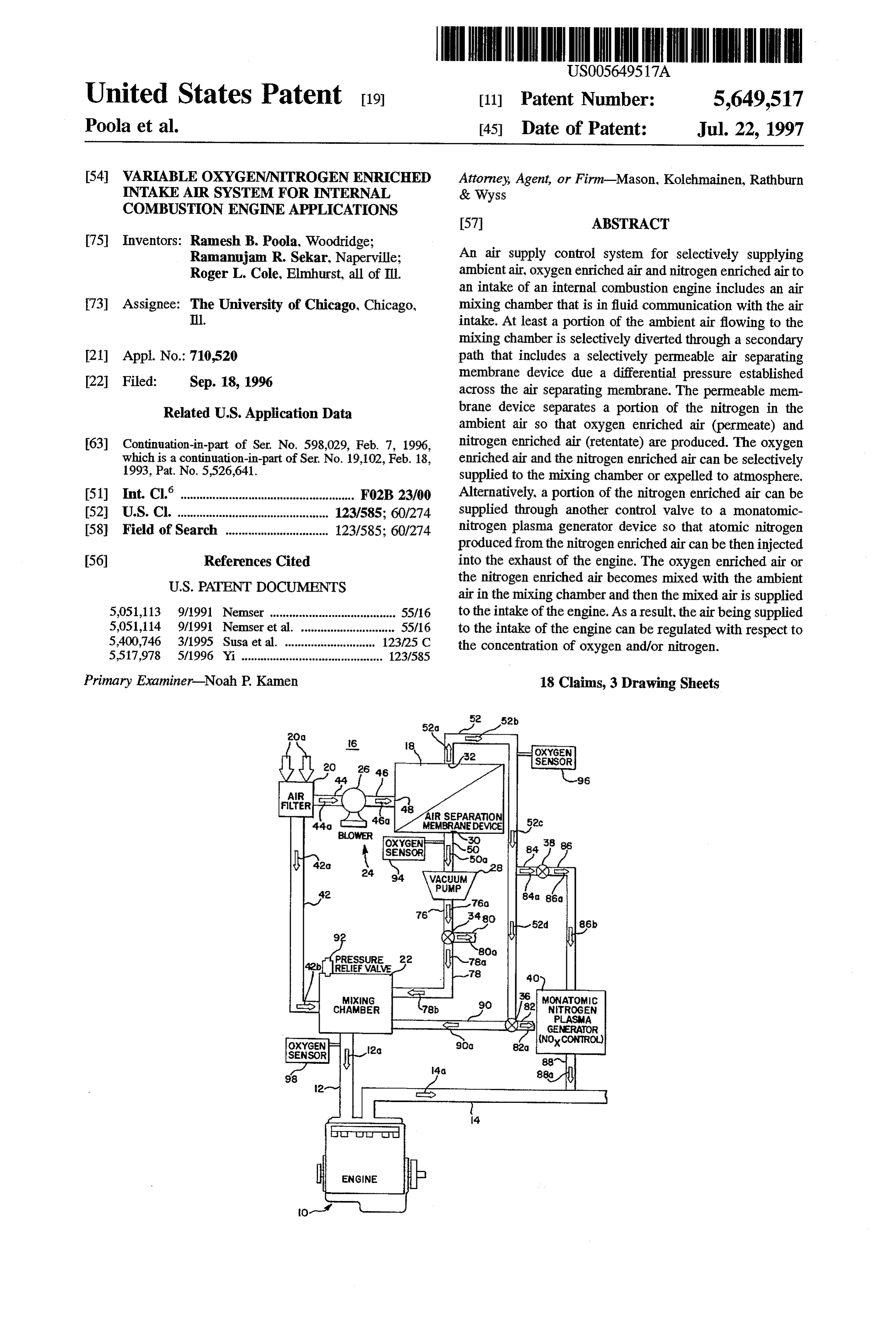
Ramanujam R. Sekar, Naperville; An air supply control system for selectively supplying Roger L. Cole, Elmhurst, all of Ill. ambient air, oxygen enriched air and nitrogen enriched air to an intake of an internal combustion engine includes an air 73) Assignee: The University of Chicago, Chicago, mixing chamber that is in fluid communication with the air Ill. intake. At least a portion of the ambient air flowing to the mixing chamber is selectively diverted through a secondary 21 Appl. No.:710,520 path that includes a selectively permeable air separating 22 Filed: Sep. 18, 1996 membrane device due a differential pressure established across the air separating membrane. The permeable mem
Related U.S. Application Data brane device separates a portion of the nitrogen in the ambient air so that oxygen enriched air (permeate) and 63) Continuation-in-part of Ser. No. 598,029, Feb. 7, 1996, nitrogen enriched air (retentate) are produced. The oxygen which is a continuation-in-part of Ser. No. 19,102, Feb. 18, enriched air and the nitrogen enriched air can be selectively 1993, Pat. No. 5,526,641. supplied to the mixing chamber or expelled to atmosphere. (51] Int. Claim. F02B 23/00 Alternatively, a portion of the nitrogen enriched air can be 52 U.S. Cl. ............................................ 123/585; 60/274 supplied through another control valve to a monatomic 58) Field of Search ............................. 123/585; 60/274 nitrogen plasma generator device so that atomic nitrogen produced from the nitrogen enriched air can be then injected 56) References Cited into the exhaust of the engine. The oxygen enriched air or
air in the mixing chamber and then the mixed air is supplied 5,051,113 9/1991 Nemser ....... ... 55/16 to the intake of the engine. As a result, the air being supplied 5,051,114 9/1991 Nemser et al. ........ 55/16 to the intake of the engine can be regulated with respect to 5,400,746 3/1995 Susa et al. ... ... 123/25 C the concentration of oxygen and/or nitrogen. 5,517,978 5/1996 Yi ......................................... 123/585
Primary Examiner-Noah P. Kamen 18 Claims, 3 Drawing Sheets
OXYGEN
OXYGEN
SENSOR
Page 2
Drawing sheet — no readable text.
Page 3
Drawing sheet — no readable text.
Page 4
Drawing sheet — no readable text.
Page 5
WARIABLE OXYGEN/NITROGEN ENRCHED exhaust pipes, electrically heated catalysts, exhaust-gas INTAKE AIR SYSTEM FOR INTERNAL burners, exhaust-gas igniters, and insulated converters (with COMBUSTION ENGINE APPLICATIONS vacuum or refractory material); (2) placement of the con verter closer to the exhaust manifold; and (3) management
CROSS REFERENCE TO RELATED of the interaction between the hydrocarbons and the catalyst, APPLICATION using hydrocarbon adsorbent or traps in the exhaust. This application is a continuation-in-part application of However, durability, fuel penalty, additional capital costs, unwanted heatin the engine compartment, and the complex
1996, which in turn is a continuation-in-part application of An alternative to such after-treatment methods is to con
1993, now U.S. Pat. No. 5,526,641 both of which prior combustion). One type of in-cylinder emission control is to applications are assigned to the same assignee as the introduce oxygen enriched air instead of ambient air to the assignee of this application. air intake of the engine. Use of such oxygen enriched air can CONTRACTUAL ORIGIN OF THE INVENTION 5 potentially decrease CO and HC emissions from a spark ignition engine, even during start-up and warming up
The United States Government has rights in this invention periods, because oxygen enrichment of the intake air pursuant to Contract No. W-31-109-ENG-38 between the decreases the emissions from the engine rapidly (even when United States Government and Argonne National Labora the engine is cold). In fact, it helps to minimize the catalytic tory. 20 converter limitations during the cold phase operation of the engine and should improve catalytic converter efficiency.
BACKGROUND OF THE INVENTION This method has the advantage offewer add-on components, 1. Field of the Invention of lesser mechanical complexities, of not altering the fuel economy
This invention relates to a method and apparatus for 25 (the air intake of the engine, and of an easier to modify system decreasing undesirable emissions in the exhaust of an inter system). system is easier to modify than the exhaust nal combustion engine, and more particularly, to a new and improved method and apparatus for selectively introducing Even though the oxygen enrichment of the intake air in spark ignition engine powered vehicles results in the low controlled quantities of oxygen and/or nitrogen enriched air ering into the intake of an internal combustion engine to thereby 30 of cold-phase HC and CO emissions in the exhaust of decrease the undesirable emissions that are present in the the vehicle, it tends to result in an increase in NO in the exhaust due to higher combustion temperatures. To some exhaust of the internal combustion engine. extent, the increase in NO in the emissions can be offset by 2. Background of the Invention NO control technologies that can remove nitrogen oxides Compression ignition (diesel) engines typically have high from the emissions. These technologies include lean NO exhaust emissions, such as particulates, visible Smoke, and 35 catalysts and the injection into the exhaust gases of oxides of nitrogen (NO). Environmental Protection Agency monatomic-nitrogen induced by a pulse arc (see, for (EPA) emissions standards require simultaneous reduction example, U.S. Pat. No. 5,526,641 that is assigned to the of NOx and particulate emissions to very low levels. This same assignee of record as the present application). tends to be difficult to achieve because of the inherent In the case of both diesel and spark ignition engines, tradeoffs between lowering both particulates and NOx emis exhaust gas recirculation (EGR) systems have been used as sions from a diesel engine. While it is possible in a diesel one method of decreasing NOx emissions. When the gases engine to reduce particulate emissions and to improve power from the EGR system are about 50% of the intake air, density performance by using oxygen enriched intake air, oxygen concentration is decreased from about 21% to about such oxygen enriched intake air tends to also increase the 14%. The decrease of NO by the use of EGR systems tends amount of NO in the exhaust being emitted from the diesel 45 to vary depending on the rate, temperature and water content engine. of the EGR gases, injection timing, and air-fuel ratio of the The type and amount of emissions in the exhaust of a intake to the engine. However, there are limits as to the sparkignition engine also is of concern. In order to meet the amount of exhaust gases that can be reintroduced into the California Air Resources Board (CARB), Low Emission engine before power output and fuel economy are adversely Vehicle (LEV) and Ultra Low Emission Vehicle (ULEV) 50 affected. Suchreintroduction of exhaust gases can also cause standards, substantial reductions are required for carbon wear problems and oil contamination, particularly in the monoxide (CO) and hydrocarbon (HC) emissions from a case of diesel engines where the recirculated gases include sparkignition engine during the cold phase of the federal test soot particles. The results obtained by using an EGR system procedure cycle. Similarly, many light-duty passenger cars are considered similar to the dilution of intake air with inert are required to decrease these emissions to comply with 55 gases such as nitrogen because in both cases the intake United States EPA's Tier-II (year 2004) standards. This oxygen concentration is decreased and the heat capacity of growing concern over start-up/cold-phase emissions has led the intake air is increased. While the benefits of using EGR to various attempts to develop new emissions treatment systems and nitrogen enriched air in the intake air of an techniques that decrease the HC and CO levels in the engine to lower the NOx emissions are similar, the advan exhaust emissions. 60 tages of using nitrogen enriched air over recirculated gases Attempts have been made by others to decrease cold from an EGR system are (i) the elimination of unwanted phase (i.e., the first 505 seconds of federal test procedure exhaust species (such as soot particles) being introduced into driving cycle, as specified in the Code of Federal the engines intake, (ii) the elimination of heat exchangers to Regulations, Title 40, Part 86, Subpart 8, revised 1993) cool and control the temperature and water content of the emissions by after-treatment methods. These methods can be 65 exhaust gases to be recirculated, and (iii) the elimination of grouped as follows: (1) thermal management of the catalytic poor utilization of intake air (higher displacement of intake converter, including low-mass manifolds, double-walled air).
Page 6
Notwithstanding the advantages of introducing oxygen permeable membrane device due to a pressure differential enriched air and/or nitrogen enriched air into the intake of an established across the membrane device. This pressure dif engine, the lack of an economical source of on-line oxygen ferential can be established by a blower at the input of the and nitrogen has made it difficult to provide a practical membrane device and a vacuum pump at the output of the application of the concept of providing oxygen and nitrogen membrane device. Alternatively, the differential pressure is enriched air to the air intake of the engine during various established across the membrane device when a compressor phases or time periods of operation of the engine. Relatively is used to supply compressed air to the input side of the compact oxygen enrichment devices, such as selectively membrane device.
permeable membranes, have been used to provide oxygen As the airflows through the permeable membrane device, enriched air to the air intake of an internal combustion 10 a portion of the nitrogen in the ambient air is separated from engine (see U.S. Pat. No. 5,526,641 and U.S. patent appli the air so that oxygen enriched air (permeate) and nitrogen cation Ser, No. 08/598,029, filed on Feb. 7, 1996, both of enriched air (retentate) are produced. The oxygen enriched which are assigned to the same assignee of record as the air can be selectively supplied through a control valve to the present application). Any such system requires a relatively mixing chamber or expelled to atmosphere. The nitrogen simple, compact mechanical system driven by the engine 15 enriched air similarly can be supplied through a control itself that will economically extract oxygen and nitrogen valve to the mixing chamber or expelled to atmosphere. from the ambient air and provide oxygen enriched and/or Alternatively, a portion of the nitrogen enriched air can be nitrogen enriched air to the air intake of the engine during supplied through another control valve to a monatomic particular phases or time periods of operation of the engine. nitrogen plasma generator or NO control device that forms Accordingly, it is an object of the present invention to 20 atomic nitrogen from the nitrogen enriched air which atomic provide a new and improved method and apparatus for nitrogen is then injected into the exhaust of the engine to decreasing particulate, HC, CO and NOx emissions in the chemically reduce some of the NO within the exhaust gases exhaust of an internal combustion engine by selectively being emitted by the engine. The oxygen enriched air, the introducing oxygen enriched and/or nitrogen enriched air nitrogen enriched air, or ambient air or combinations thereof into the air intake of the engine vehicle during selected 25 supplied to the mixing chamber become mixed within the periods or phases of operation of the engine. mixing chamber and then the mixed air is supplied to the It is another object of the present invention to provide a intake intake of the engine. As a result, the air being supplied to the of the engine can be regulated with respect to the new and improved method and apparatus for introducing concentration of oxygen and/or nitrogen. oxygen enriched and/or nitrogen enriched air into the air 30 intake of an internal combustion engine by diverting at least In another embodiment of the present invention, the air a portion of the intake air through a selectively permeable supply control system of the present invention enables membrane so that oxygen enriched and/or nitrogen enriched ambient air and nitrogen enriched air to be combined and air can be supplied to the engine intake manifold for selected supplied to the intake of a diesel type engine that includes a turbocharger. Pressurized ambient air is supplied by a tur periods of time during the operation of the engine and 35 bocompressor nitrogen enriched air can be supplied to a monatomic operated by the turbocharger. A portion of the nitrogen plasma generator that enables the chemical reduc pressurized ambient airflows to a mixing chamber. Another tion of NO in the exhaust of the engine. portion of the pressurized ambient air flows through a It is yet another object of the present invention to provide secondary path that includes a selectively permeable air a new and improved method and apparatus for introducing 40 established across the device separating membrane due to a pressure differential membrane device.
oxygen enriched and/or nitrogen enriched air into the air As the airflows through the permeable membrane device, intake of an internal combustion engine by diverting at least a portion a portion of the intake air through a selectively permeable the air soofthat the nitrogen in the ambient air is separated from oxygen enriched air (permeate) and nitrogen membrane so that ambient air, oxygen enriched air and/or enriched air (retentate) are produced. The oxygen enriched nitrogen enriched air can be selectively supplied to a mixing 45 is vented to atmosphere.
chamber and then from the mixing chamber to the engine air supplied through a control
The nitrogen enriched air can be valve to the mixing chamber or intake manifold during selected periods of time of operation expelled to atmosphere. Alternatively, a portion of the of the engine. nitrogen enriched air can be supplied through another con SUMMARY OF THE INVENTION trol valve to a monatomic-nitrogen plasma generator or NO 50 control device. The nitrogen enriched air and ambient air
In accordance with these and many other objects of the Supplied to the mixing chamber become mixed within the present invention, an air intake system for an internal mixing chamber and then the mixed air is supplied to the combustion engine embodying the present invention intake of the engine. As a result, the concentration of includes an air supply control system that enables ambient nitrogen in the air being supplied to the intake of the engine air, oxygen enriched air and/or nitrogen enriched air or a 55 can be regulated.
combination of each to be supplied to the intake of the BRIEF DESCRIPTION OF THE DRAWTNGS engine. During normal operation of the engine, ambient or atmospheric air from an air intake device flows to a mixing These and many other objects and advantages of the chamber and from the mixing chamber into an intake present invention will become readily apparent from con manifold of the engine. In order to decrease the amount of sideration of the following detailed description of the undesirable emissions in the exhaust gases produced by the embodiment of the invention shown in the accompanying engine during particular phases of the operation of the drawing wherein:
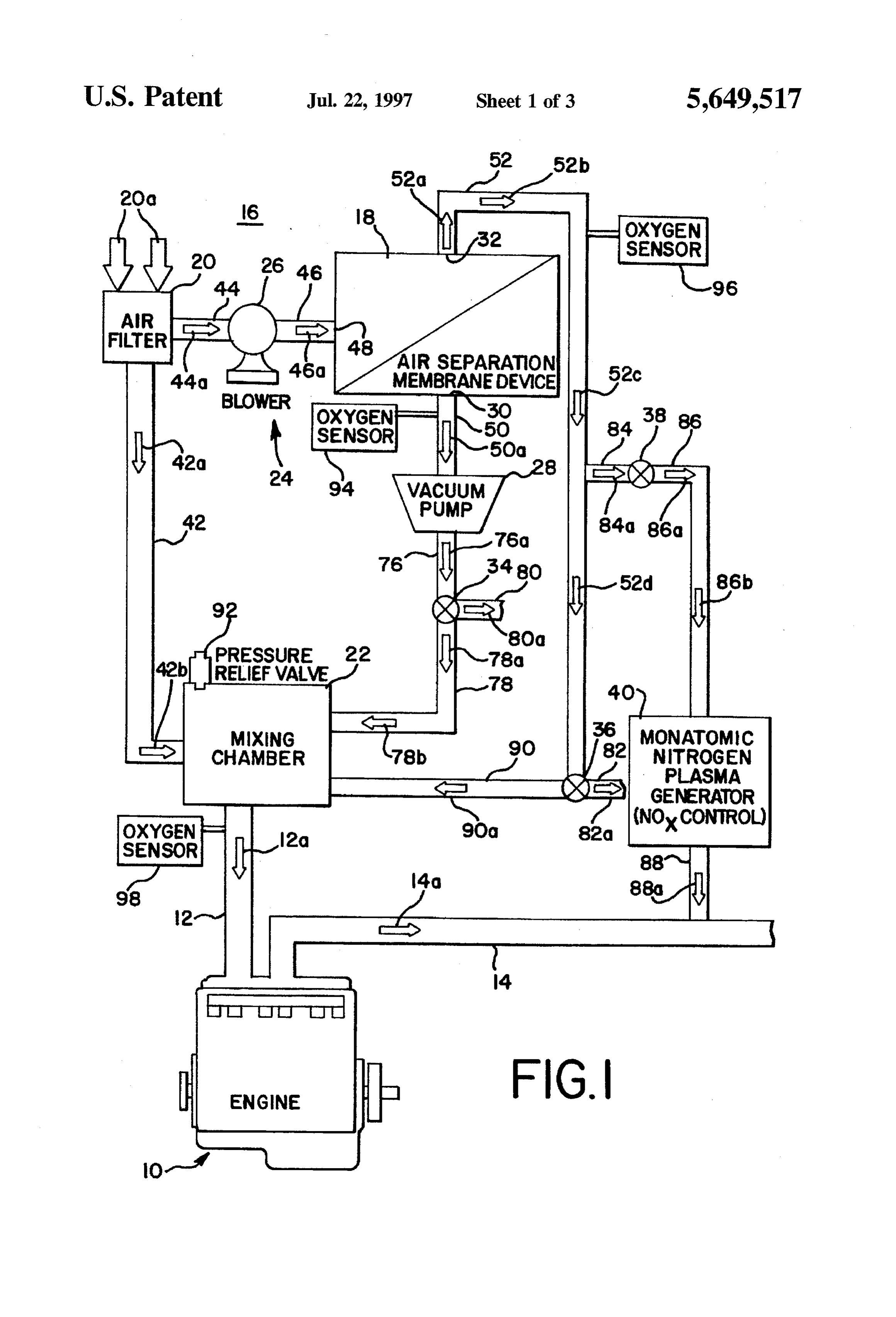
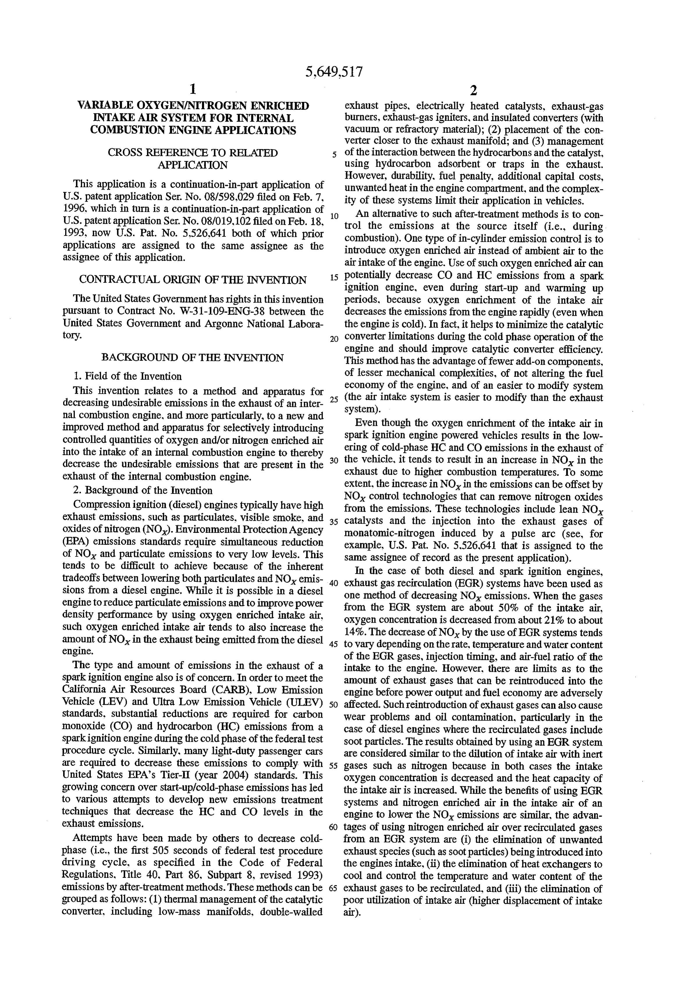
engine, at least a portion of the ambient airflowing from the FIG. 1 is a diagrammatic illustration of an internal com air intake device is diverted so that the diverted air flows bustion engine with an air intake control system which through a secondary path that includes a selectively perme 65 Supplies oxygen enriched and/or nitrogen enriched air to the able air separating membrane device. The ambient air being intake of the engine and which embodies the present inven diverted through the secondary path flows through the tion;
Page 7
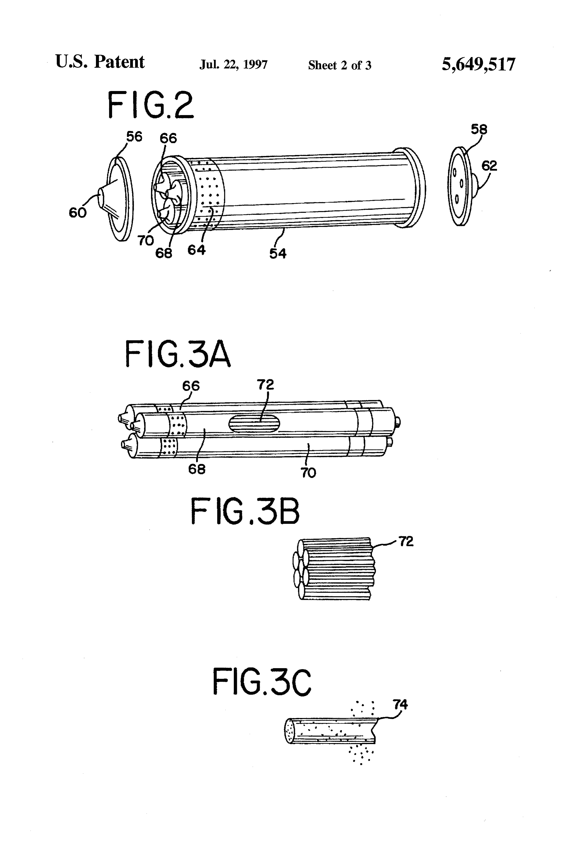
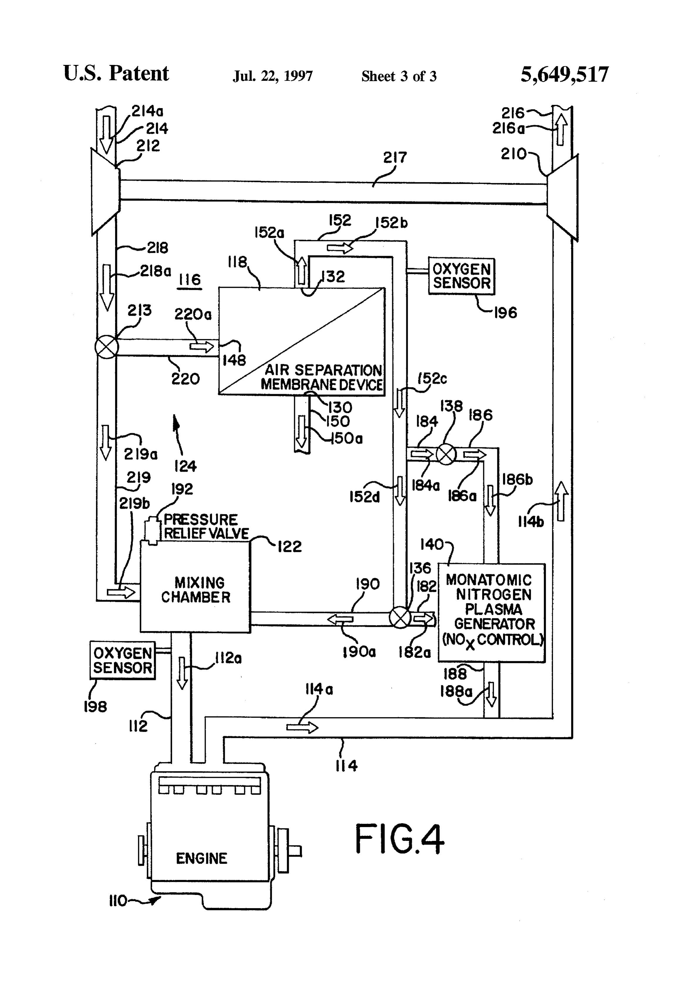
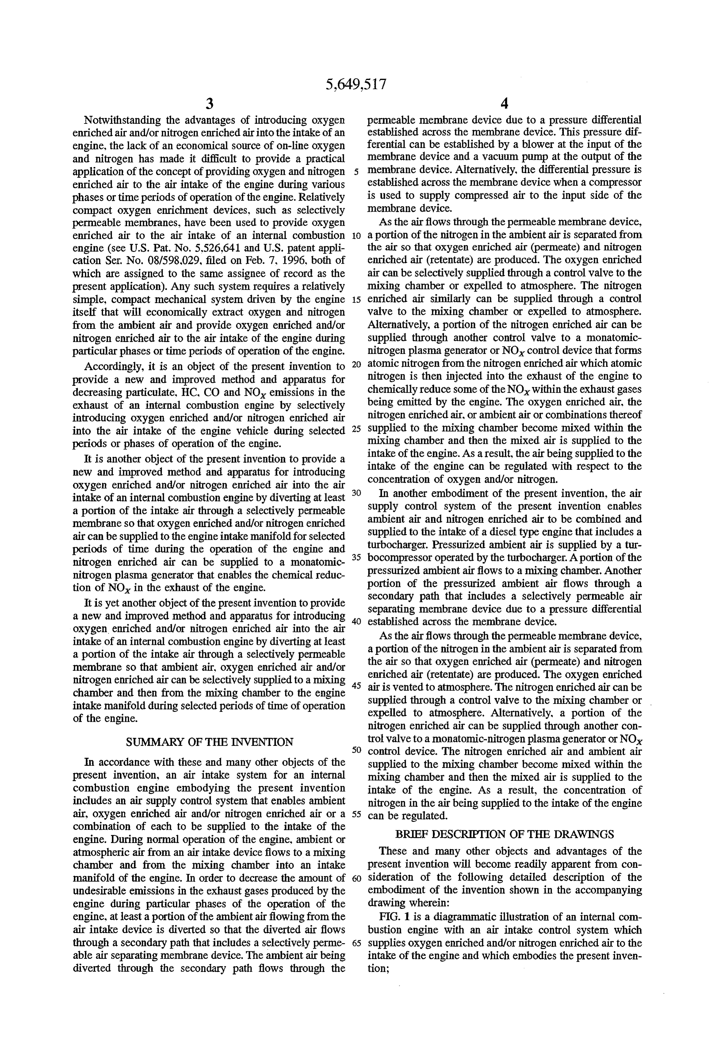
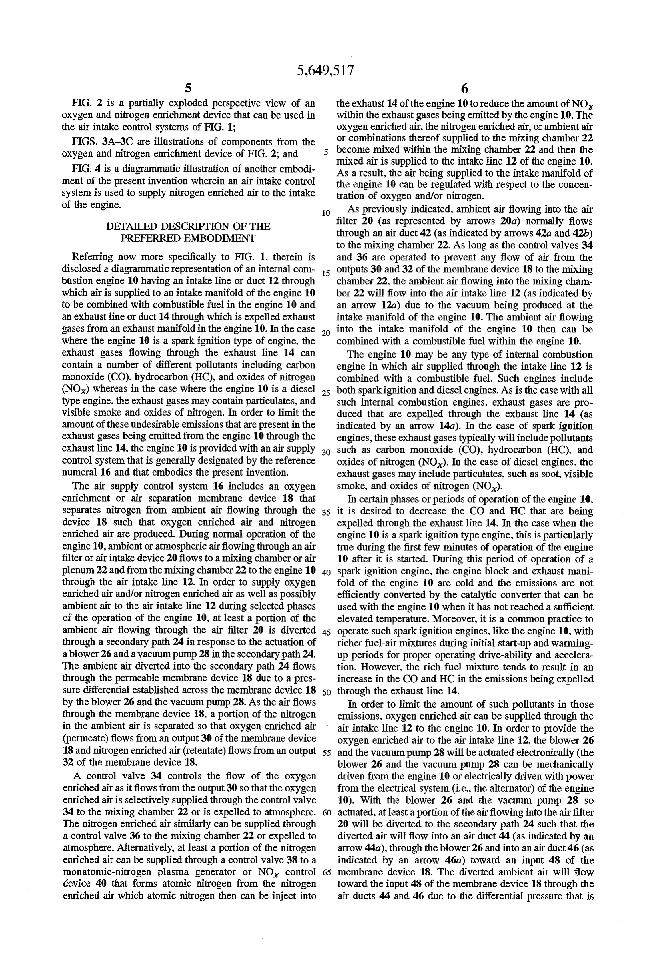
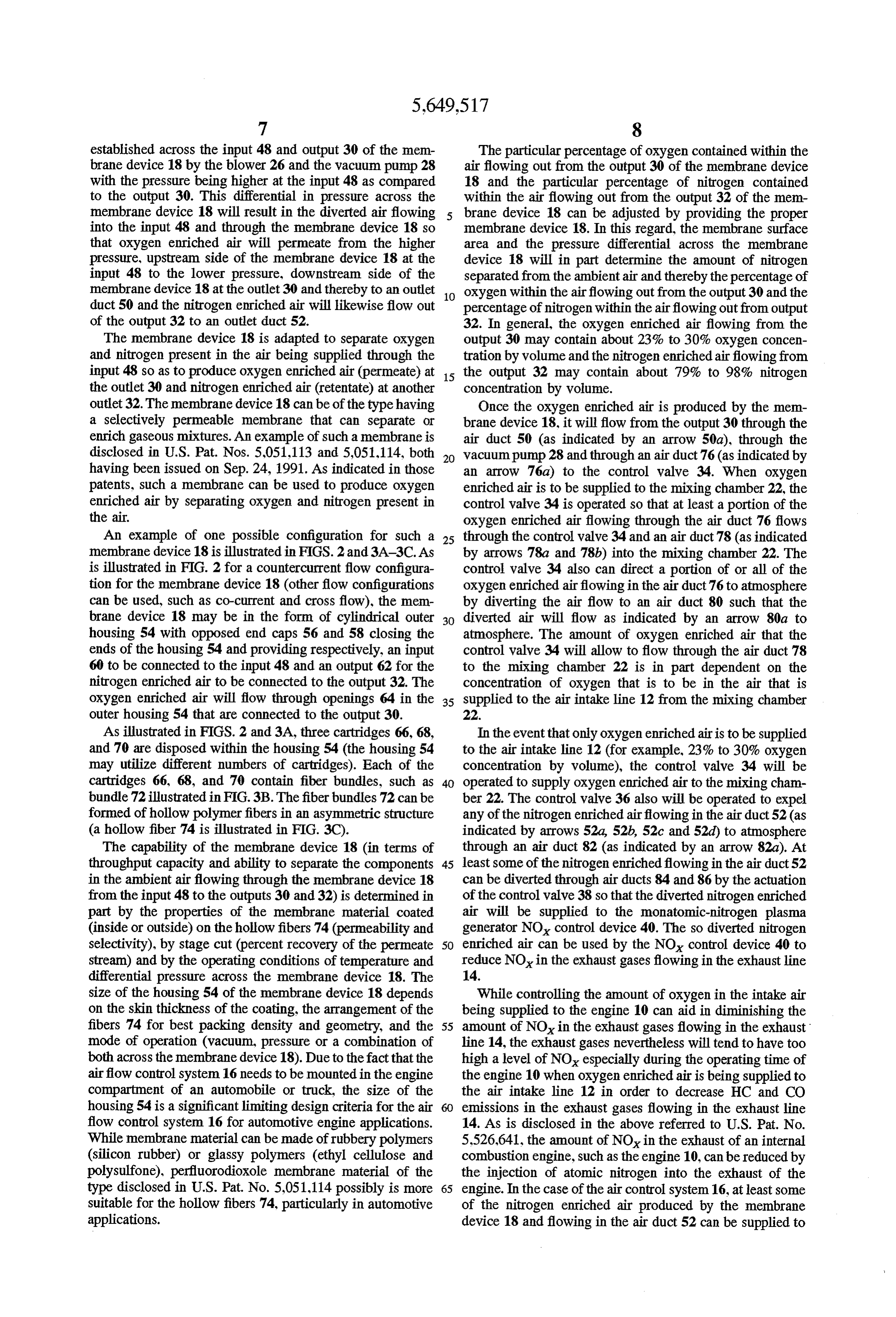
FIG. 2 is a partially exploded perspective view of an the exhaust 14 of the engine 10 to reduce the amount of NO Oxygen and nitrogen enrichment device that can be used in within the exhaust gases being emitted by the engine 10. The the air intake control systems of FIG. 1; oxygen enriched air, the nitrogen enriched air, or ambient air FIGS. 3A-3C are illustrations of components from the or combinations thereof supplied to the mixing chamber 22 Oxygen and nitrogen enrichment device of FIG. 2; and become mixed within the mixing chamber 22 and then the FIG. 4 is a diagrammatic illustration of another embodi As mixed air is supplied to the intake line 12 of the engine 10. a result, the air being supplied to the intake manifold of ment of the present invention wherein an air intake control the engine 10 can be regulated with respect to the concen system is used to supply nitrogen enriched air to the intake tration of oxygen and/or nitrogen.
of the engine. O As previously indicated, ambient air flowing into the air DETALED DESCRIPTION OF THE filter 20 (as represented by arrows 20a) normally flows PREFERRED EMBODIMENT through an air duct 42 (as indicated by arrows 42a and 42b) to the mixing chamber 22. As long as the control valves 34
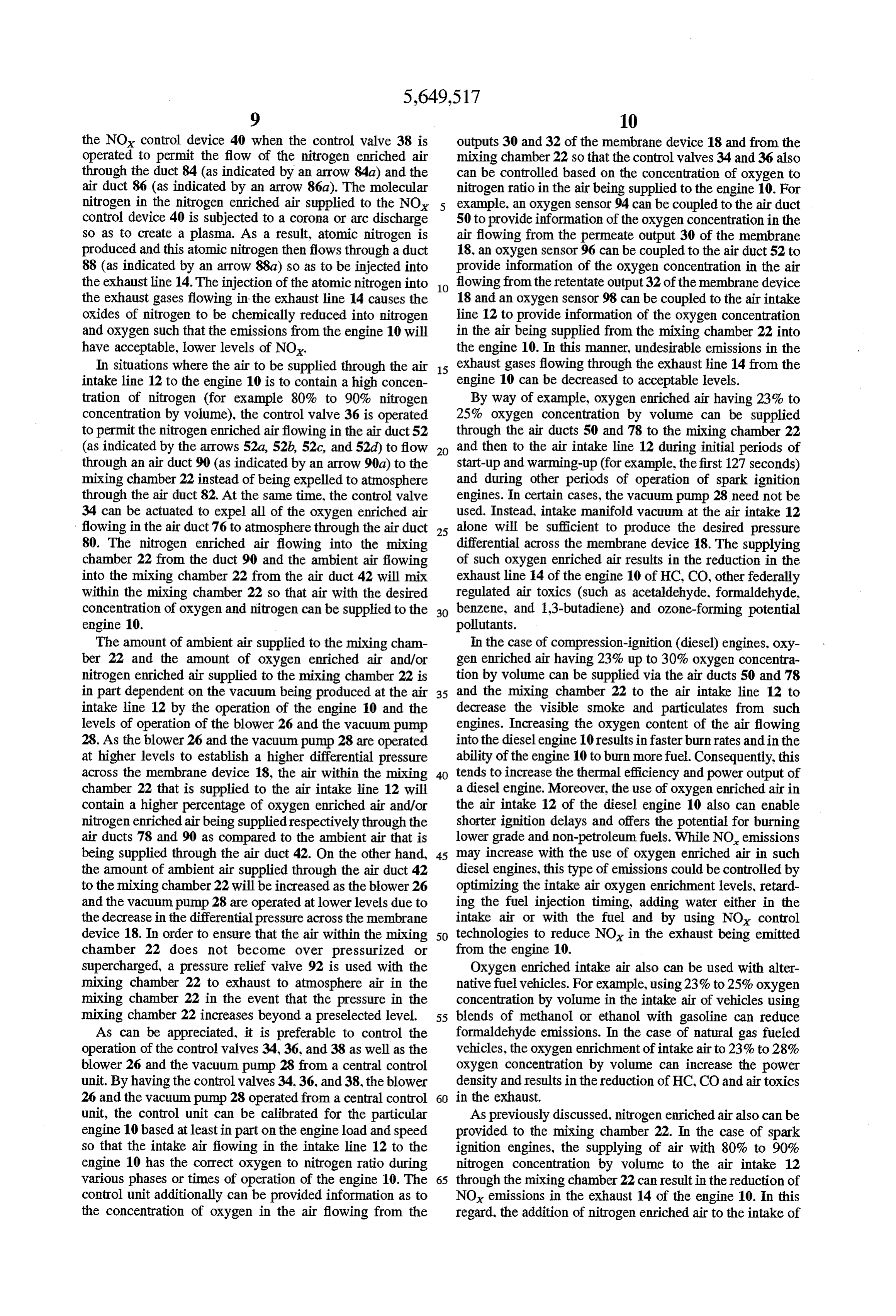
Referring now more specifically to FIG. 1, therein is and 36 are operated to prevent any flow of air from the disclosed a diagrammatic representation of an internal com 5 outputs 30 and 32 of the membrane device 18 to the mixing bustion engine 10 having an intake line or duct 12 through chamber 22, the ambient air flowing into the mixing cham which air is supplied to an intake manifold of the engine 10 ber 22 will flow into the air intake line 12 (as indicated by to be combined with combustible fuel in the engine 10 and an arrow 12a) due to the vacuum being produced at the an exhaustline or duct 14 through which is expelled exhaust intake manifold of the engine 10. The ambient air flowing gases from an exhaust manifold in the engine 10. In the case 20 into the intake manifold of the engine 10 then can be where the engine 10 is a spark ignition type of engine, the combined with a combustible fuel within the engine 10. exhaust gases flowing through the exhaust line 14 can The engine 10 may be any type of internal combustion contain a number of different pollutants including carbon engine in which air supplied through the intake line 12 is monoxide (CO), hydrocarbon (HC), and oxides of nitrogen combined with a combustible fuel. Such engines include (NO) whereas in the case where the engine 10 is a diesel 25 both sparkignition and diesel engines. As is the case with all type engine, the exhaust gases may contain particulates, and such internal combustion engines, exhaust gases are pro visible Smoke and oxides of nitrogen. In order to limit the duced that are expelled through the exhaust line 14 (as amount of these undesirable emissions that are present in the indicated by an arrow 14a). In the case of spark ignition exhaust gases being emitted from the engine 10 through the engines, these exhaust gases typically will include pollutants exhaustline 14, the engine 10 is provided with an air supply 30 such as carbon monoxide (CO), hydrocarbon (HC), and control system that is generally designated by the reference oxides of nitrogen (NO). In the case of diesel engines, the numeral 16 and that embodies the present invention. exhaust gases may include particulates, such as soot, visible The air supply control system 16 includes an oxygen Smoke, and oxides of nitrogen (NO).
enrichment or air separation membrane device 18 that In certain phases or periods of operation of the engine 10, separates nitrogen from ambient air flowing through the 35 it is desired to decrease the CO and HC that are being device 18 such that oxygen enriched air and nitrogen expelled through the exhaust line 14. In the case when the enriched air are produced. During normal operation of the engine 10 is a sparkignition type engine, this is particularly engine 10, ambient or atmospheric airflowing through an air true during the first few minutes of operation of the engine filter or air intake device 20 flows to a mixing chamber or air 10 after it is started. During this period of operation of a plenum 22 and from the mixing chamber 22 to the engine 10 40 spark ignition engine, the engine block and exhaust mani through the air intake line 12. In order to supply oxygen fold of the engine 10 are cold and the emissions are not enriched air and/or nitrogen enriched air as well as possibly efficiently converted by the catalytic converter that can be ambient air to the air intake line 12 during selected phases used with the engine 10 when it has not reached a sufficient of the operation of the engine 10, at least a portion of the elevated temperature. Moreover, it is a common practice to ambient air flowing through the air filter 20 is diverted 45 operate such sparkignition engines, like the engine 10, with through a secondary path 24 in response to the actuation of richer fuel-air mixtures during initial start-up and warming a blower 26 and a vacuum pump 28 in the secondary path 24. up periods for proper operating drive-ability and accelera The ambient air diverted into the secondary path 24 flows tion. However, the rich fuel mixture tends to result in an through the permeable membrane device 18 due to a pres increase in the CO and HC in the emissions being expelled Sure differential established across the membrane device 18 50 through the exhaust line 14.
by the blower 26 and the vacuum pump 28. As the airflows In order to limit the amount of such pollutants in those through the membrane device 18, a portion of the nitrogen emissions, oxygen enriched air can be supplied through the in the ambient air is separated so that oxygen enriched air air intake line 12 to the engine 10. In order to provide the (permeate) flows from an output 30 of the membrane device oxygen enriched air to the air intake line 12, the blower 26 18 and nitrogen enriched air (retentate) flows from an output 55 and the vacuum pump 28 will be actuated electronically (the 32 of the membrane device 18. blower 26 and the vacuum pump 28 can be mechanically A control valve 34 controls the flow of the oxygen driven from the engine 10 or electrically driven with power enriched air as it flows from the output 30 so that the oxygen from the electrical system (i.e., the alternator) of the engine enriched air is selectively supplied through the control valve 10). With the blower 26 and the vacuum pump 28 so 34 to the mixing chamber 22 or is expelled to atmosphere. 60 actuated, at least a portion of the airflowing into the airfilter The nitrogen enriched air similarly can be supplied through 20 will be diverted to the secondary path 24 such that the a control valve 36 to the mixing chamber 22 or expelled to diverted air will flow into an air duct 44 (as indicated by an atmosphere. Alternatively, at least a portion of the nitrogen arrow 44a), through the blower 26 and into an air duct 46 (as enriched air can be supplied through a control valve 38 to a indicated by an arrow 46a) toward an input 48 of the monatomic-nitrogen plasma generator or NO control 65 membrane device 18. The diverted ambient air will flow device 40 that forms atomic nitrogen from the nitrogen toward the input 48 of the membrane device 18 through the enriched air which atomic nitrogen then can be inject into air ducts 44 and 46 due to the differential pressure that is
Page 8
established across the input 48 and output 30 of the mem The particular percentage of oxygen contained within the brane device 18 by the blower 26 and the vacuum pump 28 air flowing out from the output 30 of the membrane device with the pressure being higher at the input 48 as compared 18 and the particular percentage of nitrogen contained to the output 30. This differential in pressure across the within the air flowing out from the output 32 of the mem membrane device 18 will result in the diverted air flowing brane device 18 can be adjusted by providing the proper into the input 48 and through the membrane device 18 so membrane device 18. In this regard, the membrane surface that oxygen enriched air will permeate from the higher area and the pressure differential across the membrane pressure, upstream side of the membrane device 18 at the device 18 will in part determine the amount of nitrogen input 48 to the lower pressure, downstream side of the separated from the ambient air and thereby the percentage of membrane device 18 at the outlet 30 and thereby to an outlet 10 oxygen within the airflowing out from the output 30 and the duct 50 and the nitrogen enriched air will likewise flow out percentage of nitrogen within the airflowing out from output of the output 32 to an outlet duct 52. 32. In general, the oxygen enriched air flowing from the The membrane device 18 is adapted to separate oxygen output 30 may contain about 23% to 30% oxygen concen and nitrogen present in the air being supplied through the tration by volume and the nitrogen enriched airflowing from input 48 so as to produce oxygen enriched air (permeate) at 15 the output 32 may contain about 79% to 98% nitrogen the outlet 30 and nitrogen enriched air (retentate) at another concentration by volume.
outlet 32. The membrane device 18 can be of the type having Once the oxygen enriched air is produced by the mem a selectively permeable membrane that can separate or brane device 18, it will flow from the output 30 through the enrich gaseous mixtures. An example of such a membrane is air duct 50 (as indicated by an arrow 50a), through the disclosed in U.S. Pat. Nos. 5,051.113 and 5,051.114, both 20 vacuum pump 28 and through an air duct 76 (as indicated by having been issued on Sep. 24, 1991. As indicated in those an arrow 76a) to the control valve 34. When oxygen patents, such a membrane can be used to produce oxygen enriched air is to be supplied to the mixing chamber 22, the enriched air by separating oxygen and nitrogen present in control valve 34 is operated so that at least a portion of the the air. oxygen enriched air flowing through the air duct 76 flows An example of one possible configuration for such a 25 through the control valve 34 and an air duct 78 (as indicated membrane device 18 is illustrated in FIGS. 2 and 3A-3C. As by arrows 78a and 78b) into the mixing chamber 22. The is illustrated in FIG. 2 for a countercurrent flow configura control valve 34 also can direct a portion of or all of the tion for the membrane device 18 (other flow configurations oxygen enriched airflowing in the air duct 76 to atmosphere can be used, such as co-current and cross flow), the mem by diverting the air flow to an air duct 80 such that the brane device 18 may be in the form of cylindrical outer 30 diverted air will flow as indicated by an arrow 80a to housing 54 with opposed end caps 56 and 58 closing the atmosphere. The amount of oxygen enriched air that the ends of the housing 54 and providing respectively, an input control valve 34 will allow to flow through the air duct 78 60 to be connected to the input 48 and an output 62 for the to the mixing chamber 22 is in part dependent on the nitrogen enriched air to be connected to the output 32. The concentration of oxygen that is to be in the air that is oxygen enriched air will flow through openings 64 in the 35 supplied to the air intake line 12 from the mixing chamber outer housing 54 that are connected to the output 30. 22.
As illustrated in FIGS. 2 and 3A, three cartridges 66, 68, In the event that only oxygen enriched air is to be supplied and 70 are disposed within the housing 54 (the housing 54 to the air intake line 12 (for example, 23% to 30% oxygen may utilize different numbers of cartridges). Each of the concentration by volume), the control valve 34 will be cartridges 66, 68, and 70 contain fiber bundles, such as 40 operated to supply oxygen enriched air to the mixing cham bundle 72 illustrated in FIG.3B. The fiberbundles 72 can be ber 22. The control valve 36 also will be operated to expel formed of hollow polymer fibers in an asymmetric structure any of the nitrogen enriched airflowing in the air duct 52 (as (a hollow fiber 74 is illustrated in FIG. 3C). indicated by arrows 52a, 52b, 52c and 52d) to atmosphere The capability of the membrane device 18 (in terms of through an air duct 82 (as indicated by an arrow 82a). At throughput capacity and ability to separate the components 45 least some of the nitrogen enriched flowing in the air ductS2 in the ambient airflowing through the membrane device 18 can be diverted through air ducts 84 and 86 by the actuation from the input 48 to the outputs 30 and 32) is determined in of the control valve 38 so that the diverted nitrogen enriched part by the properties of the membrane material coated air will be supplied to the monatomic-nitrogen plasma (inside or outside) on the hollow fibers 74 (permeability and generator NO control device 40. The so diverted nitrogen selectivity), by stage cut (percent recovery of the permeate 50 enriched air can be used by the NO control device 40 to stream) and by the operating conditions of temperature and reduce NO in the exhaust gases flowing in the exhaust line differential pressure across the membrane device 18. The 14.
size of the housing 54 of the membrane device 18 depends While controlling the amount of oxygen in the intake air on the skin thickness of the coating, the arrangement of the being supplied to the engine 10 can aid in diminishing the fibers 74 for best packing density and geometry, and the 55 amount of NO in the exhaust gases flowing in the exhaust mode of operation (vacuum, pressure or a combination of line 14, the exhaust gases nevertheless will tend to have too both across the membrane device 18). Due to the fact that the high a level of NOx especially during the operating time of airflow control system 16 needs to be mounted in the engine the engine 10 when oxygen enriched air is being supplied to compartment of an automobile or truck, the size of the the air intake line 12 in order to decrease HC and CO housing 54 is a significant limiting design criteria for the air emissions in the exhaust gases flowing in the exhaust line flow control system 16 for automotive engine applications. 14. As is disclosed in the above referred to U.S. Pat. No. While membrane material can be made of rubbery polymers 5,526,641, the amount of NO in the exhaust of an internal (silicon rubber) or glassy polymers (ethyl cellulose and combustion engine, such as the engine 10, can be reduced by polysulfone), perfluorodioxole membrane material of the the injection of atomic nitrogen into the exhaust of the type disclosed in U.S. Pat. No. 5,051.114 possibly is more 65 engine. In the case of the air control system 16, at least some suitable for the hollow fibers 74, particularly in automotive of the nitrogen enriched air produced by the membrane applications. device 18 and flowing in the air duct 52 can be supplied to
Page 9
the NO control device 40 when the control valve 38 is outputs 30 and 32 of the membrane device 18 and from the operated to permit the flow of the nitrogen enriched air mixing chamber 22 so that the control valves 34 and 36 also through the duct 84 (as indicated by an arrow 84a) and the can be controlled based on the concentration of oxygen to air duct 86 (as indicated by an arrow 86a). The molecular nitrogen ratio in the air being supplied to the engine 10. For nitrogen in the nitrogen enriched air supplied to the NO 5 example, an oxygen sensor 94 can be coupled to the air duct control device 40 is subjected to a corona or arc discharge 50 to provide information of the oxygen concentration in the so as to create a plasma. As a result, atomic nitrogen is air flowing from the permeate output 30 of the membrane produced and this atomic nitrogen then flows through a duct 18, an oxygen sensor 96 can be coupled to the air duct 52 to 88 (as indicated by an arrow 88a) so as to be injected into provide information of the oxygen concentration in the air the exhaustline 14. The injection of the atomic nitrogen into 10 flowing from the retentate output 32 of the membrane device the exhaust gases flowing in the exhaust line 14 causes the 18 and an oxygen sensor 98 can be coupled to the air intake oxides of nitrogen to be chemically reduced into nitrogen line 12 to provide information of the oxygen concentration and oxygen such that the emissions from the engine 10 will in the air being supplied from the mixing chamber 22 into have acceptable, lower levels of NO. the engine 10. In this manner, undesirable emissions in the In situations where the air to be supplied through the air 15 exhaust gases flowing through the exhaust line 14 from the intake line 12 to the engine 10 is to contain a high concen engine 10 can be decreased to acceptable levels. tration of nitrogen (for example 80% to 90% nitrogen By way of example, oxygen enriched air having 23% to concentration by volume), the control valve 36 is operated 25% oxygen concentration by volume can be supplied to permit the nitrogen enriched airflowing in the air duct 52 through the air ducts 50 and 78 to the mixing chamber 22 (as indicated by the arrows 52a, 52b, 52c, and 52d) to flow 20 and then to the air intake line 12 during initial periods of through an air duct 90 (as indicated by an arrow 90a) to the start-up and warming-up (for example, the first 127 seconds) mixing chamber 22 instead of being expelled to atmosphere and during other periods of operation of spark ignition through the air duct 82. At the same time, the control valve engines. In certain cases, the vacuum pump 28 need not be 34 can be actuated to expel all of the oxygen enriched air used. Instead, intake manifold vacuum at the air intake 12 flowing in the air duct 76 to atmosphere through the air duct 25 alone will be sufficient to produce the desired pressure 80. The nitrogen enriched air flowing into the mixing differential across the membrane device 18. The supplying chamber 22 from the duct 90 and the ambient air flowing of such oxygen enriched air results in the reduction in the into the mixing chamber 22 from the air duct 42 will mix exhaust line 14 of the engine 10 of HC, CO, other federally within the mixing chamber 22 so that air with the desired regulated air toxics (such as acetaldehyde, formaldehyde, concentration of oxygen and nitrogen can be supplied to the 30 benzene, and 1,3-butadiene) and ozone-forming potential engine 10. pollutants.
The amount of ambient air supplied to the mixing cham In the case of compression-ignition (diesel) engines, oxy ber 22 and the amount of oxygen enriched air and/or gen enriched air having 23% up to 30% oxygen concentra nitrogen enriched air supplied to the mixing chamber 22 is tion by volume can be supplied via the air ducts 50 and 78 in part dependent on the vacuum being produced at the air 35 and the mixing chamber 22 to the air intake line 12 to intake line 12 by the operation of the engine 10 and the decrease the visible smoke and particulates from such levels of operation of the blower 26 and the vacuum pump engines. Increasing the oxygen content of the air flowing 28. As the blower 26 and the vacuum pump 28 are operated into the diesel engine 10 results infasterburn rates and in the at higher levels to establish a higher differential pressure ability of the engine 10 to burn more fuel. Consequently, this across the membrane device 18, the air within the mixing 40 tends to increase the thermal efficiency and power output of chamber 22 that is supplied to the air intake line 12 will a diesel engine. Moreover, the use of oxygen enriched air in contain a higher percentage of oxygen enriched air and/or the air intake 12 of the diesel engine 10 also can enable nitrogen enriched air being supplied respectively through the shorter ignition delays and offers the potential for burning air ducts 78 and 90 as compared to the ambient air that is lower grade and non-petroleum fuels. While NO emissions being supplied through the air duct 42. On the other hand, 45 may increase with the use of oxygen enriched air in such the amount of ambient air supplied through the air duct 42 diesel engines, this type of emissions could be controlled by to the mixing chamber 22 will be increased as the blower 26 optimizing the intake air oxygen enrichment levels, retard and the vacuum pump 28 are operated at lower levels due to ing the fuel injection timing, adding water either in the the decrease in the differential pressure across the membrane intake air or with the fuel and by using NO control device 18. In order to ensure that the air within the mixing 50 technologies to reduce NO in the exhaust being emitted chamber 22 does not become over pressurized or from the engine 10.
supercharged, a pressure relief valve 92 is used with the Oxygen enriched intake air also can be used with alter mixing chamber 22 to exhaust to atmosphere air in the native fuel vehicles. For example, using 23% to 25% oxygen mixing chamber 22 in the event that the pressure in the concentration by volume in the intake air of vehicles using mixing chamber 22 increases beyond a preselected level. 55 blends of methanol or ethanol with gasoline can reduce As can be appreciated, it is preferable to control the formaldehyde emissions. In the case of natural gas fueled operation of the control valves 34, 36, and 38 as well as the vehicles, the oxygen enrichment of intake air to 23% to 28% blower 26 and the vacuum pump 28 from a central control oxygen concentration by volume can increase the power unit. By having the control valves 34, 36, and 38, the blower density and results in the reduction of HC, CO and air toxics 26 and the vacuum pump 28 operated from a central control 60 in the exhaust.
unit, the control unit can be calibrated for the particular As previously discussed, nitrogen enriched air also can be engine 10 based at least in part on the engine load and speed provided to the mixing chamber 22. In the case of spark so that the intake air flowing in the intake line 12 to the ignition engines, the supplying of air with 80% to 90% engine 10 has the correct oxygen to nitrogen ratio during nitrogen concentration by volume to the air intake 12 various phases or times of operation of the engine 10. The 65 through the mixing chamber 22 can result in the reduction of control unit additionally can be provided information as to NO emissions in the exhaust 14 of the engine 10. In this the concentration of oxygen in the air flowing from the regard, the addition of nitrogen enriched air to the intake of
Page 10
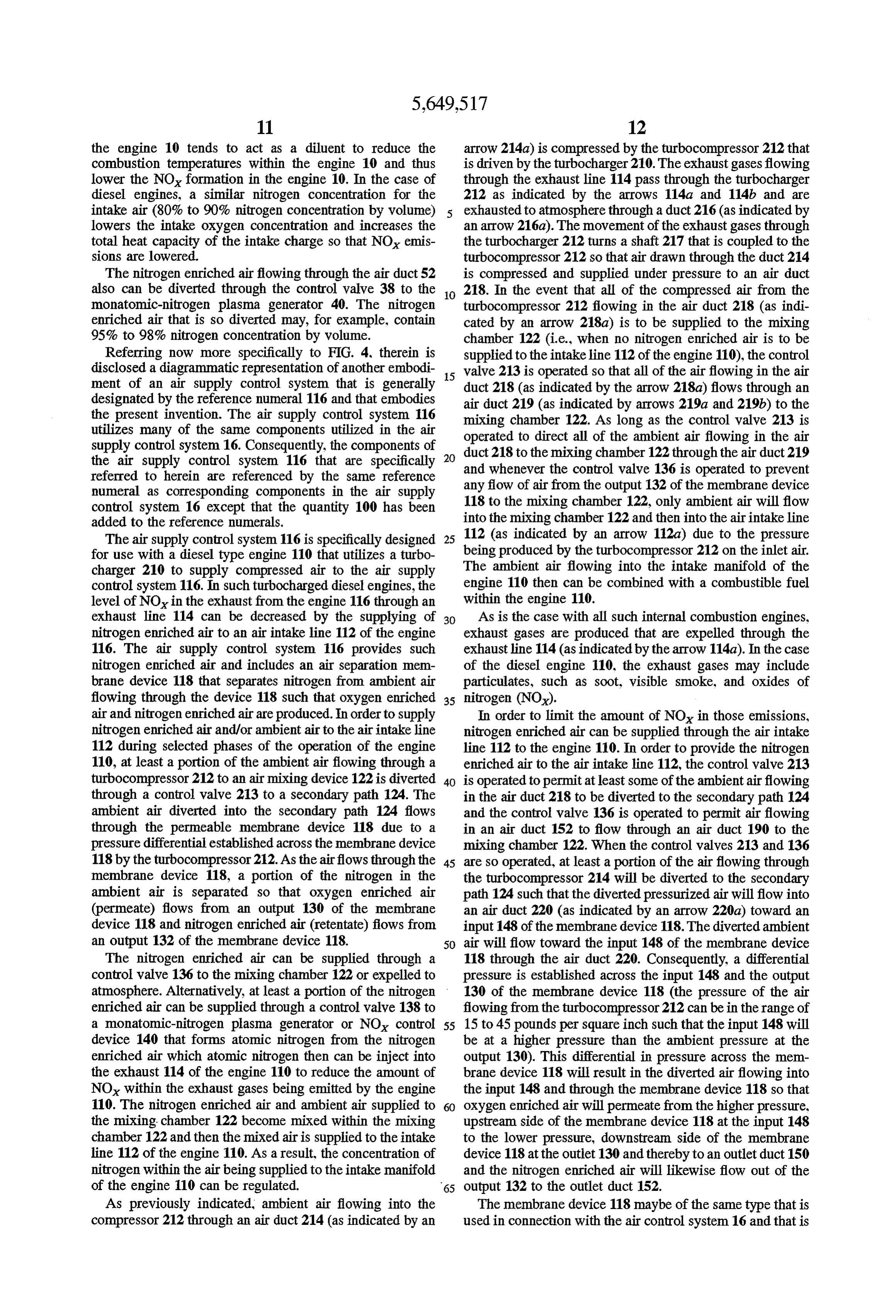
the engine 10 tends to act as a diluent to reduce the arrow 214a) is compressed by the turbocompressor 212 that combustion temperatures within the engine 10 and thus is driven by the turbocharger 210. The exhaust gases flowing lower the NO formation in the engine 10. In the case of through the exhaust line 114 pass through the turbocharger diesel engines, a similar nitrogen concentration for the 212 as indicated by the arrows 114a and 114b and are intake air (80% to 90% nitrogen concentration by volume) exhausted to atmosphere through a duct 216 (as indicated by lowers the intake oxygen concentration and increases the an arrow 216a). The movement of the exhaust gases through total heat capacity of the intake charge so that NO emis the turbocharger 212 turns a shaft 217 that is coupled to the sions are lowered. turbocompressor 212 so that air drawn through the duct 214 The nitrogen enriched airflowing through the air duct 52 is compressed and supplied under pressure to an air duct also can be diverted through the control valve 38 to the 10 218. In the event that all of the compressed air from the monatomic-nitrogen plasma generator 40. The nitrogen turbocompressor 212 flowing in the air duct 218 (as indi enriched air that is so diverted may, for example, contain cated by an arrow 218a) is to be supplied to the mixing 95% to 98% nitrogen concentration by volume. chamber 122 (i.e., when no nitrogen enriched air is to be Referring now more specifically to FIG. 4, therein is supplied to the intake line 112 of the engine 110), the control disclosed a diagrammatic representation of another embodi valve 213 is operated so that all of the airflowing in the air ment of an air supply control system that is generally 15 duct 218 (as indicated by the arrow 218a) flows through an designated by the reference numeral 116 and that embodies the present invention. The air supply control system 116 air duct 219 (as indicated by arrows 219a and 219b) to the utilizes many of the same components utilized in the air operatedchamber mixing to direct 122. As long as the control valve 213 is all of the ambient air flowing in the air supply control system 16. Consequently, the components of duct 218 to the mixing chamber 122 through the air duct 219 the air supply control system 116 that are specifically and whenever the control
valve 136 is operated to prevent referred to herein are referenced by the same reference any flow of air from the output 132 of the membrane device numeral as corresponding components in the air supply control system 16 except that the quantity 100 has been 118 to the mixing chamber 122, only ambient air will flow added to the reference numerals. into the mixing chamber 122 and then into the air intake line 112 (as indicated by an arrow 112a) due to the pressure
The air supply control system 116 is specifically designed 25 being for use with a diesel type engine 110 that utilizes a turbo produced by the turbocompressor 212 on the inlet air. charger 210 to supply compressed air to the air supply The ambient air flowing into the intake manifold of the control system 116. In such turbocharged diesel engines, the engine 110 then can be combined with a combustible fuel level of NO in the exhaust from the engine 116 through an within the engine 110.
exhaust line 114 can be decreased by the supplying of 30 As is the case with all such internal combustion engines, nitrogen enriched air to an air intake line 112 of the engine exhaust gases are produced that are expelled through the 116. The air supply control system 116 provides such exhaustline 114 (as indicated by the arrow 114a). In the case nitrogen enriched air and includes an air separation mem of the diesel engine 110, the exhaust gases may include brane device 118 that separates nitrogen from ambient air particulates, such as soot, visible smoke, and oxides of flowing through the device 118 such that oxygen enriched 35 nitrogen (NO).
air and nitrogen enriched air are produced. In order to supply In order to limit the amount of NO in those emissions, nitrogen enriched air and/or ambient air to the air intake line nitrogen enriched air can be supplied through the air intake 112 during selected phases of the operation of the engine line 112 to the engine 110. In order to provide the nitrogen 110, at least a portion of the ambient air flowing through a enriched air to the air intake line 112, the control valve 213 turbocompressor 212 to an air mixing device 122 is diverted 40 is operated to permitat least some of the ambient airflowing through a control valve 213 to a secondary path 124. The in the air duct 218 to be diverted to the secondary path 124 ambient air diverted into the secondary path 124 flows and the control valve 136 is operated to permit airflowing through the permeable membrane device 118 due to a in an air duct 152 to flow through an air duct 190 to the pressure differential established across the membrane device mixing chamber 122. When the control valves 213 and 136 118 by the turbocompressor 212. As the airflows through the 45 are so operated, at least a portion of the airflowing through membrane device 118, a portion of the nitrogen in the the turbocompressor 214 will be diverted to the secondary ambient air is separated so that oxygen enriched air path 124 such that the diverted pressurized air will flow into (permeate) flows from an output 130 of the membrane an air duct 220 (as indicated by an arrow 220a) toward an device 118 and nitrogen enriched air (retentate) flows from input 148 of the membrane device 118. The diverted ambient an output 132 of the membrane device 118. 50 air will flow toward the input 148 of the membrane device The nitrogen enriched air can be supplied through a 118 through the air duct 220. Consequently, a differential control valve 136 to the mixing chamber 122 or expelled to pressure is established across the input 148 and the output atmosphere. Alternatively, at least a portion of the nitrogen 130 of the membrane device 118 (the pressure of the air enriched air can be supplied through a control valve 138 to flowing from the turbocompressor 212 can be in the range of a monatomic-nitrogen plasma generator or NO control 55 15 to 45 pounds per square inch such that the input 148 will device 140 that forms atomic nitrogen from the nitrogen be at a higher pressure than the ambient pressure at the enriched air which atomic nitrogen then can be inject into output 130). This differential in pressure across the mem the exhaust 114 of the engine 110 to reduce the amount of brane device 118 will result in the diverted air flowing into NOx within the exhaust gases being emitted by the engine the input 148 and through the membrane device 118 so that 110. The nitrogen enriched air and ambient air supplied to 60 oxygen enriched air will permeate from the higher pressure, the mixing chamber 122 become mixed within the mixing upstream side of the membrane device 118 at the input 148 chamber 122 and then the mixed airis Supplied to the intake to the lower pressure, downstream side of the membrane line 112 of the engine 110. As a result, the concentration of device 118 at the outlet 130 and thereby to an outlet duct 150 nitrogen within the air being supplied to the intake manifold and the nitrogen enriched air will likewise flow out of the of the engine 110 can be regulated. 65 output 132 to the outlet duct 152. As previously indicated, ambient air flowing into the The membrane device 118 maybe of the same type that is compressor 212 through an air duct 214 (as indicated by an used in connection with the air control system 16 and that is
Page 11
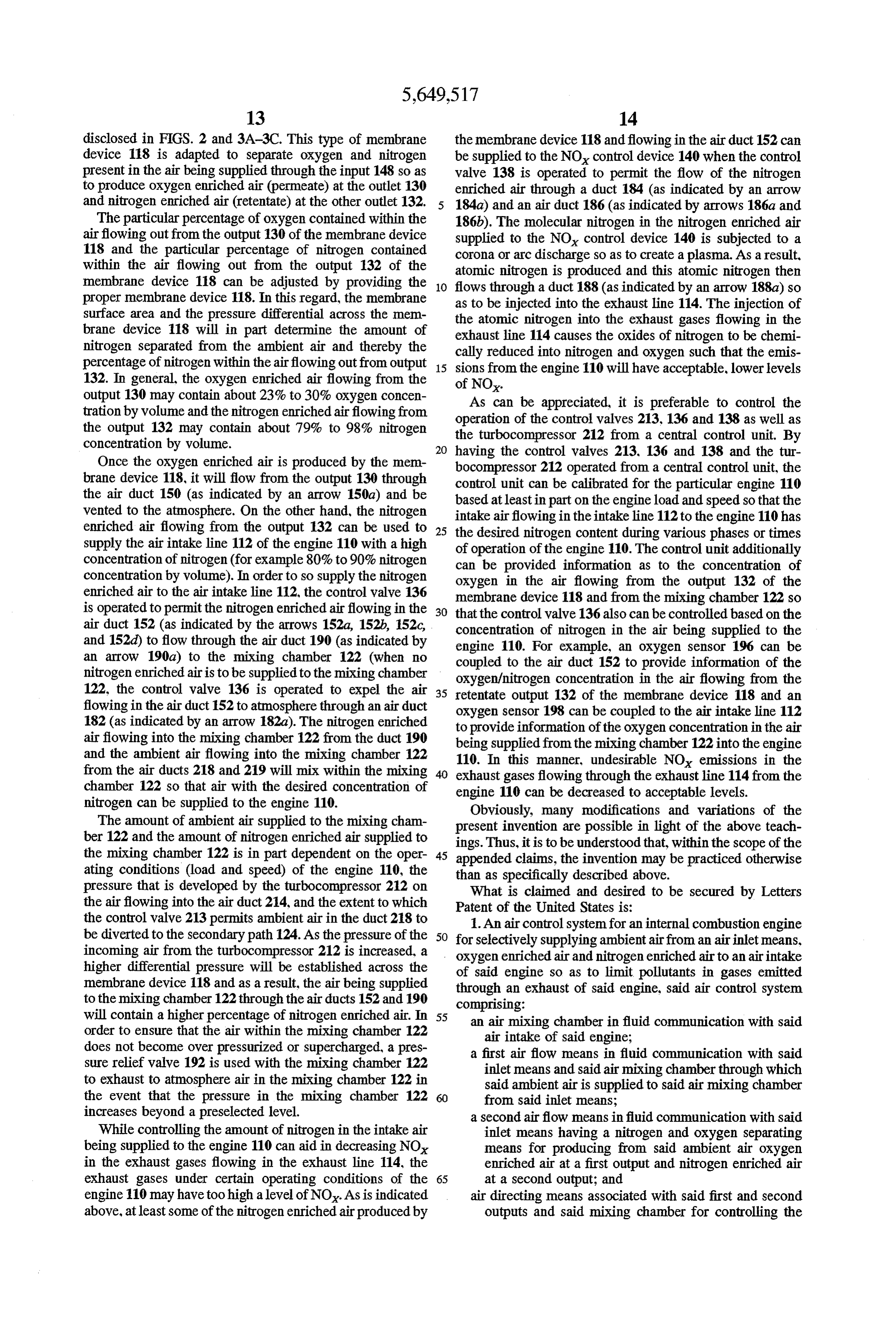
disclosed in FIGS. 2 and 3A-3C. This type of membrane the membrane device 118 and flowing in the air duct 152 can device 118 is adapted to separate oxygen and nitrogen be supplied to the NO control device 140 when the control present in the air being supplied through the input 148 so as valve 138 is operated to permit the flow of the nitrogen to produce oxygen enriched air (permeate) at the outlet 130 enriched air through a duct 184 (as indicated by an arrow and nitrogen enriched air (retentate) at the other outlet 132. 184a) and an air duct 186 (as indicated by arrows 186a and The particular percentage of oxygen contained within the 186b). The molecular nitrogen in the nitrogen enriched air airflowing out from the output 130 of the membrane device supplied to the NO control device 140 is subjected to a 118 and the particular percentage of nitrogen contained corona or arc discharge so as to create a plasma. As a result, within the air flowing out from the output 132 of the atomic nitrogen is produced and this atomic nitrogen then membrane device 118 can be adjusted by providing the 10 proper membrane device 118. In this regard, the membrane flows through a duct 188 (as indicated by an arrow 188a) so as to be injected into the exhaust line 114. The injection of
Surface area and the pressure differential across the mem the atomic nitrogen into the exhaust gases flowing in the brane device 118 will in part determine the amount of nitrogen separated from the ambient air and thereby the exhaust line 114 causes the oxides of nitrogen to be chemi percentage of nitrogen within the airflowing outfrom output 15 sions from theinto cally reduced nitrogen and oxygen such that the emis engine 110 will have acceptable, lower levels 132. In general, the oxygen enriched air flowing from the of NO.
output 130 may contain about 23% to 30% oxygen concen As can be appreciated, it is preferable to control the tration by volume and the nitrogen enriched airflowing from operation of the control valves 213, 136 and 138 as well as the output 132 may contain about 79% to 98% nitrogen the turbocompressor 212 from a central control unit. By concentration by volume.
Once the oxygen enriched air is produced by the mem having the control valves 213, 136 and 138 and the tur
bocompressor 212 operated from a central control unit, the brane device 118, it will flow from the output 130 through control unit can be calibrated for the particular engine 110 the air duct 150 (as indicated by an arrow 150a) and be based at leastin part on the engine load and speed so that the vented to the atmosphere. On the other hand, the nitrogen intake airflowing in the intake line 112 to the engine 110 has enriched air flowing from the output 132 can be used to 25 the desired nitrogen content during various phases or times supply the air intake line 112 of the engine 110 with a high of operation of the engine 110. The control unit additionally concentration of nitrogen (for example 80% to 90% nitrogen can be provided information as to the concentration of concentration by volume). In order to so supply the nitrogen oxygen in the air flowing from the output 132 of the enriched air to the air intake line 112, the control valve 136 membrane device 118 and from the mixing chamber 122 so is operated to permit the nitrogen enriched airflowing in the 30 that the control valve 136 also can be controlled based on the air duct 152 (as indicated by the arrows 152a, 152b, 152c, concentration of nitrogen in the air being supplied to the and 152d) to flow through the air duct 190 (as indicated by engine 110. For example, an oxygen sensor 196 can be an arrow 190a) to the mixing chamber 122 (when no coupled to the air duct 152 to provide information of the nitrogen enriched airis to be supplied to the mixing chamber oxygen/nitrogen concentration in the air flowing from the 122, the control valve 136 is operated to expel the air 35 retentate output 132 of the membrane device 118 and an flowing in the air duct152 to atmosphere through an air duct oxygen sensor 198 can be coupled to the air intake line 112 182 (as indicated by an arrow 182a). The nitrogen enriched to provide information of the oxygen concentration in the air airflowing into the mixing chamber 122 from the duct 190 being supplied from the mixing chamber 122 into the engine and the ambient air flowing into the mixing chamber 122 110. In this manner, undesirable NO emissions in the from the air ducts 218 and 219 will mix within the mixing exhaust gases flowing through the exhaust line 114 from the chamber 122 so that air with the desired concentration of engine 110 can be decreased to acceptable levels. nitrogen can be supplied to the engine 110. Obviously, many modifications and variations of the The amount of ambient air supplied to the mixing cham present invention are possible in light of the above teach ber 122 and the amount of nitrogen enriched air supplied to ings. Thus, it is to be understood that, within the scope of the the mixing chamber 122 is in part dependent on the oper 45 appended claims, the invention may be practiced otherwise ating conditions (load and speed) of the engine 110, the pressure that is developed by the turbocompressor 212 on thanWhat as specifically described above. the airflowing into the air duct 214, and the extent to which Patent ofistheclaimed and desired to be secured by Letters United States is:
the control valve 213 permits ambient air in the duct 218 to be diverted to the secondary path 124. As the pressure of the 50 for1.selectively
An air control system for an internal combustion engine supplying ambient airfrom an airinlet means.
incoming air from the turbocompressor 212 is increased, a oxygen enriched air and nitrogen enriched air to an air intake higher differential pressure will be established across the of said engine so as to limit pollutants in gases emitted membrane device 118 and as a result, the air being supplied through an exhaust of said engine, said air control system to the mixing chamber 122 through the air ducts 152 and 190 comprising:
will contain a higher percentage of nitrogen enriched air. In 55 an air mixing chamber in fluid communication with said order to ensure that the air within the mixing chamber 122 air intake of said engine; does not become over pressurized or supercharged, a pres a first air flow means in fluid communication with said sure relief valve 192 is used with the mixing chamber 122 inlet means and said air mixing chamber through which to exhaust to atmosphere air in the mixing chamber 122 in said ambient air is supplied to said air mixing chamber the event that the pressure in the mixing chamber 122 from said inlet means;
increases beyond a preselected level. a second airflow means in fluid communication with said While controlling the amount of nitrogen in the intake air inlet means having a nitrogen and oxygen separating being supplied to the engine 110 can aid in decreasingNO, means for producing from said ambient air oxygen in the exhaust gases flowing in the exhaust line 114, the enriched air at a first output and nitrogen enriched air exhaust gases under certain operating conditions of the 65 at a second output; and engine 110 may have too high a level of NO. As is indicated air directing means associated with said first and second above, at least some of the nitrogen enriched air produced by outputs and said mixing chamber for controlling the
Page 12
flow of said oxygen enriched air from said first output enriched air from said first output to said mixing to said mixing chamber and said nitrogen enriched air chamber; and from said second output to said mixing chamber such a nitrogen control valve between said second output and that said oxygen enriched air, said nitrogen enriched said mixing chamber for controlling the flow of said air, and said ambient air can be selectively provided nitrogen enriched air from said second output to said through said mixing chamber to said air intake of said mixing chamber such that said oxygen enriched air, engine.
2. An air control system as set forth in claim 1 wherein said nitrogen enriched air, and said ambient air can be said air directing means includes a first control valve for selectively provided through said mixing chamber to controlling the flow of oxygen enriched air from said first said air intake of said engine. output to said mixing chamber and a second control valve 10 air,13.nitrogen
A method of selectively supplying oxygen enriched enriched air and ambient air to a mixing controlling the flow of nitrogen enriched air from said chamber in fluid communication with an air intake of an second output to said mixing chamber.
3. An air control system as set forth in claim 1 wherein internal combustion engine so as to reduce the amount of said separating means includes a selectively permeable pollutants present in the gases being emitted from an exhaust membrane for separating nitrogen from ambient air so that 5 of said internal combustion engine, said method comprising: oxygen enriched air is produced at said first output and selectively diverting at least a portion of said ambient air nitrogen enriched air is produced at said second output. through a separating means so that oxygen enriched air 4. An air control system as set forth in claim 3 wherein is produced at a first output of said separating means said selectively permeable membrane includes hollow poly and nitrogen enriched air is produced at a second output mer fibers that separate nitrogen and oxygen from ambient 20 of said separating means; and
selectively controlling the flow of said oxygen enriched 5. An air control system as set forth in claim 4 wherein air from said first output to said mixing chamber and said hollow polymer fibers are in fiber bundles disposed in selectively controlling the flow of said nitrogen cartridges within an outer housing. enriched air from said second output to said mixing 6. An air control system as set forth in claim 5 wherein chamber whereby the air being supplied from said said hollow polymer fibers are formed of perfluorodioxole 25 mixing chamber to said air intake of said engine membrane material. contains a desired concentration of oxygen and nitro 7. An air control system as set forth in claim 1 wherein gen.
said separating means produces oxygen enriched air con 14. A method as set forth in claim 13 wherein said taining about 23%-30% oxygen concentration by volume at separating means includes selectively permeable membrane said first output. 30 CalS.
8. An air control system as set forth in claim 1 wherein 15. A method as set forth in claim 13 wherein said oxygen said separating means produces nitrogen enriched air con enriched air contains 23%-30% oxygen concentration by taining about 79%-98% nitrogen concentration by volume Volume.
at said second output. 16. A method as set forth in claim 13 wherein said 9. An air control system as set forth in claim 1 including 35 nitrogen enriched air contains 79%–98% nitrogen concen a pressure differential means associated with said separating tration by volume.
means to establish a differential pressure across said sepa 17. An air control system for an internal combustion rating means so that at least a portion of said ambient air engine, said engine having a pressure means for providing flows through said separating means. pressurized ambient air, for selectively supplying ambient 10. An air control system as set forth in claim 1 including 40 air and nitrogen enriched air to an air intake of said engine a nitrogen control valve means associated with said sepa so as to limit pollutants in gases emitted through an exhaust rating means to control the flow of nitrogen enriched air of said engine, said air control system comprising: from said second output to a nitrogen oxide control means, an air mixing chamber in fluid communication with said said nitrogen oxide control means producing monatomic air intake of said engine; nitrogen to be injected into said exhaust of said engine to 45 a first air flow means in fluid communication with said reduce oxides of nitrogen in said exhaust. pressure means and said air mixing chamber through 11. An air control system as set forth in claim 1 including which said ambient air is supplied to said air mixing oxygen sensing means associated with said first output, said chamber from said pressure means; second output and said air intake. a second airflow means in fluid communication with said 12. An air control system for an internal combustion pressure means having a nitrogen and oxygen separat engine for selectively supplying ambient air from an airinlet 50 ing means for producing from said ambient air oxygen means, oxygen enriched air and nitrogen enriched air to an enriched air at a first output and nitrogen enriched air air intake of said engine so as to limit pollutants in gases at a second output, said ambient air flowing through emitted through an exhaust of said engine, said air control said separating means due to the differential pressure system comprising: produced across said separating means by said pressure
an air mixing chamber in fluid communication with said means; and air intake of said engine; air directing means associated with said second output a first air flow means in fluid communication with said and said mixing chamber for controlling the flow of inlet means and said air mixing chamber through which said nitrogen enriched air from said second output to said ambient air is supplied to said air mixing chamber 60 said mixing chamber such that said nitrogen enriched from said inlet means; air and said ambient air can be selectively provided a second airflow means in fluid communication with said through said mixing chamber to said air intake of said inlet means having a nitrogen and oxygen separating engine.
means for producing from said ambient air oxygen 18. An air control system as set forth in claim 17 wherein enriched air at a first output and nitrogen enriched air said pressure means is a turbocompressor operated by a at a second output; 65 turbocharger associated with said exhaust of said engine. an oxygen control valve between said first output and said mixing chamber for controlling the flow of said oxygen
Provenance
- Collection
- Cited prior art
- Original PDF
- patentimages.storage.googleapis.com →
- Filed
- 1996-09-18
- Pages
- 12
- Method
- pdftotext (the PDF's own text layer) + pdftoppm 300dpi page scans
- Source
- Google Patents bibliographic record
- Granted
- 1997-07-22
- Inventors
- Ramesh B. Poola; Ramanujam R. Sekar; Roger L. Cole; University of Chicago
- Transcribed from
- patentimages.storage.googleapis.com →