patent · US3217791
Means for maintaining perma-frost foundations
16 November 1965
Page 1
Drawing sheet — no readable text.
Page 2
Drawing sheet — no readable text.
Page 3
Drawing sheet — no readable text.
Page 4
Drawing sheet — no readable text.
Page 5
United States Patent Office Patented Nov. 6, 1965
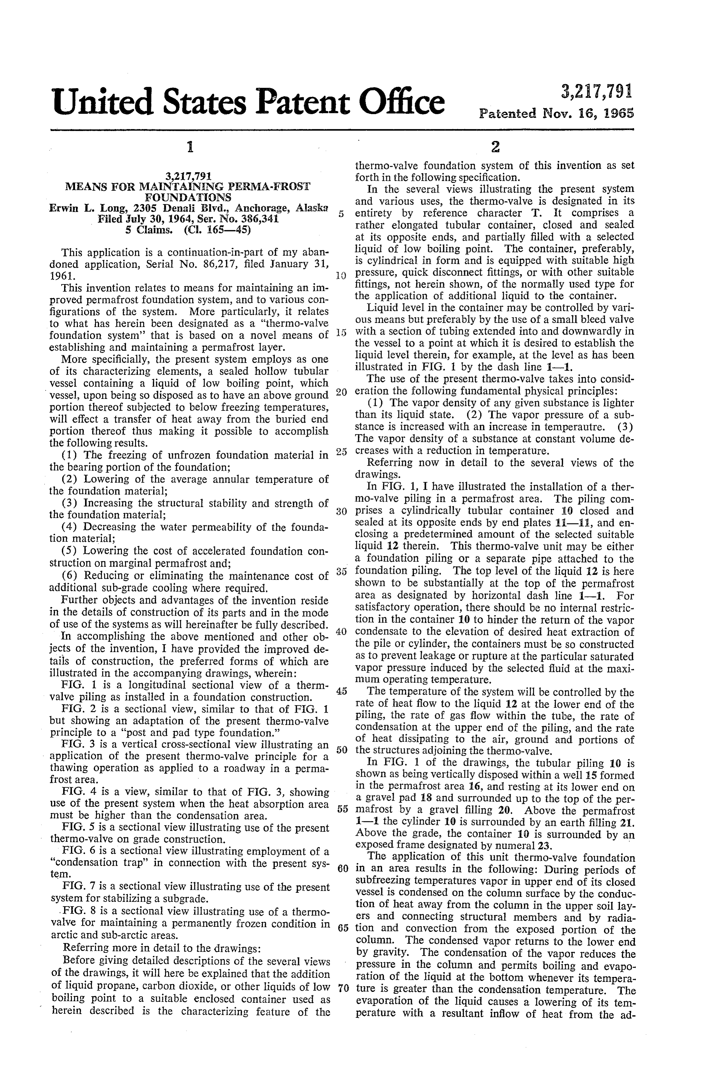
thermo-valve foundation system of this invention as set 3,217,791 forth in the following specification.
MEANS FOR MANTANNG PERMAFROST In the several views illustrating the present system
FOUNDATATIONS
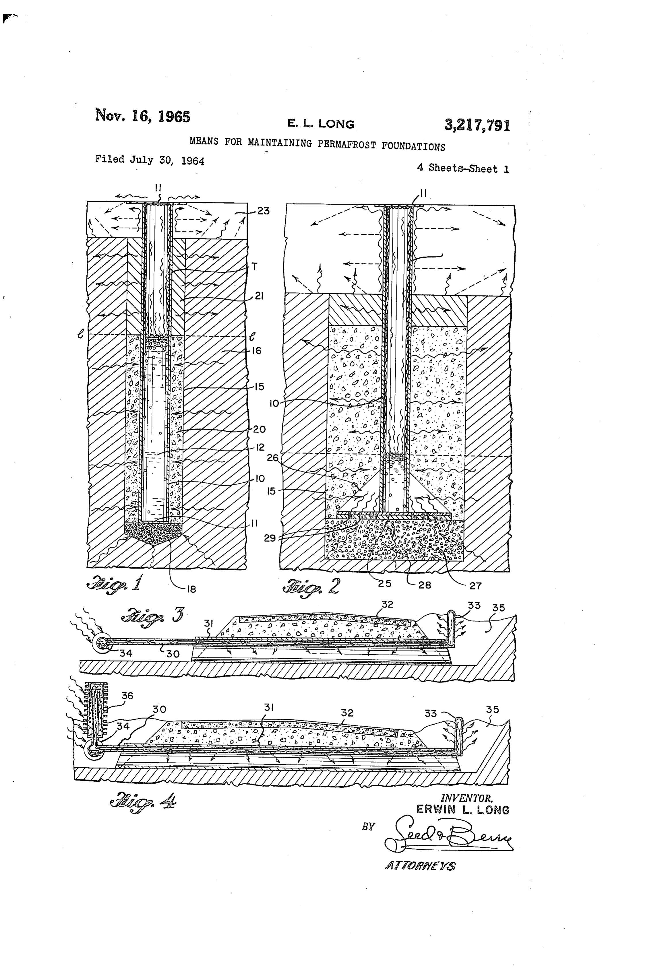
Erwin L. Long, 2305 Denai Blvd., Anchorage, Alaska 5 and various uses, the thermo-valve is designated in its entirety by reference character T. It comprises a
Filed July 30, 1964, Ser. No. 386,341 rather elongated tubular container, closed and sealed 5 Claims. (C. 165-45) at its opposite ends, and partially filled with a selected This application is a continuation-in-part of my aban liquid of low boiling point. The container, preferably, doned application, Serial No. 86,217, filed January 31, is cylindrical in form and is equipped with suitable high 1961. O pressure, quick disconnect fittings, or with other Suitable This invention relates to means for maintaining an im fittings, not herein shown, of the normally used type for proved permafrost foundation System, and to various con the application of additional liquid to the container. figurations of the system. More particularly, it relates Liquid level in the container may be controlled by vari to what has herein been designated as a "thermo-valve ous means but preferably by the use of a small bleed valve foundation system that is based on a novel means of With a section of tubing extended into and downwardly in establishing and maintaining a permafrost layer. the vessel to a point at which it is desired to establish the More specificially, the present system employs as one liquid level therein, for example, at the level as has been of its characterizing elements, a sealed hollow tubular illustrated in FIG. 1 by the dash line 1-1. vessel containing a liquid of low boiling point, which The use of the present thermo-valve takes into consid vessel, upon being so disposed as to have an above ground 20 eration the following fundamental physical principles: (1) The vapor density of any given substance is lighter portion thereof subjected to below freezing temperatures, will effect a transfer of heat away from the buried end than its liquid state. (2) The vapor pressure of a sub portion thereof thus making it possible to accomplish stance is increased with an increase in temperautre. (3) the following results. The vapor density of a substance at constant volume de (1) The freezing of unfrozen foundation material in creases with a reduction in temperature. the bearing portion of the foundation; Referring now in detail to the several views of the (2) Lowering of the average annular temperature of drawings.
the foundation material; In FIG. 1, I have illustrated the installation of a ther (3) Increasing the structural stability and strength of 30 mo-Valve piling in a permafrost area. The piling com prises a cylindrically tubular container 10 closed and the foundation material; sealed at its opposite ends by end plates 11-55, and en (4) Decreasing the water permeability of the founda closing a predetermined amount of the selected suitable tion material;
(5) Lowering the cost of accelerated foundation con liquid 2 therein. This thermo-valve unit may be either Struction on marginal permafrost and; a foundation piling or a separate pipe attached to the (6) Reducing or eliminating the maintenance cost of foundation piling. The top level of the liquid 2 is here additional sub-grade cooling where required. shown to be substantially at the top of the permafrost Further objects and advantages of the invention reside area as designated by horizontal dash line 1-1. For in the details of construction of its parts and in the mode Satisfactory operation, there should be no internal restric tion in the container 10 to hinder the return of the vapor of use of the systems as will hereinafter be fully described. 40 Condensate
In accomplishing the above mentioned and other ob to the elevation of desired heat extraction of jects of the invention, I have provided the improved de the pile or cylinder, the containers must be so constructed tails of construction, the preferred forms of which are as to prevent leakage or rupture at the particular saturated illustrated in the accompanying drawings, wherein: Vapor pressure induced by the selected fluid at the maxi FIG. 1 is a longitudinal sectional view of a therm 45 nunn operating temperature.
The temperature of the system will be controlled by the valve piling as installed in a foundation construction. rate of heat flow to the liquid 12 at the lower end of the FIG. 2 is a sectional view, similar to that of FIG. 1 piling, the rate of gas flow within the tube, the rate of but showing an adaptation of the present thermo-valve Condensation at the upper end of the piling, and the rate principle to a "post and pad type foundation.”
FIG. 3 is a vertical cross-sectional view illustrating an 50 the heat of dissipating to the air, ground and portions of structures adjoining the thermo-valve.
application of the present thermo-valve principle for a In FIG. 1 of the drawings, the tubular piling 10 is thawing operation as applied to a roadway in a perma shown as being vertically disposed within a well 15 formed frost area.
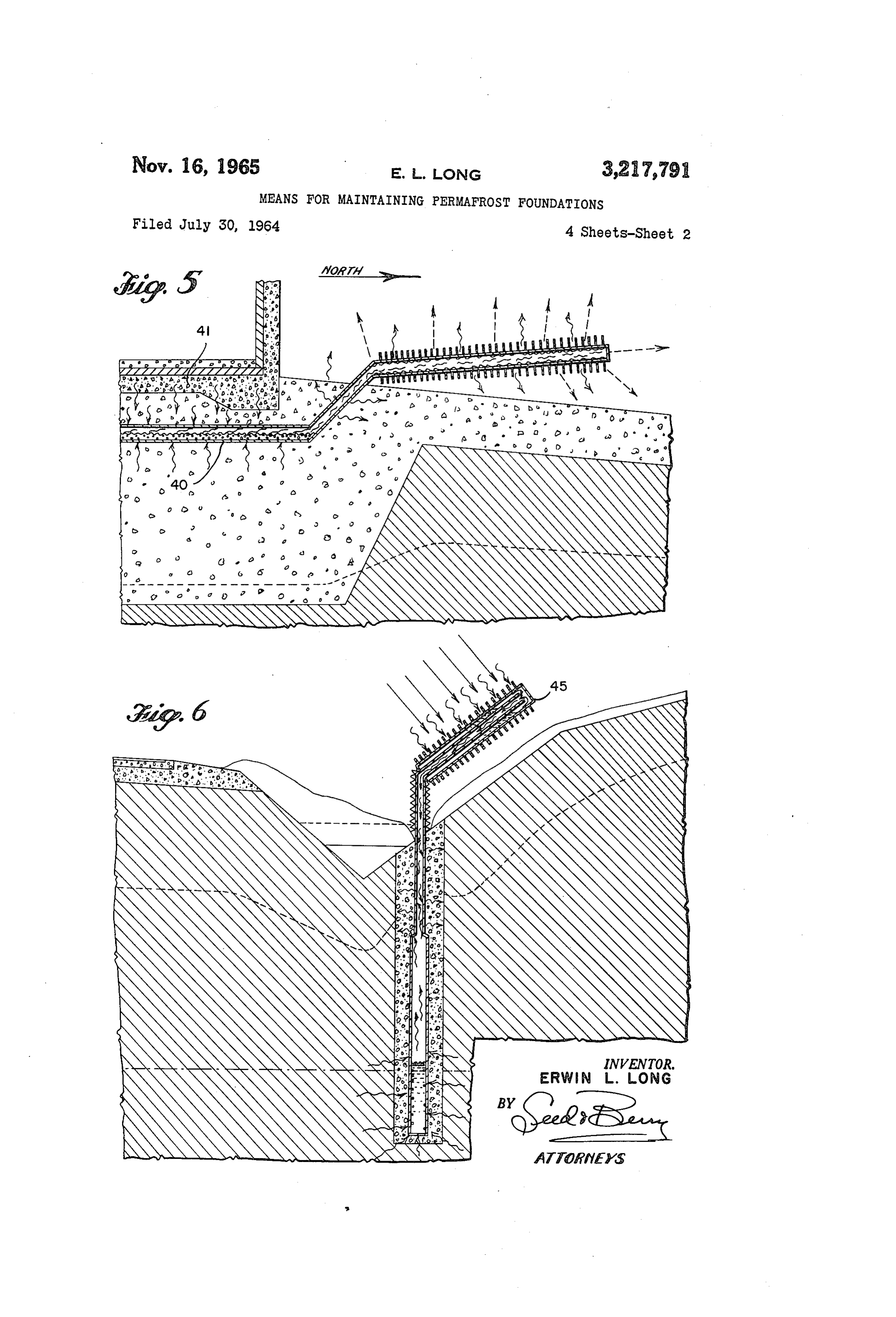
FIG. 4 is a view, similar to that of FIG. 3, showing in the permafrost area 16, and resting at its lower end on a gravel pad 18 and Surrounded up to the top of the per use of the present system when the heat absorption area 55 mafrost must be higher than the condensation area. by a gravel filling 20. Above the permafrost FIG. 5 is a sectional view illustrating use of the present 1-1 the cylinder 10 is surrounded by an earth filling 21. thermo-valve on grade construction. Above the grade, the container 10 is surrounded by an FIG. 6 is a sectional view illustrating employment of a exposed frame designated by numeral 23. "condensation trap' in connection with the present sys 60 in The application of this unit thermo-valve foundation an area results in the following: During periods of tem.
Subfreezing temperatures vapor in upper end of its closed
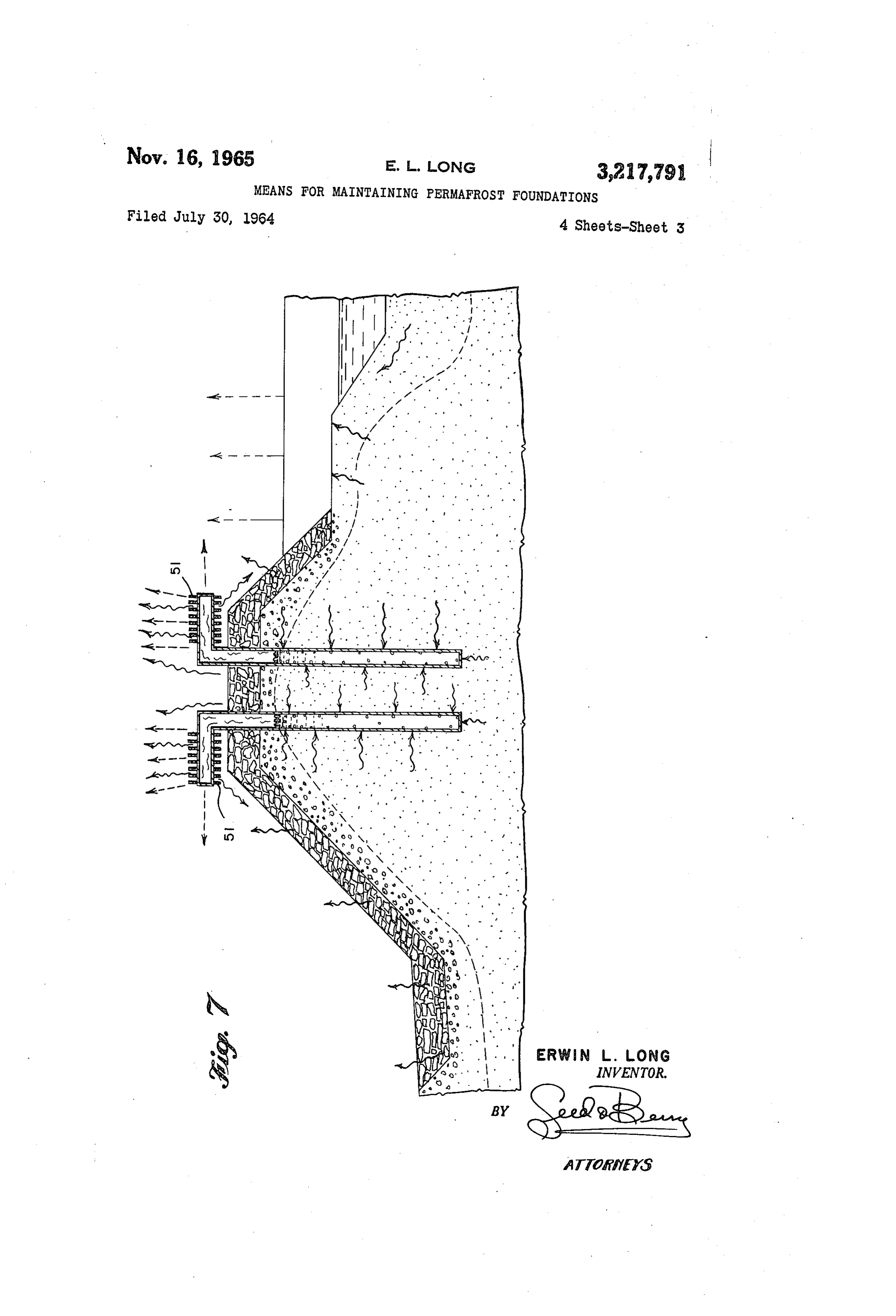
FIG. 7 is a sectional view illustrating use of the present Vessel
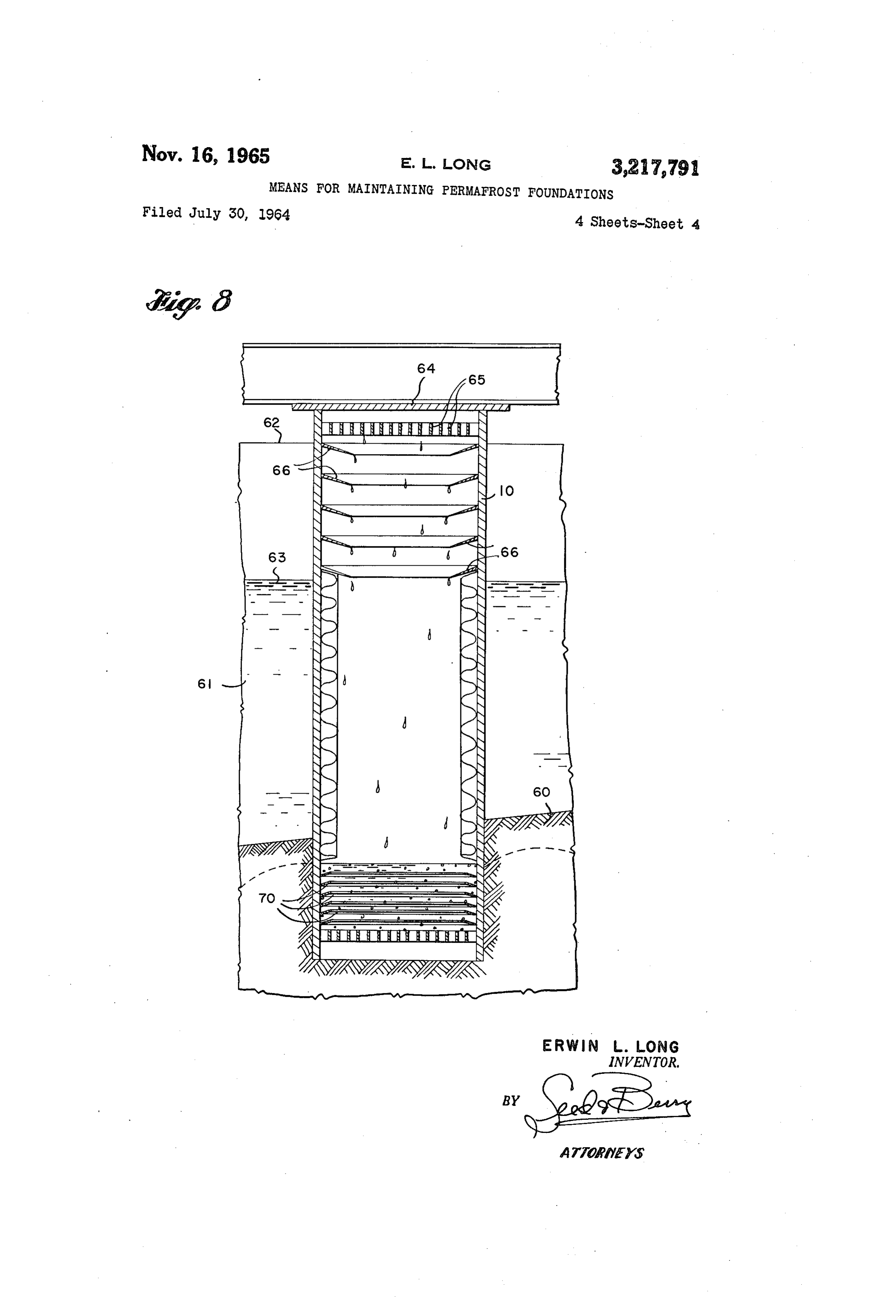
System for stabilizing a subgrade. is condensed on the column surface by the conduc FIG. 8 is a sectional view illustrating use of a thermo tion of heat away from the column in the upper soil lay valve for maintaining a permanently frozen condition in 65 tion and Connecting ers and structural members and by radia convection from the exposed portion of the arctic and Sub-arctic areas.
Referring more in detail to the drawings: column. The condensed vapor returns to the lower end Before giving detailed descriptions of the several views by gravity. The condensation of the vapor reduces the of the drawings, it will here be explained that the addition pressure in the column and permits boiling and evapo ration of the liquid at the bottom whenever its tempera of liquid propane, carbon dioxide, or other liquids of low 70 ture is greater than the condensation temperature. The boiling point to a suitable enclosed container used as evaporation of the liquid causes a lowering of its tem herein described is the characterizing feature of the perature with a resultant inflow of heat from the ad
Page 6
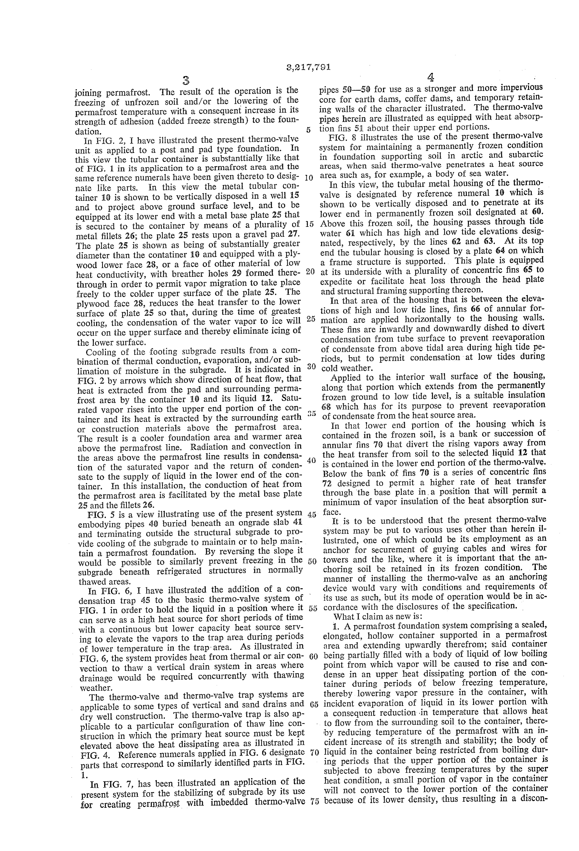
joining permafrost. The result of the operation is the pipes 50-50 for use as a stronger and more impervious freezing of unfrozen soil and/or the lowering of the core for earth dams, coffer dams, and temporary retain permafrost temperature with a consequent increase in its ing walls of the character illustrated. The thermo-valve strength of adhesion (added freeze strength) to the foun pipes herein are illustrated as equipped with heat absorp dation. tion fins 51 about their upper end portions. In F.G. 2, I have illustrated the present thermo-valve FIG. 8 illustrates the use of the present thermo-valve unit as applied to a post and pad type foundation. In system for maintaining a permanently frozen condition this view the tubular container is substantitially like that in foundation supporting soil in arctic and Subarctic of FIG. 1 in its application to a permafrost area and the areas, when said thermo-valve penetrates a heat source Same reference numerals have been given thereto to desig O area such as, for example, a body of Sea water. nate like parts. in this view the metal tubular con In this view, the tubular metal housing of the thermo tainer () is shown to be vertically disposed in a well 5 valve is designated by reference numeral 10 which is and to project above ground surface level, and to be shown to be vertically disposed and to penetrate at its equipped at its lower end with a metal base plate 25 that lower end in permanently frozen soil designated at 60. is Secured to the container by means of a plurality of 5 Above this frozen soil, the housing passes through tide metal fillets 26; the plate 25 rests upon a gravel pad 27. water 6, which has high and low tide elevations desig The plate 25 is shown as being of substantially greater nated, respectively, by the lines 62 and 63. At its top diameter than the contatiner 10 and equipped with a ply end the tubular housing is closed by a plate 64 on which wood lower face 28, or a face of other material of low a frame structure is supported. This plate is equipped at its underside with a plurality of concentric fins 65 to heat conductivity, with breather holes 29 formed there 20 expedite through in order to permit vapor migration to take place or facilitate heat loss through the head plate freely to the colder upper surface of the plate 25. The and structural framing supporting thereon. plywood face 28, reduces the heat transfer to the lower In that area of the housing that is between the eleva surface of plate 25 so that, during the time of greatest 25 tions of high and low tide lines, fins 66 of annular for mation are applied horizontally to the housing walls.
cooling, the condensation of the water vapor to ice will These fins are inwardly and downwardly dished to divert occur on the upper Surface and thereby eliminate icing of the lower surface. condensation from tube surface to prevent reevaporation Cooling of the footing subgrade results from a com of condensate from above tidal area during high tide pe bination of thermal conduction, evaporation, and/or sub 30 riods, cold but to permit condensation at low tides during weather.
limation of moisture in the subgrade. It is indicated in Applied to the interior wall surface of the housing, FIG. 2 by arrows which show direction of heat flow, that along that portion which extends from the permanently heat is extracted from the pad and surrounding perma frost area by the container 0 and its liquid 42. Satu frozen ground to low tide level, is a suitable insulation rated vapor rises into the upper end portion of the con 5 68 which has for its purpose to prevent reevaporation of condensate from the heat source area.
tainer and its heat is extracted by the surrounding earth In that lower end portion of the housing which is or construction materials above the permafrost area.
The result is a cooler foundation area and warmer area contained in the frozen soil, is a bank or succession of above the permafrost line. Radiation and convection in annular fins 70 that divert the rising vapors away from the areas above the permafrost line results in condensa 40 the heat transfer from soil to the selected liquid 12 that tion of the saturated vapor and the return of conden is contained in the lower end portion of the thermo-valve. sate to the supply of liquid in the lower end of the con Below the bank of fins 70 is a series of concentric fins tainer. In this installation, the conduction of heat from 72 designed to permit a higher rate of heat transfer the permafrost area is facilitated by the metal base plate through the base plate in a position that will permit a 25 and the fillets 26. minimum of vapor insulation of the heat absorption sur FIG. 5 is a view illustrating use of the present system 45 face.
embodying pipes 40 buried beneath an ongrade slab 4. It is to be understood that the present thermo-valve and terminating outside the structural subgrade to pro system may be put to various uses other than herein il vide cooling of the subgrade to maintain or to help main lustrated, one of which could be its employment as an tain a permafrost foundation. By reversing the slope it anchor for securement of guying cables and wires for would be possible to similarly prevent freezing in the towers and the like, where it is important that the an subgrade beneath refrigerated structures in normally choring soil be retained in its frozen condition. The thawed areas. manner of installing the thermo-valve as an anchoring In FIG. 6, I have illustrated the addition of a con device would vary with conditions and requirements of densation trap 45 to the basic thermo-valve system of its use as such, but its mode of operation would be in ac FIG. 1 in order to hold the liquid in a position where it cordance with the disclosures of the specification. can serve as a high heat source for short periods of time What I claim as new is:
with a continuous but lower capacity heat source Serv elongated, 1. A permafrost foundation system comprising a sealed, ing to elevate the vapors to the trap area during periods hollow container supported in a permafrost of lower temperature in the trap area. As illustrated in area and extending upwardly therefrom; said container being partially filled with a body of liquid of low boiling
FIG. 6, the system provides heat from thermal or air con 60 point from which vapor will be caused to rise and con vection to thaw a vertical drain system in areas where drainage would be required concurrently with thawing dense tainer in an upper heat dissipating portion of the con during periods of below freezing temperature, weather.
The thermo-valve and thermo-valve trap Systems are thereby lowering vapor pressure in the container, with applicable to some types of vertical and sand drains and 65 incident
evaporation of liquid in its lower portion with consequent reduction in temperature that allows heat dry well construction. The thermo-valve trap is also ap to flow from the surrounding soil to the container, there plicable to a particular configuration of thaw line con by reducing temperature of the permafrost with an in struction in which the primary heat source must be kept cident elevated above the heat dissipating area as illustrated in liquid inincrease of its strength and stability; the body of the container being restricted from boiling dur
FIG. 4. Reference numerals applied in FIG. 6 designate ing periods parts that correspond to similarly identified parts in FIG. subjected to that above the upper portion of the container is freezing temperatures by the super
In FIG. 7, has been illustrated an application of the heat condition, a small portion of vapor in the container present system for the stabilizing of subgrade by its use will not convect to the lower portion of the container for creating permafrost with imbedded thermo-valve 75 because of its lower density, thus resulting in a discon
Page 7
tinuance of thermal activity during periods of above positioned in a tidal water area and said container is freezing temperatures; said container being composed of provided on the inside by concentric rings whereby liquid metal and being closed at its lower end by a metal disc condensate is diverted away from its walls to prevent its of substantially greater diameter than the diameter of reevaporation within the tidal height when in contact the container; a disc of low conductivity applied to the 5 with the tidal waters but yet to permit condensation lower surface of the metal disc; both of said discs having between these rings to effect the refreezing of the un a plurality of aligned holes formed therein at greater derwater foundation during low tidal levels when the radii from the axial center of the container than the tidal water is not in contact with that portion of the tubular container, to permit water vapor to pass up container.
wardly through said holes to the upper colder surface of O 4. A permafrost foundation system including a device the disc and thereby eliminate detrimental icing of the for maintaining a permafrost layer of earth properly lower Surface of the disc, frozen wherein the permafrost layer includes a surface 2. A permafrost foundation System comprising a sealed, layer having an upper surface exposed to the atmosphere, elongated, tubular container supported in a permafrost Said device comprising an elongated, generally vertically area and extending upwardly therefrom, said container extending body, said body including a sealed chamber being partially filled with a body of liquid of low boiling extending from a lower end portion to an upper end point from which a vapor will be caused to rise and portion thereof and said upper portion extending into condense in an upper heat dissipating portion of the the atmosphere above said upper surface, a central por container during periods of below freezing temperatures, tion extending through said surface layer and a lower thereby lowering vapor pressure in the container with 20 portion extending into said permafrost area below said incident evaporation of liquid in its lower portion with Surface layer, the lower portion of said chamber being a consequent reduction in temperature that allows heat filled with a liquid whose vapors will condense below to flow from the surrounding soil to the container, there the thawing temperature of said permafrost layer, the by reducing temperature of the permafrost with an in remainder of said chamber being filled with the vapors cident increase of its strength and stability, the body of said liquid, heat dissipating means on said upper of liquid of the container being restricted from boiling portion capable of dissipating heat from said vapors to during periods that the upper portion of the container atmosphere when the temperature of the atmosphere is is subjected to above freezing temperatures by the super below the thawing temperature of Said permafrost layer heat condition, a small portion of vapor in the container whereby said vapors will condense and flow into said will not convect to the lower portion of the container 30 lower portion and again absorb heat from said perma because of its lower density thus resulting in a discon frost layer and cause said liquid to vaporize and a layer tinuance of thermal activity during periods of above of gravel completely surrounding said lower portion and freezing temperatures; said container being composed of spacing said lower portion from said permafrost layer. metal and being closed at its lower end by a metal disc 5. A permafrost foundation system as defined in claim of substantially greater diameter than the diameter of 35 4 wherein said liquid is selected from the group con the container, a disc of lower conductivity applied to sisting of carbon dioxide and propane. a lower face of the metal disk, both discs having a plurality of aligned holes formed therein at greater radii References (Cited by the Examiner from the center than the tubular container, to permit water vapor to pass upwardly through said holes to the 40 FOREIGN PATENTS upper, colder surface of the disc and thereby eliminate 475,226 4/1915 France. detrimental icing of the lower surface of the disc.
3. The system of claim 2 wherein said container is CHARLES SUKALO, Primary Examiner.
Provenance
- Collection
- Cited prior art
- Original PDF
- patentimages.storage.googleapis.com →
- Filed
- 1964-07-30
- Pages
- 7
- Method
- pdftotext (the PDF's own text layer) + pdftoppm 300dpi page scans
- Source
- Google Patents bibliographic record
- Granted
- 1965-11-16
- Inventors
- Erwin L Long
- Transcribed from
- patentimages.storage.googleapis.com →