patent · US3681002
Self-igniting burners
1 August 1972
Page 1 — bibliographic record
United States Patent (15) 3,681,002 Weller et al. (45) Aug. 1, 1972 (54) SELF-IGNITING BURNERS 3,191,659 6/1965 Weiss............................431/328
(72) Inventors; Ave., her Downers
Grove, Ill. 60515; Siggs; 33. GM. 431/4
William R. Staats, 300 Wabash 3,518,036 6/1970 Statts et al....................431/268 Ave., Chicago, Ill. 60616; Robert B. 1,225,381 5/1917 Wedge.......................... 431/328 Rosenberg,9138 Mozart, Evergreen Primary Examiner-Frederick L. Matteson
Park, Ill. 62203 Assistant Examiner-Harry B. Ramey 22 Filed: Oct. 20, 1969 Attorney-Dominik, Knechtel & Godula 21 Appl. No.: 867,480 57 ABSTRACT (52) U.S.C....................................431/268,431/328 A self-igniting gas burner which includes, generally, an 51) Int. Cl...............................................F23d 13/16 oxidation catalyst which is supported by means of a
gas-permeable catalyst support plate. A mixture of 431/328,329 gaseous fuel is supplied to and permeates through the catalyst support plate. In doing so, the gaseous fuel is oxidized to cause combustion. The combustion of the 56) References Cited gaseous fuel heats the catalyst support plate which UNITED STATES PATENTS then radiates heat to a load. The hot products of reac tion also pass through the catalyst support plate, to 64,188 4/1867 Barbarin.......................431/268 heat the load.
2,745,042 5/1956 Hoff..........................431/256 X 2 Claims, 7 Drawing Figures
Page 2
Drawing sheet — no readable text.
Page 3
SELF-IGNITING BURNERS Still another object is to provide improved self-ignit This invention relates to improved self-igniting gas ing flameless gas burners of the above-described type burners and, more particularly, it relates to improved wherein ignition is provided by catalysis of an initially self-igniting gas burners which operate on natural gas cool surface.
rather than manufactured gas and which are flameless. Other objects of the invention will in part be obvious Presently, most, if not all gas applicances operate on and will in part appear hereinafter.
natural gas rather than manufactured gas, and natural The above objectives are accomplished by means of gas contains mostly methane. Numerous attempts have a self-igniting gas burner which includes, generally, an been made by those skilled in the art to construct a true oxidation catalyst which is supported by means of a catalytic igniter for natural gas, however, none of these 10 gas-permeable catalyst support plate. A mixture of attempts have been successful. In fact, the reports gaseous fuel is supplied to and permeates through the given on these prior attempts generally conclude that catalyst support plate. In doing so, the gaseous fuel is methane cannot be catalytically ignited by a solid oxidized to cause combustion. The combustion of the catalyst below approximately 200°F. gaseous fuel heats the catalyst support plate which then In a copending application, there is disclosed an im 15 radiates heat to the load. The hot products of reaction proved apparatus and true catalytic ignition process for also pass through the catalyst support plate, to heat the igniting natural gas, using a cold catalyst. This process load.
includes, generally, the steps o3 mixing a small amount The invention accordingly comprises the several of hydrogen with natural gas, impinging this mixture of steps and the relation of one or more of such steps with hydrogen and natural gas onto a cold solid catalyst, that 20 respect to each of the others and the apparatus em is, one at ambient temperatures, to cause the latter to heat up to a high enough temperature to ignite the mix bodying features of construction, combination of ele ments and arrangement of parts which are adapted to ture, and stopping the flow of hydrogen which is mixed effect such steps, all as exmplified in the following with the natural gas after ignition has occurred. detailed disclosure, and the scope of the invention will It has been found that the same general principle can 25 be indicated in the claims.
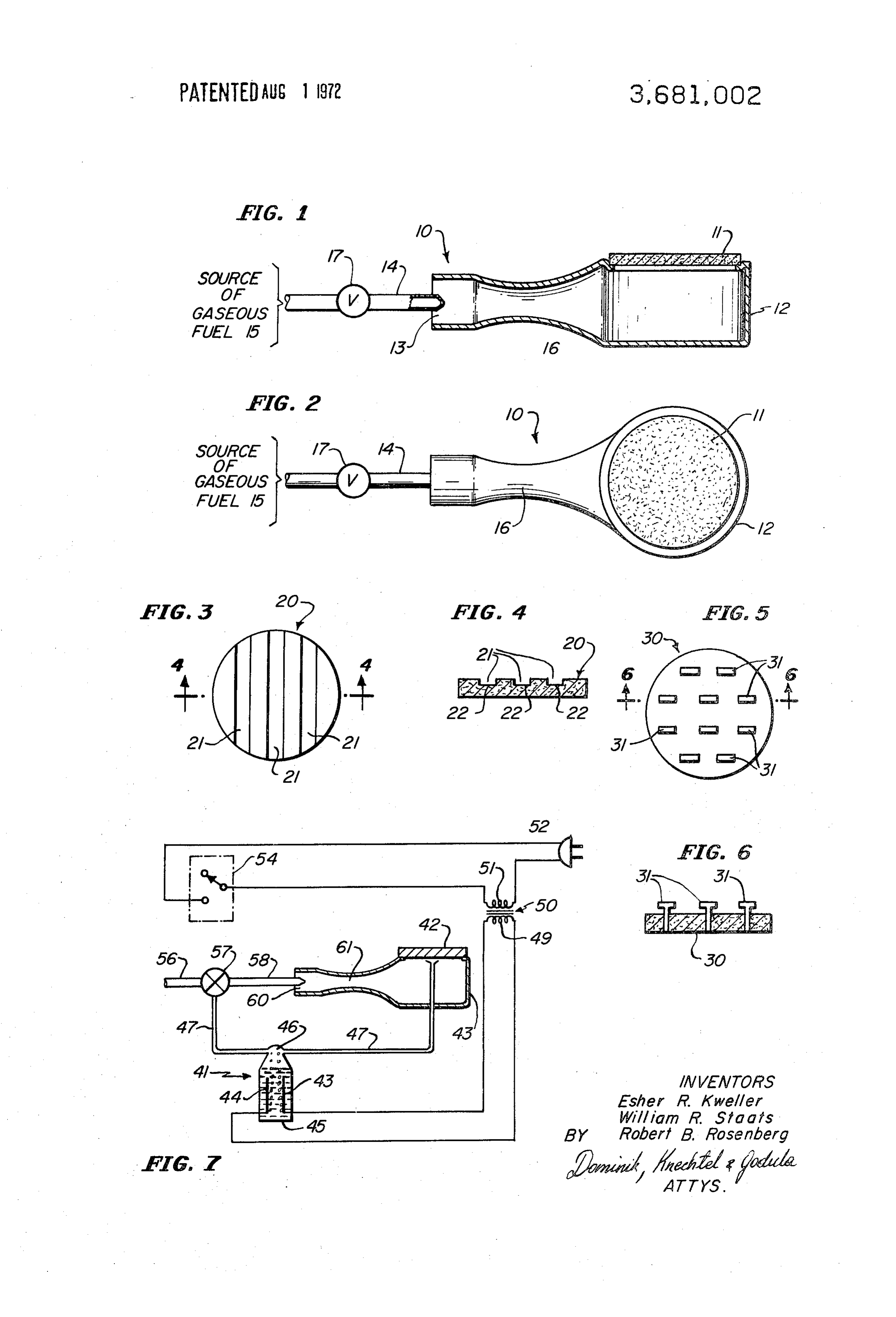
be used to provide a self-igniting flameless gas burner. For a fuller understanding of the nature and objects Presently, there are available various different types of of the invention, reference should be had to the follow gas burners which are generally referred to as "flame ing detailed description taken in connection with the less.' However, it is only after the stream of gaseous accompanying drawings in which:
fuel supplied thereto is ignited by means of some exter 30 FIG. 1 is a side plan view, partly sectionalized, of a nal ignition source and this flame heats the "burner self-igniting flameless gas burner exemplary of the in plate' to a sufficiently high temperature to support vention;
combustion on its surface that the gas burner is "flame less." That is, when the surface of the "burner plate" is 35 FIG, FIGS.
2 is a top plan view of the burner of FIG. 1;
3 and 4 are a top plan view and a sectional sufficiently hot to support combustion, the flame is view, respectively, of a catalyst support plate; drawn onto the surface of the "burner plate' and com bustion continues in a flameless fashion. The self-ignit view, respectively, ofaanother
FIGS. 5 and 6 are top plan view and a sectional catalyst support plate;
ing flameless gas burner of the present invention, on and the other hand, provides for ignition without the need 40 FIG. 7 is a plan view of a self-igniting flameless gas for any external ignition source such as a pilot flame, a burner including means for generating hydrogen and glow coil ignited pilot, or a spark ignited pilot or main Oxygen.
burner flame, and without the need for first producing Similar reference characters refer to similar parts a gas flame.
In addition to providing a self-igniting flameless gas 45 Referringthe throughout several views of the drawings.
burner which operates on natural gas, a low tempera there is illustratedtoa self-igniting now the drawings, in FIGS. 1 and 2 flameless gas burner ture (200-500 F.) burner which requires no venting 10 including a catalyst support plate 11 which is affixed can be provided, simply by employing a gaseous fuel to and supported by a burner body 12. The burner body mixture of hydrogen and an inert gas such as nitrogen. 12 has an inlet 13 for admiting gaseous fuel supplied Such a low temperature burner has particular applica 50 tion as a warming tray or as a radiant wall panel. thereto through conduit means 14, from a source of Accordingly, it is an object of the present invention 16 forming a venturi, so that the gaseous fuela passing gaseous fuel 15. The burner body 12 also has section to provide improved self-igniting gas burners.
A more particular object is to provide improved self through the inlet 13 and the venturi section 16 in igniting gas burners which operate on natural gas. spirates air and thoroughly mixes it with the gaseous 55 fuel. A control valve 17 is included in the conduit
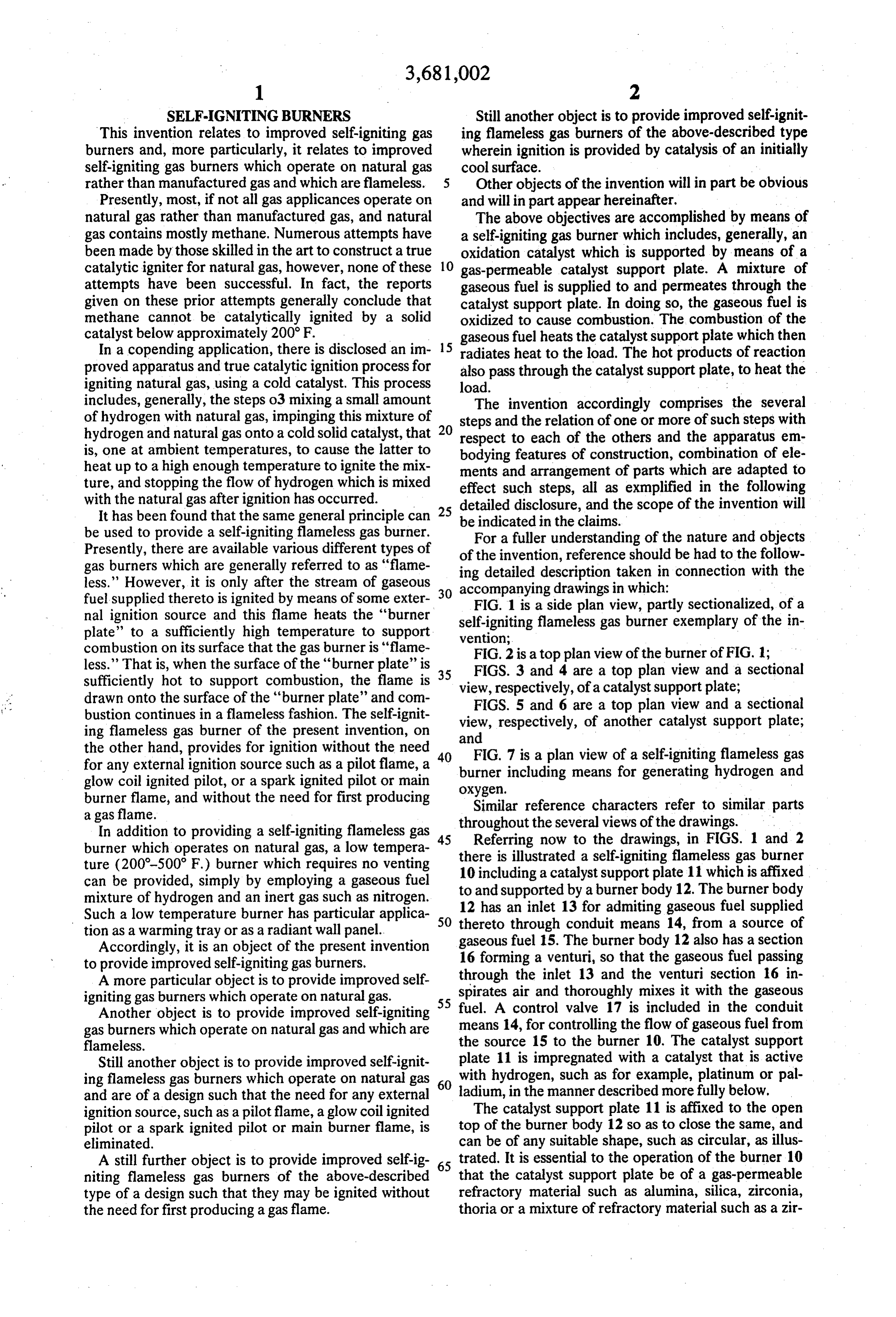
Another object is to provide improved self-igniting gas burners which operate on natural gas and which are the means 14, for controlling the flow of gaseous fuel from flameless. source 15 to the burner 10. The catalyst support Still another object is to provide improved self-ignit plate 11 is impregnated with a catalyst that is active ing flameless gas burners which operate on natural gas 60 with hydrogen, such as for example, platinum or pal and are of a design such that the need for any external ladium, in the manner described more fully below. ignition source, such as a pilot flame, a glow coil ignited The catalyst support plate 11 is affixed to the open pilot or a spark ignited pilot or main burner flame, is top of the burner body 12 so as to close the same, and eliminated. can be of any suitable shape, such as circular, as illus A still further object is to provide improved self-ig 65 trated. It is essential to the operation of the burner 10 niting flameless gas burners of the above-described that the catalyst support plate be of a gas-permeable type of a design such that they may be ignited without refractory material such as alumina, silica, zirconia, the need for first producing a gas flame. thoria or a mixture of refractory material such as a zir
Page 4
con mullite composition, so that the mixture of gaseous The burner 10 also can be operated as a low tem fuel can permeate through it. perature in a range of 200-500 F., burner simply by The source of gaseous fuel 15, in accordance with a providing a source of gaseous fuel comprising a mixture first embodiment of the invention, is a mixture of natu of hydrogen and an inert gas such as nitrogen. A burner ral gas and hydrogen, the latter being necessary to pro 5 of this type has the same advantages as the above vide the self-igniting character to the burner 10. described high temperature burner and, in addition, of Hydrogen can be used as the sole fuel, however, it fers the advantage of a controlled low temperature presents at least two disadvantages: (1) it has a low burner as well as the further advantage that no venting heating value, and thus it is difficult to get the catalyst O is required since the only combustion product is water support plate 11 sufficiently hot and (2) when the rate vapor. Such a burner therefore is particularly applica of flow of hydrogen is altered, an explosive range ble for use as a warming tray, or a radiant wall panel. resulting in "flashback' is encountered. Accordingly, it Normally, the load is supported atop the burner 10 is necessary to use a mixture of natural gas and canmeans by
such as a grate or the like, however, the load seated directly on the catalyst support plate. In hydrogen to eliminate this undesirable feature. In par 15 some applications, particularly with the low tempera ticular, if the natural gas is methane, a mixture contain ture burner, a catalyst support plate such as the catalyst ing at least 30 percent hydrogen is critical to obtain ig support plate 20 shown in FIGS. 3 and 4 can be pro nition and less than 70 percent hydrogen is critical to vided. This catalyst support avoid flashback. If butane, propane or other combusti parallel, recessed grooves 21 plate 20 has a number of ble gas is used the percentage of hydrogen in the mix and only the bottom walls 22 (FIG. 4) inofits formed top surface, the grooves 21 ture is appropriately adjusted to assure ignition and to are impregnated with the catalyst. Also, the top surface avoid flashback. of the catalyst support plate 20 with the exception of When the control valve 17 is operated to permit the area defined by the bottom walls 22 preferably is natural gas to flow from the source 15 to the burner 10, 25 sealed in an appropriate manner, to prevent the gase the natural gas flowing through the inlet 13 inspirates ous fuel from permeating through it and escaping to the air and the latter is thoroughly mixed with the natural atmosphere.
gas as it passes through the venturi section 16. As this Alternatively, a catalyst support plate 30 having a mixture of gaseous fuel impinges on the underside of number of support pins 31 extending through it, as il the catalyst support plate 11, the hydrogen reacts with 30 lustrated in FIGS. 5 and 6, can be provided. In this the catalyst impregnated in the catalyst support plate case, the support pins 31 project beyond the top sur 11 and generates heat. As the catalyst support plate 11 face of the catalyst support plate, and form a support gets hot, the natural gas also reacts on the catalyst sup for the load. While only a number of individual pins 31 port plate and the latter is rapidly heated. The catalyst are illustrated, it will be appreciated that a number of support plate 11 can be completely impregnated with 35 these pins can form a support for a grill or grate above the catalyst, in which case, combustion will occur on its the top surface of the catalyst support plate 30. underside. The catalyst support plate 11 will glow red In FIG. 7, there is shown a self-igniting flameless gas hot when the burner 10 is operating at its maximum burner 40 which is fueled with natural gas (methane) fuel input so that its operation can be visibly observed. from a source generally found in the home and el However, at lower temperature ranges, this glow may 40 sewhere, and which includes an electrolytic cell 41 for not be observed, since combustion occurs on the un generating hydrogen and oxygen. This hydrogen and derside of the catalyst support plate 11. oxygen is used to initiate combustion in the manner In many cases, it is preferable to have combustion described below.
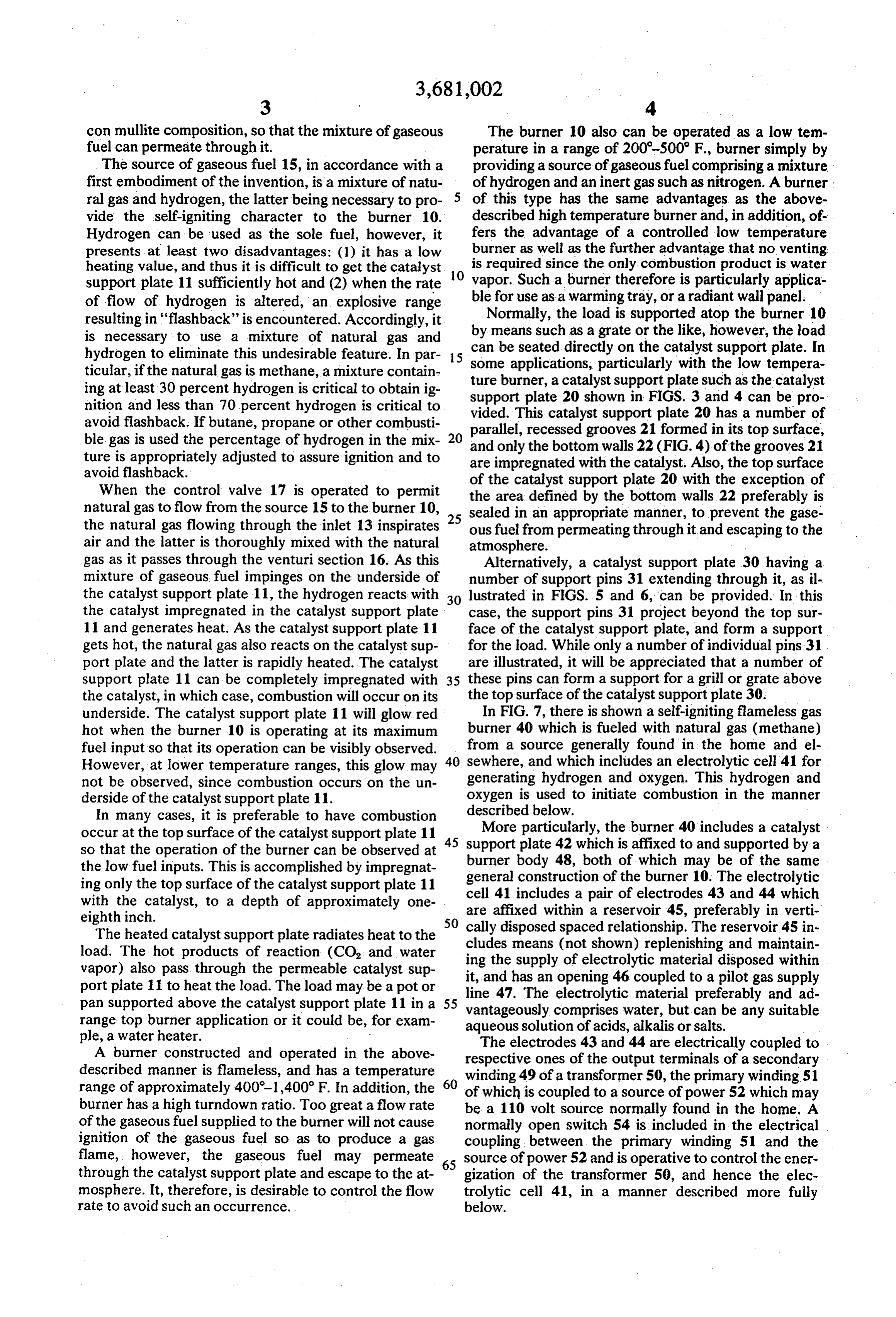
More particularly, the burner 40 includes a catalyst occur at the top surface of the catalyst support plate 11 45 support so that the operation of the burner can be observed at plate 42 which is affixed to and supported by a burner body 48, both of which may be of the same the low fuel inputs. This is accomplished by impregnat general construction of the burner 10. The electrolytic ing only the top surface of the catalyst support plate 11 cell 41 includes with the catalyst, to a depth of approximately one are affixed withina pair of electrodes 43 and 44 which a reservoir 45, preferably in verti eighth inch. 50 cally disposed spaced relationship. The reservoir 45 in The heated catalyst support plate radiates heat to the cludes load. The hot products of reaction (CO, and water ing the means (not shown) replenishing and maintain supply of electrolytic material disposed within vapor) also pass through the permeable catalyst sup it, and has an opening 46 coupled to a pilot gas supply port plate 11 to heat the load. The load may be a pot or pan supported above the catalyst support plate 11 in a 55 line 47. The electrolytic material preferably and ad vantageously comprises water, but can be any suitable range top burner application or it could be, for exam aqueous solution of acids, alkalis or salts. ple, a water heater. w The electrodes 43 and 44 are electrically coupled to A burner constructed and operated in the above respective ones of the output terminals of a secondary described manner is flameless, and has a temperature winding 49 of a transformer 50, the primary winding 51 range of approximately 400-1,400 F. In addition, the 60 of which is coupled to a source of power 52 which may burner has a high turndown ratio. Too great a flow rate be a 110 volt source normally found in the home. A of the gaseous fuel supplied to the burner will not cause normally open switch 54 is included in the electrical ignition of the gaseous fuel so as to produce a gas coupling between the primary winding 51 and the flame, however, the gaseous fuel may permeate 65 source of power 52 and is operative to control the ener through the catalyst support plate and escape to the at gization of the transformer 50, and hence the elec mosphere. It, therefore, is desirable to control the flow trolytic cell 41, in a manner described more fully rate to avoid such an occurrence. below.
Page 5
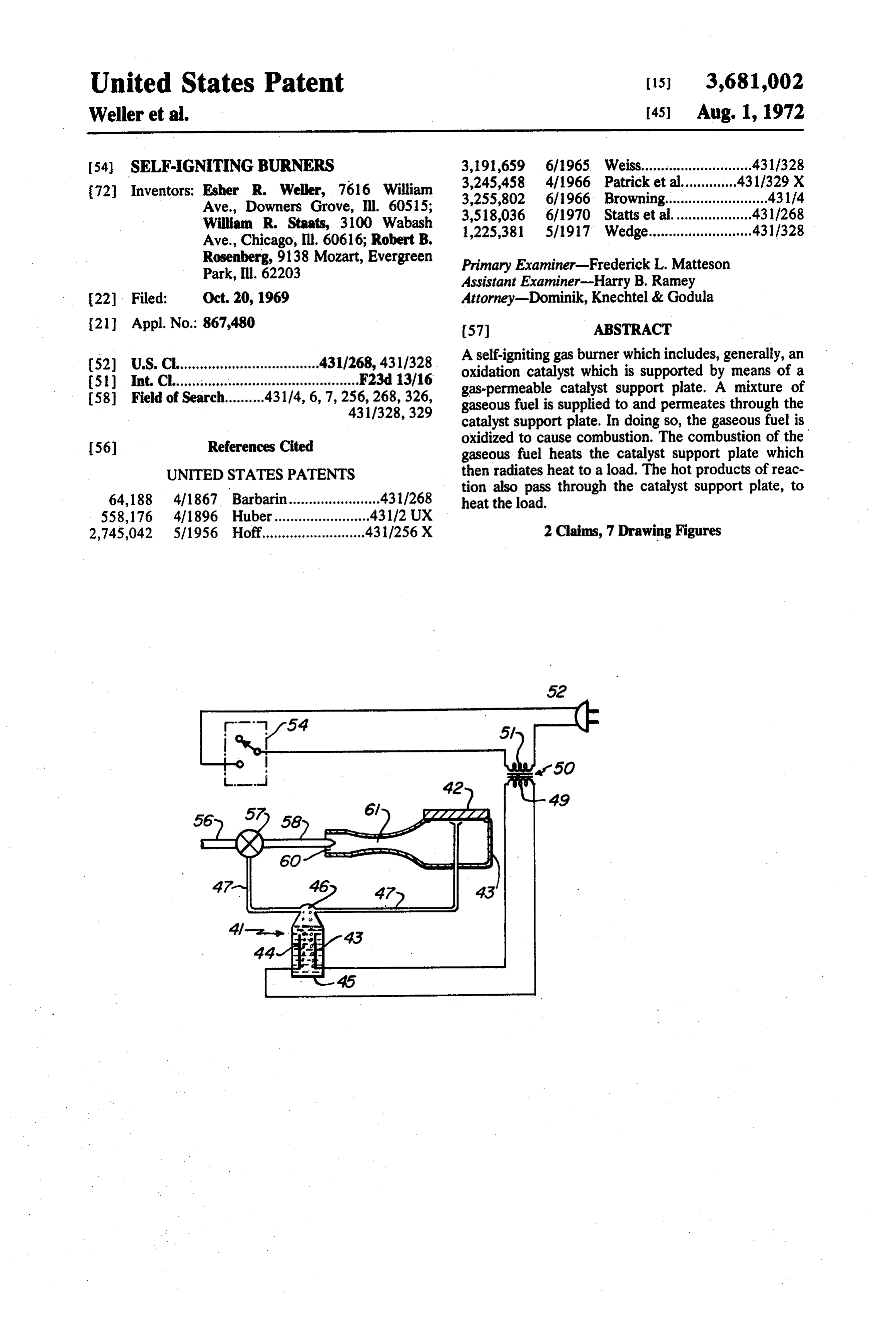
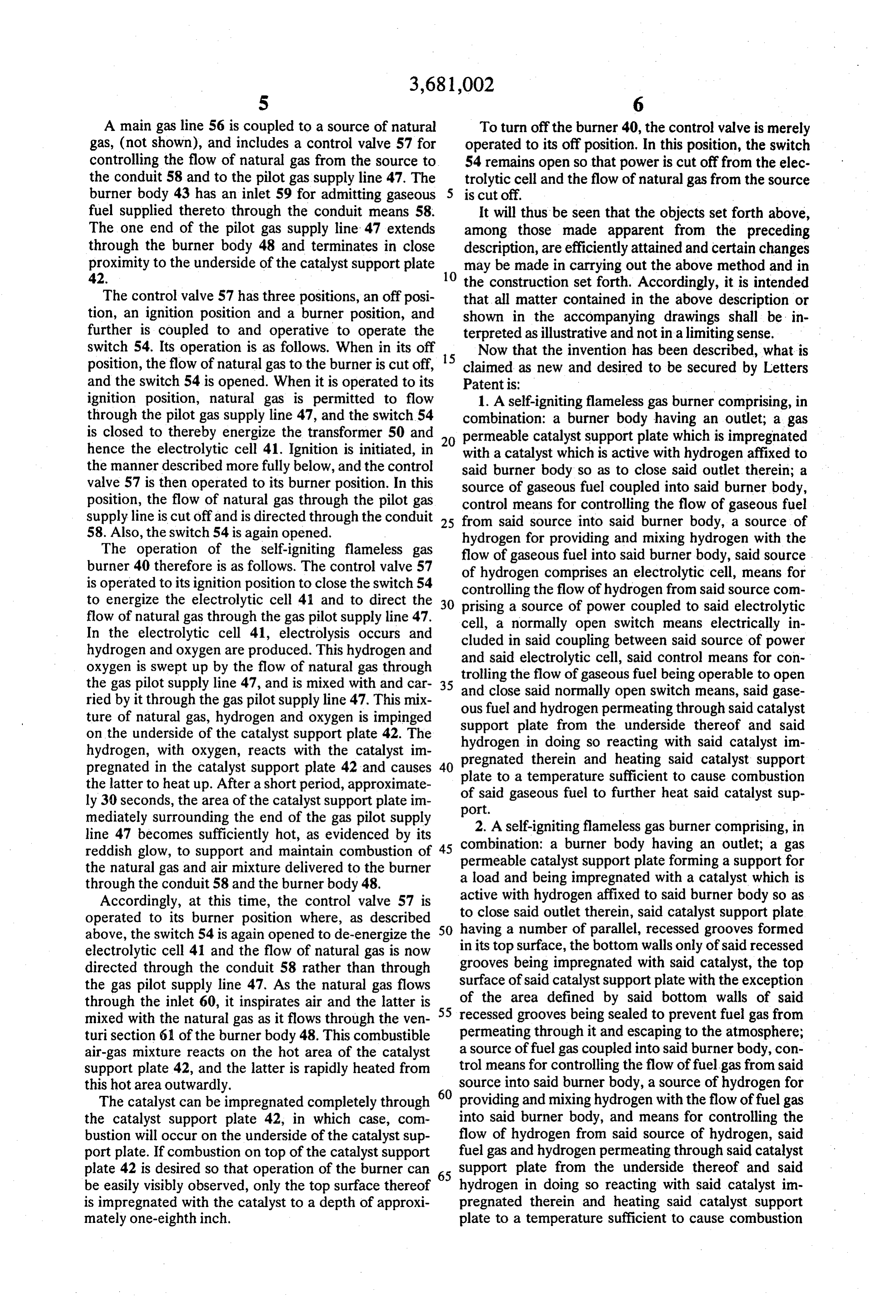
A main gas line 56 is coupled to a source of natural To turn off the burner 40, the control valve is merely gas, (not shown), and includes a control valve 57 for operated to its off position. In this position, the switch controlling the flow of natural gas from the source to 54 remains open so that power is cut off from the elec the conduit 58 and to the pilot gas supply line 47. The trolytic cell and the flow of natural gas from the source burner body 43 has an inlet 59 for admitting gaseous 5 is cut off.
fuel supplied thereto through the conduit means 58. It will thus be seen that the objects set forth above, The one end of the pilot gas supply line 47 extends among those made apparent from the preceding through the burner body 48 and terminates in close description, are efficiently attained and certain changes proximity to the underside of the catalyst support plate may be made in carrying out the above method and in
the construction set forth. Accordingly, it is intended
The control valve 57 has three positions, an off posi that all matter contained in the above description or tion, an ignition position and a burner position, and shown in the accompanying drawings shall be in further is coupled to and operative to operate the terpreted as illustrative and not in a limiting sense. switch 54. Its operation is as follows. When in its off 15 Now that the invention has been described, what is position, the flow of natural gas to the burner is cut off, claimed as new and desired to be secured by Letters and the switch 54 is opened. When it is operated to its Patentis:
ignition position, natural gas is permitted to flow 1. A self-igniting flameless gas burner comprising, in through the pilot gas supply line 47, and the switch 54 combination: a burner body having an outlet; a gas is closed to thereby energize the transformer 50 and 20 permeable catalyst support plate which is impregnated hence the electrolytic cell 41. Ignition is initiated, in with a catalyst which is active with hydrogen affixed to the manner described more fully below, and the control said burner body so as to close said outlet therein; a valve 57 is then operated to its burner position. In this source of gaseous fuel coupled into said burner body, position, the flow of natural gas through the pilot gas control means for controlling the flow of gaseous fuel supply line is cut off and is directed through the conduit 25 from said source into said burner body, a source of 58. Also, the switch 54 is again opened. hydrogen for providing and mixing hydrogen with the The operation of the self-igniting flameless gas flow of gaseous fuel into said burner body, said source burner 40 therefore is as follows. The control valve 57 of hydrogen comprises an electrolytic cell, means for is operated to its ignition position to close the switch 54 controlling the flow of hydrogen from said source com to energize the electrolytic cell 41 and to direct the 30 prising a source of power coupled to said electrolytic flow of natural gas through the gas pilot supply line 47. cell, a normally open switch means electrically in In the electrolytic cell 41, electrolysis occurs and cluded in said coupling between said source of power hydrogen and oxygen are produced. This hydrogen and and said electrolytic cell, said control means for con oxygen is swept up by the flow of natural gas through trolling the gas pilot supply line 47, and is mixed with and car 35 and closethesaid flow of gaseous fuel being operable to open normally open switch means, said gase ried by it through the gas pilot supply line 47. This mix ous fuel and hydrogen permeating through said catalyst ture of natural gas, hydrogen and oxygen is impinged support plate from the underside thereof and said on the underside of the catalyst support plate 42. The hydrogen in doing so reacting hydrogen, with oxygen, reacts with the catalyst im pregnated therein and heating with said said catalyst im catalyst support pregnated in the catalyst support plate 42 and causes 40 plate to a temperature sufficient to cause combustion the latter to heat up. After a short period, approximate of said gaseous fuel to further heat said catalyst sup ly 30 seconds, the area of the catalyst support plate im port.
mediately surrounding the end of the gas pilot supply 2. A self-igniting flameless gas burner comprising, in line 47 becomes sufficiently hot, as evidenced by its combination: a burner body having an outlet; a gas
reddish glow, to support and maintain combustion of permeable catalyst the natural gas and air mixture delivered to the burner a load and being impregnated support plate forming a support for through the conduit 58 and the burner body 48. with a catalyst which is Accordingly, at this time, the control valve 57 is active with hydrogen affixed to said burner body so as operated to its burner position where, as described to close said outlet therein, said catalyst support plate above, the switch 54 is again opened to de-energize the 50 having a number of parallel, recessed grooves formed electrolytic cell 41 and the flow of natural gas is now grooves in its top surface, the bottom walls only of said recessed directed through the conduit 58 rather than through surface ofbeing said impregnated with said catalyst, the top catalyst support plate with the exception the gas pilot supply line 47. As the natural gas flows through the inlet 60, it inspirates air and the latter is 55 of the area defined by said bottom walls of said mixed with the natural gas as it flows through the ven recessed grooves being sealed to prevent fuel gas from turi section 61 of the burner body 48. This combustible permeating through it and escaping to the atmosphere; air-gas mixture reacts on the hot area of the catalyst a source of fuel gas coupled into said burner body, con support plate 42, and the latter is rapidly heated from trol means for controlling the flow of fuel gas from said this hot area outwardly. source into said burner body, a source of hydrogen for The catalyst can be impregnated completely through 60 providing and mixing hydrogen with the flow of fuel gas the catalyst support plate 42, in which case, com into said burner body, and means for controlling the bustion will occur on the underside of the catalyst sup flow of hydrogen from said source of hydrogen, said port plate. If combustion on top of the catalyst support fuel gas and hydrogen permeating through said catalyst plate 42 is desired so that operation of the burner can 65 support plate from the underside thereof and said be easily visibly observed, only the top surface thereof hydrogen in doing so reacting with said catalyst im is impregnated with the catalyst to a depth of approxi pregnated therein and heating said catalyst support mately one-eighth inch. plate to a temperature sufficient to cause combustion
Page 6
of said fuel gas to further heat said catalyst support, whereby combustion of said fuel gas is initiated without the need of any external ignition source and without the need for producing aflame.

Page 7
UNITED STATES PATENT OFFICE
CERTIFICATE OF CORRECTION
Esher R. Kweller, William R. Staats, Robert B. Rosenberg
It is certified that error appears in the above-identified patent and that said Letters Patent are hereby corrected as shown below: The name of the first-listed inventor is incorrectly spelled. It should be "Esher R. Kweller".
The assignee of record is not listed in the patent. According to the Assignment document recorded in the Patent Office on May l9, l972, Reel 285l, Frame 053, the assignee is as follows: --Assignee: The Institute of Gas Technology, Chicago, Illinois-- (a not-for-profit corporation)
Signed and sealed this 23rd day of January 1973.
(SEAL)
Attest :
EDWARD M. FLETCHER, JR. ROBERT GOTTSCHALK Attesting Officer Commissioner of Patents
ForM PO-1050 (10-69) UsCOMMad C 60376-89 U.S. Gower NMEN PRNTENG OFF ce: 969 O-366-334
Provenance
- Collection
- Cited prior art
- Original PDF
- patentimages.storage.googleapis.com →
- Filed
- 1969-10-20
- Pages
- 7
- Method
- pdftotext (the PDF's own text layer) + pdftoppm 300dpi page scans
- Source
- Google Patents bibliographic record
- Granted
- 1972-08-01
- Inventors
- Esher R Weller; William R Staats; Robert B Rosenberg; ESHER R WELLER; ROBERT B ROSENBERG; WILLIAM R STAATS
- Transcribed from
- patentimages.storage.googleapis.com →