patent · US5251601
Lean burn mixture control system
12 October 1993
Page 1 — bibliographic record
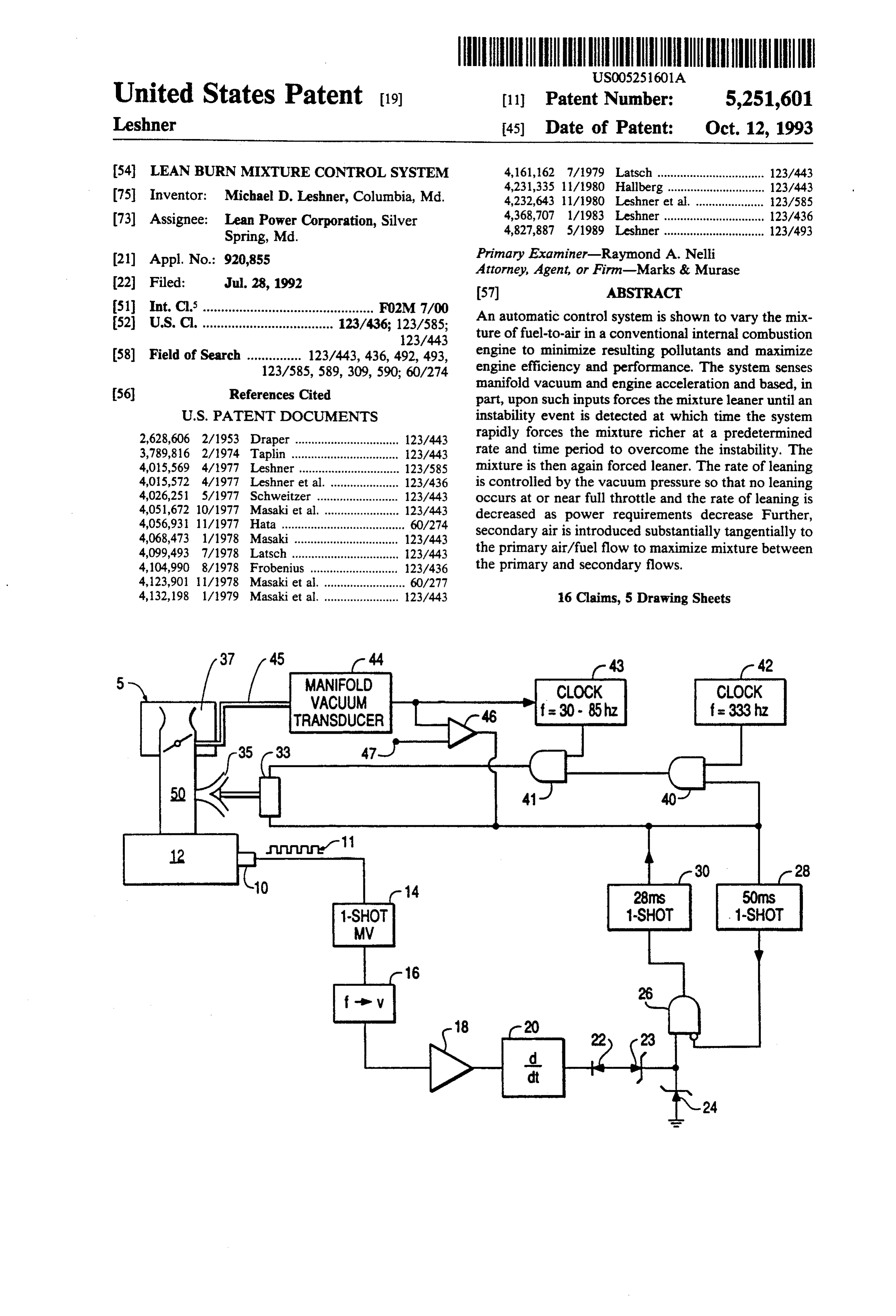
United States Patent (19) 11 Patent Number: 5,251,601 Leshner 45) Date of Patent: Oct. 12, 1993 54 LEAN BURN MIXTURE CONTROL SYSTEM 4,161,162 7/1979 Latsch ................................. 123/443 O 4,231,335 l/1980 Hallberg........... ... 123/443 75 Inventor: Michael D. Leshner, Columbia, Md. 4,232,643 11/1980 Leshner et al. .. ... 23/585 s 4,368,707 1/1983 Leshner ............ ... 123/436 73) Assignee: sy Corporation, Silver 4,827,887 5/1989 Leshner ............................... 123/493 Primary Examiner-Raymond A. Nelli (21) Appl. No.: 920,855 Attorney, Agent, or Firm-Marks & Murase 22 Filed: Jul. 28, 1992 (57) ABSTRACT
52 U.S. Cl. .................................... 123/436; 123/585;
An automatic control system is shown to vary the mix 123/443 ture of fuel-to-air in a conventional internal combustion 58) Field of Search ............... 123/443,436,949 engine to minimize resulting pollutants and maximize 123/585, 589, 309, 590. 60/24 engine efficiency and performance. The system senses manifold vacuum and engine acceleration and based, in (56) References Cited part, upon such inputs forces the mixture leaner until an
2,628,606 2/1953 Draper ................................ 123/443 rapidly forces the mixture richer at a predetermined 3,789,816 2/1974 Taplin ................................. 123/443 rate and time period to overcome the instability. The 4,05,569 4/1977 Leshner ............................... 123/585 mixture is then again forced leaner. The rate of leaning 4,015,572 4/1977 Leshner et al. ..................... 123/436 is controlled by the vacuum pressure so that no leaning 4,026,251 5/1977 Schweitzer . . 123/443 occurs at or near full throttle and the rate of leaning is 4,051,672 10/1977 Masaki et al. . . 123/443 decreased as power requirements decrease Further, 4,056,931 11/1977 Hata ...................................... 60/274 secondary air is introduced substantially tangentially to 4,068,473 1/1978 Masaki ................................ 123/443 4,099,493 7/1978 Latsch ................................. 23/443 the primary air/fuel flow to maximize mixture between 4,104,990 8/1978 Frobenius ........................... 23/436 the primary and secondary flows.
4,123,901 1 1/1978 Masaki et al. ......................... 60/277 4,132,198 1/1979 Masaki et al. ....................... 123/443 16 Claims, 5 Drawing Sheets
MANIFOLD
WACUUM
TRANSDUCER
Page 2
Drawing sheet — no readable text.
Page 3
Drawing sheet — no readable text.
Page 4
Drawing sheet — no readable text.
Page 5
Drawing sheet — no readable text.
Page 6
Drawing sheet — no readable text.
Page 7
invention. The rapid "jump' response in the rich direc
LEAN BURN MIXTURE CONTROL SYSTEM tion minimizes the occurrences of overly-lean mixtures.
FIELD OF THE INVENTION
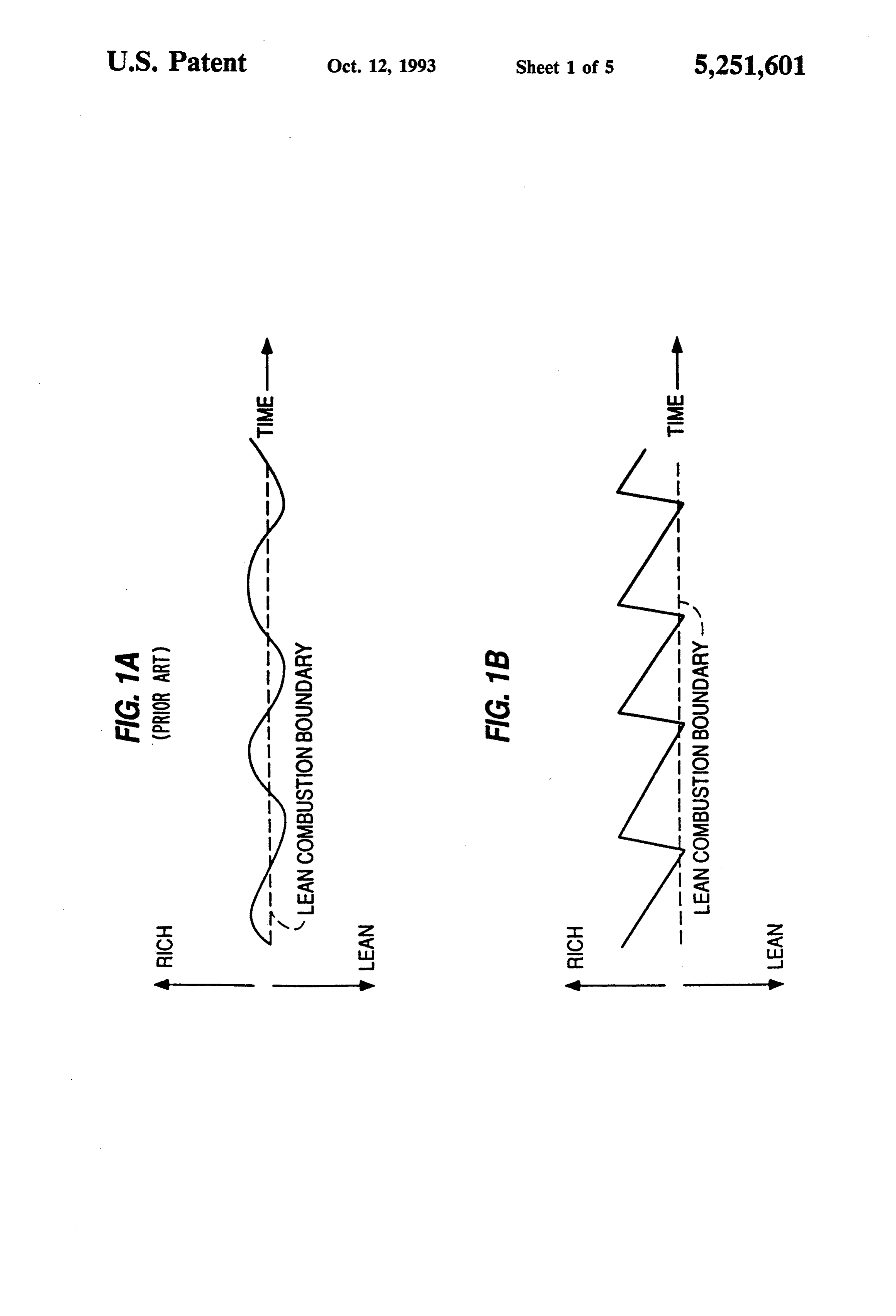
Further, the fast response in the lean direction keeps the mixture near the lean combustion boundary Thus, the
The present invention relates to a control system to 5 present invention produces a "sawtooth' relationship regulate automatically the ratio of air-to-fuel in an inter for the fuel/air mixture over time. In the "sawtooth' nal combustion engine to maintain a lean burn mixture example, the control system follows the Lean Combus based, in part, upon the rate of change of engine speed tion Boundary, without producing "overlean' combus and manifold vacuum levels. Secondary air is intro tion.
duced tangentially to the primary air flow to maximize In U.S. Pat. Nos. 3,789,816 to Taplin; 4,099,493 to mixing Latsch; and 4,104,990 to Frobenius, the system response BACKGROUND OF THE INVENTION is limited by the sampling technique. A portion of one engine revolution must be sampled and compared with
It is well known in the art that lean fuel/air mixtures a reference before a control decision is made. This time may be used advantageously to produce relatively low limitation slows down the overall system response. levels of exhaust emissions and relatively low fuel con In the previous Leshner patents-including U.S. Pat. sumption. However, drivability often suffers when lean Nos. 4,015,569; 4,015,572; 4,232,643; 4,368,707; and mixtures are employed, because mixtures which are 4,827,887-a final control element (the stepper motor) slightly "too lean' result in a markedly increased inci receives signals from a clock with instructions to step dence of combustion instability. Combustion instability 20 leaner at a predetermined rate, and another instruction results in poor drivability and increased emission of to step richer each time a weak combustion event is hydrocarbons. detected. For example, the abstract of U.S. Pat. No. A measurement of engine acceleration has been 4,368,707 specifies:
shown to be a reliable source of information regarding "The clock frequency thus sets the equilibrium rate combustion instability. Engine acceleration may be 25 of weak combustion events, defining the optimal measured by monitoring changes in the speed of the mixture to be supplied to the engine.' engine, or by measuring the motion of the engine. Fur These patents teach a method of subtracting two ther, it has been shown that control systems may be opposing signals, and effecting a response which corre constructed which continuously urge the fuel/air mix sponds to the difference ture leaner, until an indication of "over-leanness' (com- 30 control strategy creates abetween these signals. This bustion instability) is detected at which time the mixture over-lean much of the time, resulting inwhich mixture is slightly degraded driva is urged richer. However, these systems require the bility and hydrocarbon emissions.
mixture to be over lean for a period of time before the The new invention allows a bias toward the rich side mixture responds to the enrichening.
Control systems for automobile engines must be espe- 35 of the boundary of lean drivability, without dwelling cially fast and accurate to provide the correct quantities excessively on the lean side of the boundary By rapidly of fuel and air at each moment in time, while the engine "jumping back' each time "over-lean" combustion is experiences rapid changes in throttle position, speed, detected, the control system keeps a nominal margin and load The ability of a control system to quickly from the edge of over-lean drivability. This control adjust its mixture based on changes in operating condi- 40 scheme allows the response of the servo to be increased, tions is characterized as overall system response There while minimizing the tendency for "overshooting' into fore, a need exists to minimize the response time for a the over-lean regime during transient operation. lean burn mixture control system. The advantages of this invention over the prior art SUMMARY OF THE INVENTION are reduced hydrocarbon emissions and improved driv 45 ability. This result is derived from the improved speed
In this invention, the correction provided by the of response of the control system, made possible by control system in response to an indication of "over faster corrections in the rich direction. This invention is lean' combustion is very rapid. Mixture changes in the particularly useful in mobile applications such as auto "lean' direction are made relatively smoothly, while mobiles, to effect the optimum tradeoff among the fol corrections in the "rich' direction are made in rapid 50 lowing four variables:
"jumps." This correction process is performed without Harmful exhaust emissions (HC, CO, NO) any time delay for such things as subtractions, compari Fuel consumption sons, integration, etc. The process of initiating rapid Drivability (degree to which power is smooth and step-function mixture corrections immediately follow responsive) ing the detection of an unstable combustion event pro- 55 Cost vides a significant improvement over the prior art in BRIEF DESCRIPTION OF THE DRAWINGS overall system response.
Therefore, it is an object of this invention to provide FIG. 1A is a graphic representation of the mixture faster system response, so that the optimum fuel/air versus time for control systems employing relatively mixture may be supplied at all times-even through 60 equal response speeds in the rich and lean directions as changes in operating conditions-without suffering shown in the prior art.
combustion instability. FIG. 1B is a graphic representation of the mixture FIG. 1A shows changes in the mixture over time for versus time for the control system of the present inven control systems using equal response speeds in both the tion.
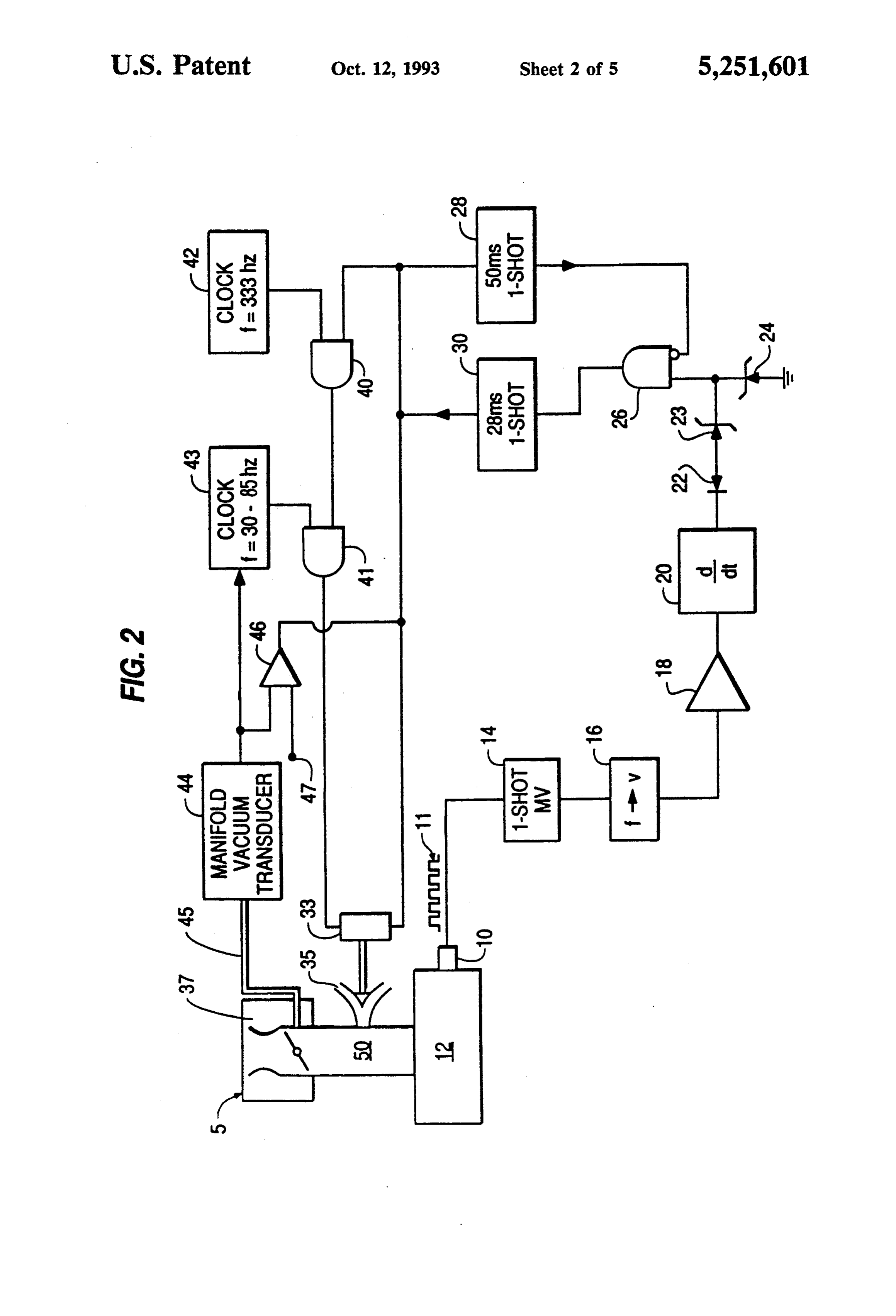
rich and lean directions. As shown in FIG. IA, the 65 FIG. 2 is a logic diagram of the lean burn mixture mixture resides below the Lean Combustion Boundary control system of FIG. 1B.
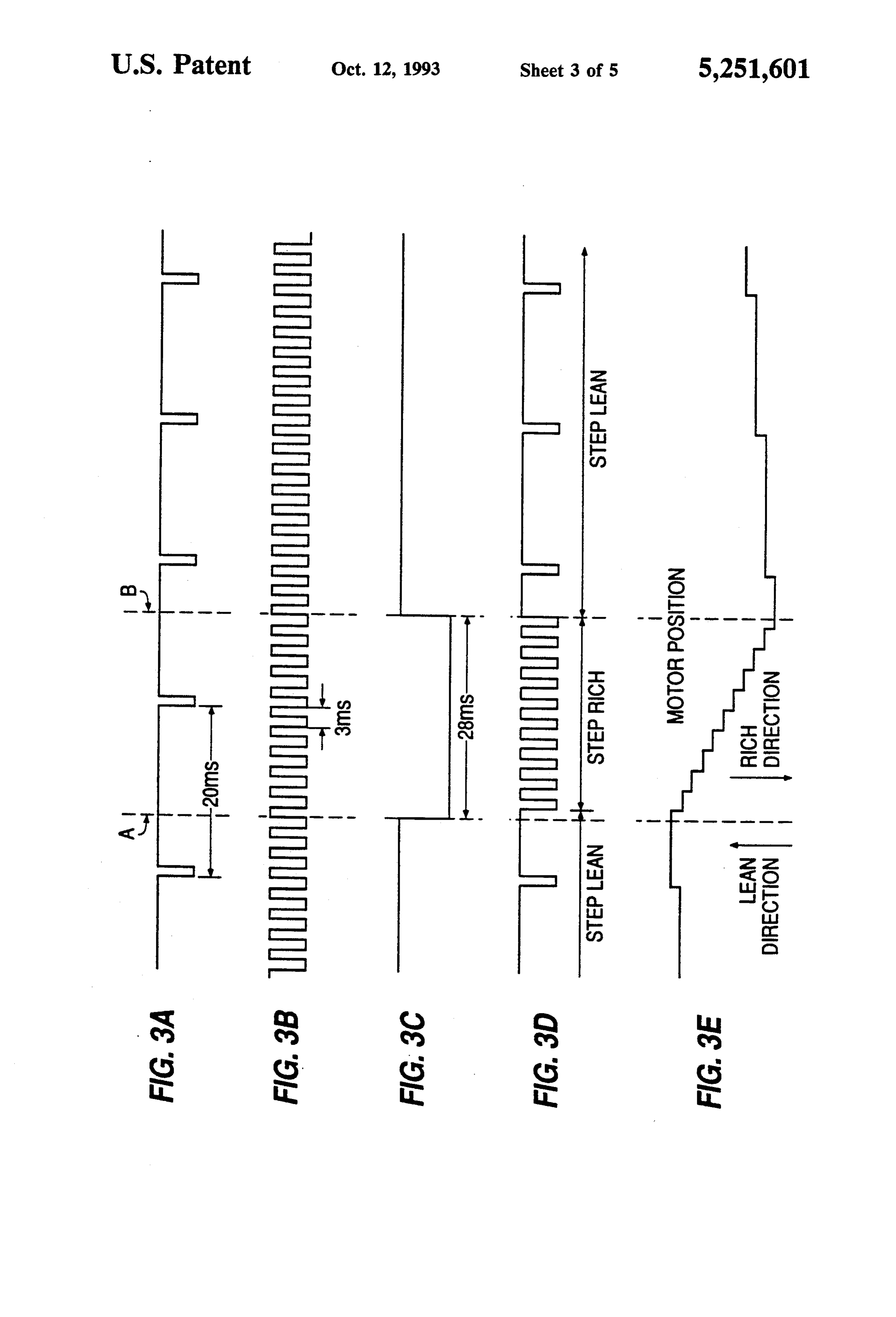
for a period of time FIG. 1B shows changes in the mix FIG. 3A is a graphic representation of the output of ture over time for the control system of the present the variable clock of the system of FIG. 1B.
Page 8
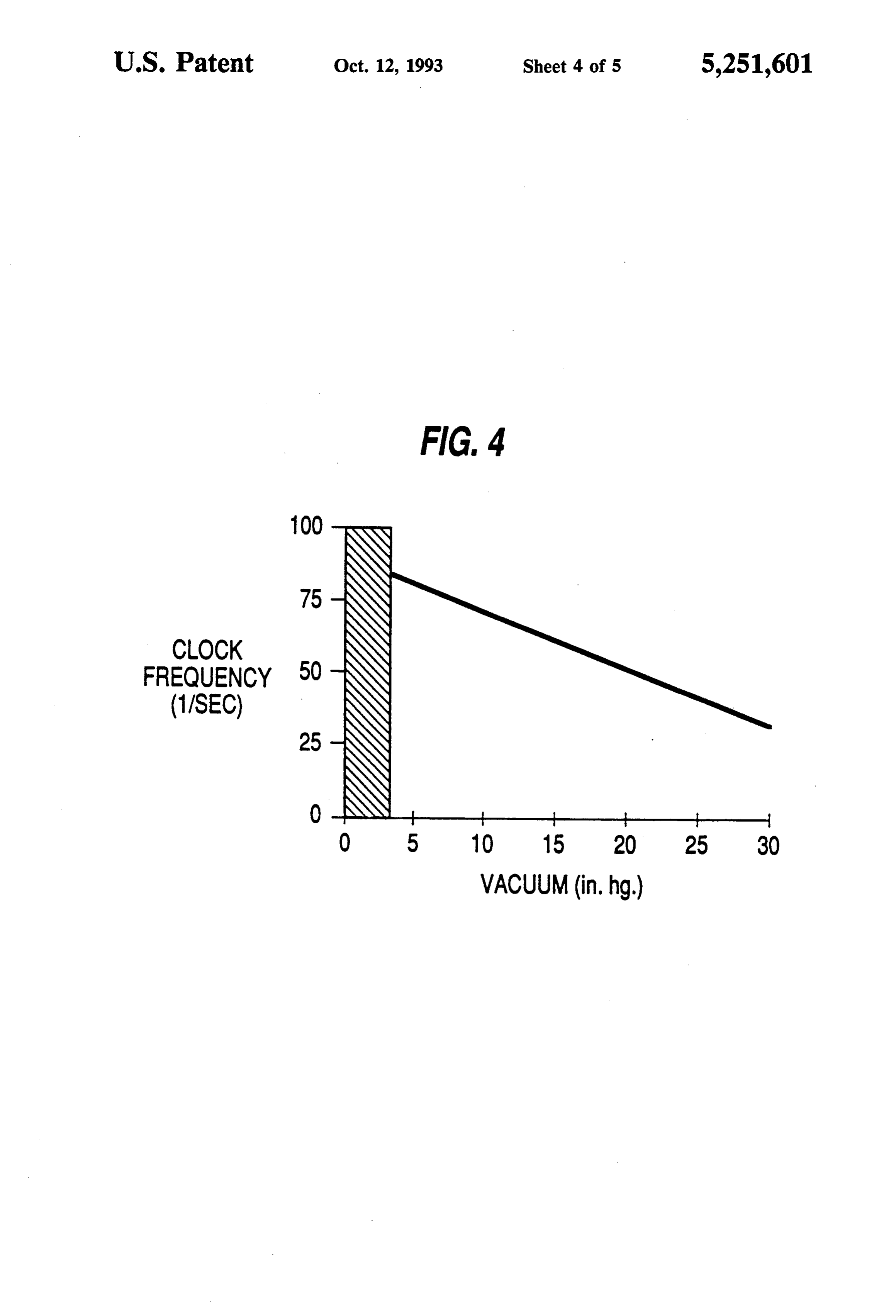
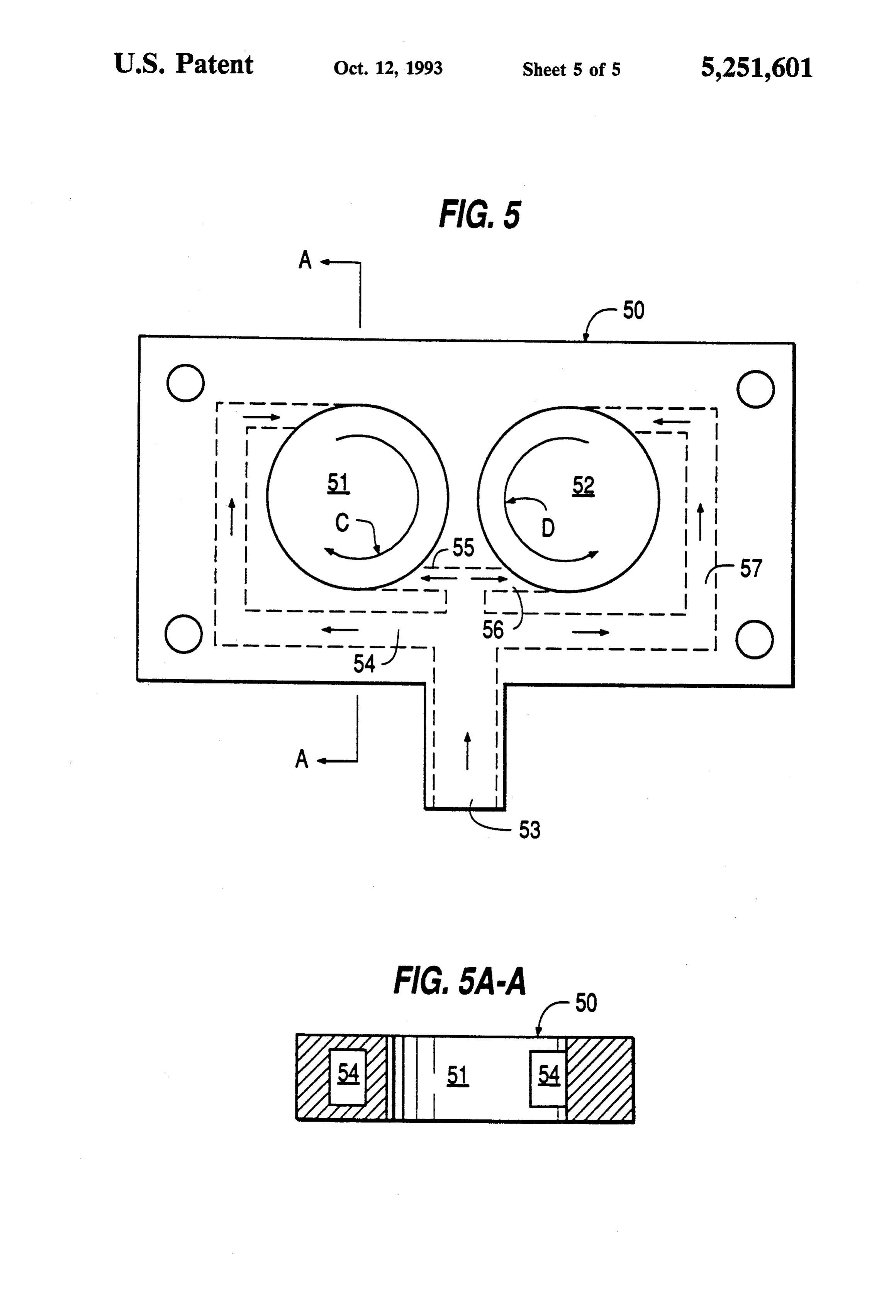
FIG. 3B is a graphic representation of the output of passes only negative going changes in the speed of the the fixed frequency clock of the system of FIG. 1B. engine 12 which exceed a predetermined threshold, FIG. 3C is a graphic representation of the output of represented by the value of Zener diode 23. A clipper the first one-shot multi-vibrator of the system of FIG. such as Zener diode 24 is also provided consistent with 1B. 5 good circuitry practice.
FIG. 3D is a graphic representation of the output of When a weak combustion event is imminent in the an AND gate of the system of FIG. 1B. engine 12 because, for example, the mixture is too lean, FIG. 3E is a graphic representation of the position of it is desirable to detect and overcome the event by rap the stepping motor of the system of FIG. 1B. idly sending a richer mixture to the engine 12. Because FIG. 4 is a graphic representation of the frequency of 10 a weak combustion event results in the engine 12 decel the variable clock versus the vacuum level in the mani erating above a threshold minimum rate, the system 5 is fold of the system of FIG. 1B. designed to detect deceleration indicative of a weak FIG. 5 is a top view of the air-addition plate of the combustion event and send a correcting signal to step system of FIG. 1B. ping motor 33 to overcome the event. Thus, the diode FIG. SA-A is a cross section of the air-addition 15 22 and Zener diode 23 filter out signals except those plate of FIG. 5 taken along line A-A. signals which could indicate a weak combustion event DESCRIPTION OF A PREFERRED (i.e., negative going signals above a threshold level). EMBODIMENT How the system 5 responds to the detection of a weak combustion event will be discussed next.
FIG. 2 is a logic diagram for the lean burn control Signals from element 23 indicative of a weak combus system 5 of the present invention for a conventional tion event are passed on through an AND gate 26 to a spark ignition internal combustion engine 12. While 28 millisecond one-shot multi-vibrator 30. The one-shot engine 12 is described as a conventional spark ignition multi-vibrator 30 sends out a pulse of sufficient duration internal combustion engine, the invention is applicable (e.g., 28 milliseconds) to enable stepping motor 33 suffi to all types of internal combustion engines, including 25 cient time to respond to the event by creating a "richer' but not limited to, free-piston engines, turbines, and mixture and counteracting the weak combustion event. "Wankel' or rotary engines. Therefore, such terms as At the same time, the one-shot multi-vibrator 30 also "manifold," "carburetor," "air plate," and "throttle," puts out a 28 millisecond pulse which is fed back into a should be regarded as being used in the generic sense second one-shot multi-vibrator 28 which sends out a 50 regardless of the specific form which they may take in 30 millisecond pulse. The output of the one-shot multi a given application. The engine 12 includes a carburetor vibrator 28 enters the inverting input of the AND gate 37. An air valve 35 admits secondary or supplemental 26. This "loop' (multi-vibrator 30 to multi-vibrator 28 air into the engine 12 through an air-addition plate 50 to AND gate 26 back to multi-vibrator 30) disables between the throttle and the engine 12. A stepping one-shot multi-vibrator 30 from emitting a second pulse motor 33 controls the size of the opening of valve 35. 35 for at least 50 milliseconds following a first triggering of Thus, the stepping motor 33 adjusts the valve 35 either multi-vibrator 30. This ensures a minimum spacing be to increase the ratio of fuel-to-air (i.e., move in a rich tween output pulses from one-shot multi-vibrator 30 so direction) or to decrease the ratio of fuel-to-air (i.e., that-even in the case where a plurality of corrections move in a lean direction). are required-the correction pulses will have a mini FIG. 2 shows a means to detect the direction and rate mum spacing of 50 milliseconds. of change of the speed of the engine 12. A transducer 10 The reason for this spacing is that when a correction (in the preferred embodiment the transducer 10 is of a is required in the engine 12, the corrected mixture (i.e., magnetic pick-up type or variable inductance magnetic richer mixture to overcome the event) must be drawn pick-up type) is placed in close proximity to a flywheel into the engine 12, compressed, ignited and expanded. ring gear which is fixed to the crank shaft of the engine 45 This takes time. Accordingly, one would not expect to 12 and by its placement the transducer 10 detects the see the result of a given correction for approximately passing of the flywheel gear teeth. Next to transducer one or two revolutions of the engine 12, which corre 10 in FIG. 2 is a representation of the pulse train output sponds to the 50 milliseconds inhibition of a succeeding signal 11 from transducer 10. Thus, the frequency of the correction. Thus, the 50 millisecond spacing provides pulses in pulse train 11 varies with the speed of engine SO the engine 12 sufficient time to respond to a correcting 12. pulse from multi-vibrator 30 before another correcting The pulse train signal 11 is processed by one-shot pulse, if necessary, can be generated. This minimizes the multi-vibrator 14 and then through tachometer 16 chance for overshooting or overcorrection by system 5. which converts the train of pulses 11 of varying fre Other time durations may be used, but for the preferred quencies into corresponding various voltages. Thus, the 55 embodiment the time pulses are 28 and 50 milliseconds voltage output of tachometer 16 varies with the speed for vibrators 30 and 28, respectively. of the engine 12. The 28 millisecond correction performs two other The voltage is then amplified by an operational am functions: It reverses the direction of the stepping plifier 18 and the resulting signal is sent to differentiat motor 33 so that the motor 33 travels in the direction ing circuit 20. Accordingly, the output of circuit 20 which enriches the mixture (i.e., closes the valve 35) reflects both the direction of the rate of change of speed and it changes the stepping frequency (or rate) to a of engine 12 (e.g., faster-to-slower, slower-to-faster or much higher frequency predetermined by clock 42 so no change of speed) and the amount of speed change that during the 28 millisecond pulse there are a rapid (e.g., the amount of acceleration or deceleration). number of steps in the rich direction to overcome the The signal from circuit 20 is sent to diode 22 which 65 event. The system 5 has a fixed frequency oscillator passes only signals from circuit 20 representing a nega clock 42 with a preferred frequency of 333 hertz. The tive rate of change in the speed of the engine 12 (i.e., the frequency of clock 42 determines the number of steps engine decelerating). The Zener diode 23, in turn, taken in the rich direction during the 28 millisecond
Page 9
correction period. The 333 hertz frequency equates to 3 FIG. 3A represents the output from the clock 43. milliseconds between pulses. Thus, each correction Although the output of the clock 43 is variable, in this totals 10 steps in the rich direction in the preferred example FIG. 3A shows a nominal output frequency of embodiment. 50 hertz resulting in approximately 20 milliseconds of System 5 automatically varies the rate at which the spacing between the "go lean" pulses. Thus, in its nomi mixture is forced lean during "nominal' operation (i.e., nal condition in this example the stepping motor 33 when no weak combustion event has been detected) in makes one step in the lean direction every 20 millisec order to maximize responsiveness and minimize pollut onds when there is no correction being commanded by ants at various performance levels, as discussed more the system 5.
fully below. Vacuum level signal 45 is generated by the 10 FIG. 3B represents the output of the fixed frequency engine 12 and reflects the power requirements of the clock 42 which, in the preferred embodiment, is 333 engine 12 in a generally inverse relation. For example, hertz resulting in approximately 3 milliseconds of spac at high power levels the vacuum pressure is low. The ing between the "go rich' pulses.
intake manifold vacuum transducer 44 receives a vac uum signal 45 from the engine 12 and outputs a signal 15 shotFIG. 3C represents the output signal of the first one multi-vibrator 30. When the signal is high, the which controls the frequency of the clock 43. Variable system 5 has not detected the existence of a weak con frequency oscillator clock 43 has a preferred frequency bustion. When a weak combustion event is detected by range of between 30 to 85 hertz. Changes to the fre the system 5, the signal from multi-vibrator 30 goes low quency of clock 43 are accomplished by feeding the for a period of 28 milliseconds.
voltage output of transducer 44 into the frequency de 20 termining input of clock 43. For example, as shown in ofFIG. AND 3D shows the shape of the signal at the output gate 41 which represents the composite signal
FIG.4, relatively high levels of intake manifold vacuum of AND gate would cause the clock 43 to run at about 30 hertz, while signal sent to 40 and multi-vibrator 30 and is the control the stepping motor 33.
relatively low manifold vacuum levels would cause the FIGS. 3A-D show that in the absence of a correction frequency to vary up to approximately 80 hertz. The 25 (i.e., while FIG. 3C is in its high state), pulses from the frequency of clock 43 determines the rate at which the stepping motor 33 will go lean when the system 5 is in clock 43 go to the motor 33 and the motor steps in the lean direction at the frequency of 50 hertz. Once a weak its nominal state. The higher the frequency of clock 43, combustion event is detected, a 28 millisecond correc the faster the stepping motor 33 steps and the faster the mixture goes lean. The frequency range of 30 to 85 30 tion is initiated. During the TM 28 millisecond correc hertz is by way of example and other ranges may be tion (shown in FIG. 3C) the direction of the steps of the used. Thus, the system 5 automatically matches the stepping motor 33 is reversed from go lean to go rich frequency of clock 43 to the power requirements of the and the frequency of the steps of the stepping motor 33 engine 12-based upon the level of manifold vacuum is increased as determined by the frequency of fixed 45-to maximize the performance of the engine 12 as 35 clock 42 (e.g., 333 hertz which equals one go rich step discussed below. every 3 milliseconds) for the duration of the 28 millisec The output of clocks 42 and 43 are sent to AND gates ond correction. After the 28 millisecond correction is 40 and 41, respectively. The AND gates 40 and 41 completed, the stepping rate and direction of the motor combine signals. The two signals that feed AND gate 40 33 reverts back to a rate of one go lean step every 20 are the 28 millisecond signal representing a weak com milliseconds, as shown in FIG. 3A. Thus, as shown in bustion event and the clock 42 frequency of 333 hertz. FIG. 3D, during the period before the correction is Thus, the output of AND gate 41 is a composite signal initiated (i.e., to the left of dashed line A), the motor 33 which is used to command the final control element is travelling in a lean direction (i.e., opening the valve stepping motor 33 to take a step. Specifically, whenever 35) and a frequency of 50 hertz. During the correction there is a pulse at the output of AND gate 41, the step 45 (i.e., between dashed lines A and B), the notor 33 is ping motor 33 takes one step. traveling more rapidly in the rich direction (i.e., closing In summary, the engine 12 has a carburetor 37. Sec the valve 35) at a frequency of 333 hertz. After the 28 ondary air enters carburetor 37 through valve 35 which millisecond correction has elapsed (i.e., to the right of is controlled by final control element stepping motor 33. line B), the motor 33 is travelling forward again opening In the absence of any detection of weak or unstable 50 the valve 35 and causing the mixture to become leaner combustion, stepping motor 33 is commanded to open again at the rate of 50 hertz.
the valve 35 in a lean direction at a rate set by clock 43 FIG. 3E shows the position of motor 33 in time rela and dependent upon the manifold vacuum pressure tionship with FIGS. 3A-D. As the first pulse in FIG. (e.g., a frequency of 30 to 85 hertz). Upon the detection 3D occurs it effects one step in the lean direction and of a weak combustion event, the final control element 55 the position of motor 33 moves one step in the lean stepping motor 33 is commanded to reverse direction direction (i.e., up the page) During the 28 millisecond and make a correction in the rich direction by closing correction, the motor 33 steps in the rich direction (i.e., valve 35 for a predetermined time period (e.g., 28 milli down the page) at a more rapid rate and, in this exam seconds) at a predetermined frequency step rate, deter ple, takes 10 steps in the rich direction during the 28 mined by clock 42 (e.g., a frequency of about 333 hertz) millisecond correction. Following that correction, the resulting in a predetermined number of "rich' steps system 5 detects no additional weak combustion events (e.g., 10 steps). and the motor 33 takes three steps in the lean direction, FIGS. 3A-E are shown in phase relationship to one at the rate of one step every 20 milliseconds. Thus, FIG. another. Dashed line A in FIGS. 3A-E reflects the 3E shows the motor 33 going lean, taking 10 quick steps point of time at which system 5 detects a weak combus 65 rich and then going lean again. FIG. 3E illustrates two tion event. Dashed line B in FIGS. 3A-E reflects the different rates of travel depending on whether the end of the correction time period (e.g., 28 milliseconds motor 33 is effecting a leaning or enrichening of the after dashed line A). fuel/air mixture.
Page 10
As noted above, the frequency output of clock 43 is FIG. 5 shows the air-addition plate 50 which is controlled by the intake manifold vacuum 45 to im mounted between the carburetor and the intake mani prove engine performance. FIG. 4 shows the relation fold of the engine 12 for the purpose of admitting sec ship between the signal from the vacuum transducer 45 ondary (e.g., supplementary) air into the engine 12 to and the frequency of clock 43. At very low levels of effect a leaner fuel-to-air mixture. The primary fuel/air vacuum (in this example, 0-3 inches of mercury) the mixture passes from the intake manifold through cylin power requirements on the engine 12 are very high and drical main passageways 51 and 52. Secondary air en the throttle is nearly fully open (shown as the shaded ters the plate 50 through entrance passageway 53. The region in FIG. 4). Under these conditions it is neither secondary air is then channeled to the passageways 51 desirable nor advantageous to use a lean mixture. Dur 10 and 52 through four secondary passageways 54, 55, 56 ing these very low vacuum levels, the valve 35 is caused and 57 shown in phantom line in FIG. 5. to stay closed. Specifically, the output voltage of trans The secondary passageways 54, 55, 56 and 57 are ducer 44 is connected to one input of comparator 46. constructed to produce a swirl in the main passageway Reference voltage 47 equals the voltage output from 15 51 and 52. More specifically, secondary air passages 54 transducer 44 when the vacuum pressure level 45 is 3 and 55 connect with cylindrical main passageway 51 inches of mercury and is connected to the second input tangential to the axis of cylindrical passageway 51. of comparator 46. The output of comparator 46 is con Thus, secondary air entering passageway 51 from Sec nected to the output of multi-vibrator 30 and is able to ondary passageways 54 and 55 will tend to swirl with override multi-vibrator 30. Thus, at low values of mani 20 the primary fuel/air mixture in passageway 51. This fold vacuum (e.g. between 0 and 3 inches of mercury), swirl will be in a generally clockwise direction in pas sageway 51 as shown by arrow C.
multi-vibrator 30 is overridden, and the stepping motor Similarly, secondary passageways 56 and 57 impart a 33 is caused to run continuously at 333 hertz in the counterclockwise swirl to the primary fuel/air mixture reverse direction, keeping valve 35 closed.
At power levels equaling vacuum levels in the 5-10 25 in FIG.
main passageway 52.
5A-A shows, in cross-section, the construc inches of mercury range, the throttle is substantially tion of plate 50. The entry of secondary passageway 54 open-but not fully open-and under these conditions to main passageway 51 is shown in FIG. 5A-A. The use the mixture is optimally quite lean for the purposes of of four secondary passageways is by way of example emission control and fuel economy. As shown in FIG. only and greater or fewer passageways may be used. 4, the relationship between the frequency of clock 43 30 The benefit of introducing the secondary and vacuum 45 changes in a substantially linear fashion gential to the primary flow is to maximize theflows tan mixture between about 5 inches and about 25 inches of mercury. of secondary air from passageways 54, 55, 56 and 57 At approximately 20 inches of mercury, the engine 12 with the primary mixtures in passageways 51 and 52. is experiencing a very low power condition and the Thus, by maximizing the mixtures of the primary and throttle is substantially closed. Under such conditions 35 secondary flows, the overall responsiveness of system 5 even slight irregularities in the combustion would be is improved.
easier to detect and, accordingly, a very lean mixture is While there has been illustrated and described a par undesirable. Thus, in this range, for reasons of improved ticular embodiment of the present invention, it will be drivability, the frequency of clock 43 is biased lower at appreciated that numerous changes and modifications high vacuum levels which, in turn, biases the fuel/air will occur to those skilled in the art and it is intended in ratio richer in the region of 15-20 inches of mercury, as the appended claims to cover all those changes and compared to the ratio of the mixture for the 5-10 inches modifications which fall within the scope of the present range. The vacuum levels specified are by way of exam invention.
ple only and other levels may be used. What is claimed as new and desired to be secured by In summary, it is generally desirable to bias the con 45 Letters Patent of the United States is: trol system richer or leaner, dependent on the intake 1. An engine having a control system for controlling manifold vacuum 45 in the engine 12 for the purpose of a valve means in said engine to alter the ratio of the improving drivability and reducing exhaust emissions. fuel/air mixture applied to said engine, comprising: When the throttle is fully open, the driver needs full means for controlling said valve means to alter said power and a lean mixture is undesirable. In this exam 50 ratio of the fuel/air of said mixture wherein said ple, when the vacuum is between 0-3 inches of mer controlling means generally is changing said ratio cury, the leaning function is disabled entirely. In the of said mixture at a first rate and in a leaner direc high-power regions where the throttle is not fully tion;
open-for example, the region of 5-10 inches of mer means for detecting the occurrence of deceleration in cury manifold vacuum -the leanest mixture that is 55 said engine above a set value indicative of a weak consistent with smooth engine operation is desirable. In combustion event, said detection means further the region of 15-20 inches of mercury which represents having means for generating a signal and sending very low power levels-the mixture should be biased said signal to said controlling means when said slightly richer because under these conditions the driver deceleration above said set value is detected; and may be able to detect weak combustion or unstable said controlling means, upon receipt of said signal, combustion more easily than at higher power levels. changing said ratio of said mixture at a second rate Thus, in the range of 3-25 inches of mercury manifold and in a richer direction for a predetermined period vacuum, the system biases the mixture slightly richer or of time, said second rate being faster than said first leaner by changing the frequency of clock 43. This rate, after which said period of time said control change in clock frequency 43 has the effect of tailoring 65 ling means again changes said ratio at said first rate the fuel-to-air mixture to the power level of the engine and in said leaner direction. 12 and effects a better tradeoff between exhaust emis 2. The engine of claim 1, wherein said controlling sions and drivability. means includes a stepping motor.
Page 11
3. The engine of claim 1, wherein said first rate is said frequency of said adjustable clock means being variable. controlled by the signal from said measuring means 4. The engine of claim 3, wherein said variable rate is to decrease gradually the frequency of said timing between 30 and 85 hertz. signals as the power requirement decreases; 5. The engine of claim 1, wherein said second rate is 5 wherein said first controlling means operates said fixed. ratio adjusting means to provide a very rich ratio to 6. The engine of claim 5, wherein said fixed rate is 333 said engine upon receipt of a signal form said mea hertz. suring means indicative of a power requirement 7. The engine of claim 1, wherein said period of time O above a first predetermined value, corresponding is 28 milliseconds. generally to said engine being operated at full 8. Means for altering the ratio of the fuel/air mixture throttle; and as set forth in claim 1, wherein a generally cylindrical further wherein said second controlling means, upon passageway means is provided to enable a thorough receipt of a signal from said measuring means indic ative of a power requirement below said first pre mixing of a primary fuel/air blend stream with a sec 15 determined value, operates said ratio adjusting ondary air in a multi-cylinder engine, wherein said gen means to provide a gradually richer ratio to said erally cylindrical passageway means provides said mix engine as said power requirement, and hence, the ing by moving said primary fuel/air blend stream frequency of said timing signals, decreases. through said generally cylindrical passageway means in 10. The engine of claim 9 wherein said measuring a coaxial direction, then applying said secondary air 20 means includes a means to detect a manifold vacuum generally tangentially to said coaxial direction of said pressure level in said engine which corresponds gener primary fuel/air blend stream through a tangential pas ally to the power requirements of said engine. Sageway means. 11. The engine of claim 10, wherein said first prede 9. An engine having a control system for controlling termined value corresponds to a vacuum pressure of the ratio of fuel/air mixture applied to said engine, com 25 approximately three inches of mercury. prising: 12. The engine of claim 10, wherein when said prede means for adjusting the ratio of fuel-to-air in said termined value correspond to a vacuum pressure of approximately ten inches of mercury, said frequency of engine;
said timing signals is approximately 65 pulses per sec first controlling means for controlling said ratio ad 30 ond.
justing means; 13. The engine of claim 10, wherein when said prede second controlling means for controlling said ratio termined value corresponds to a vacuum pressure of adjusting means, said second controlling means approximately 20 inches of mercury, said timing signal including an adjustable clock means to generate frequency is approximately 50 pulses per second. input timing signals at a preselected frequency 35 14. The engine of claim 10, wherein said measuring wherein the frequency of said input timing signals means includes a vacuum transducer.
may be varied; 15. The engine of claim 9, wherein said adjusting measuring means for measuring the power require means includes a stepping motor.
ments of said engine, said measuring means further 16. The engine of claim 9, wherein the relationship of including means for generating a signal of said said power requirement and said frequency is substan power requirements and sending said signal to said tially linear.
first and second controlling means; s: xx s: s: k
Provenance
- Collection
- Cited prior art
- Original PDF
- patentimages.storage.googleapis.com →
- Filed
- 1992-07-28
- Pages
- 11
- Method
- pdftotext (the PDF's own text layer) + pdftoppm 300dpi page scans
- Source
- Google Patents bibliographic record
- Granted
- 1993-10-12
- Inventors
- Michael D. Leshner; Lean Power Corp
- Transcribed from
- patentimages.storage.googleapis.com →