patent · US3969481
Process for generating ultra high purity H2 or O2
13 July 1976
Page 1 — bibliographic record
United States Patent 19 1, 3,969,481 Murray et al. (45) July 13, 1976 54 PROCESS FOR GENERATING ULTRA HIGH 3,814,799 6/974 Wygasch............................. 423129 PURITY H, OR O, FOREIGN PATENTS OR APPLICATIONS 75 inventors: John N. Murray, Lutherville, Md., 633,058 1961 Canada............................... 423/648 Robert J. Hynek, Brookfield, Wis.
73) Assignee: Isotopes, Inc., Westwood, N.J. Primary Examiner-Oscar R. Vertiz Assistant Examiner-Eugene T. Wheelock 22 Filed: Nov. 3, 1972 Attorney, Agent, or Firm-Fleit & Jacobson 21 Appl. No.: 303,392 57) ABSTRACT A purification system for producing extremely pure H.
52 U.S. Cl................................. 423/219; 423/248; from H gas streams containing water and small 4231580 amounts of O. comprises a single column with alter (51 int. Cl.’.......................................... COB 13100 nating layers of adsorbent and a catalyst for the reac 58) Field of Search ........... 423/219, 248,579, 648, tion 2H -- O -> 2H2O. The alternating layers are ar 4231580; 23/232 R, 288 FB; 252/477 R; ranged so that the gas to be purified first meets an ad 260/669 R sorbent layer, next a catalyst layer and finally an ad
sorbent layer. Two such columns can be operated al ternatively, one being used to produce purified gas,
UNITED STATES PATENTS while the other is backflushed with as little as 2% of l,596,060 8/1926 Mase............................... 23.1288 PB the product gas of the operating column. By this tech 1931,989 10, 1933 Jenness........................... 23/288 FB nique, H, gas can be produced having a purity as high 2,582,885 lf 1952 Rosenblatt.......................... 423/248 as 99.9999% or higher. The inventive system can also 2,787,598 4f 1957 Hammar ............................. 423/248 be used to purify O gas streams containing water and 3, 16,970 lil 964 Storp et al.......................... 423/244 small amounts of hydrogen. 3, 189,406 6/1965 Storp et al.......................... 423.1564 3,306,711 2/1967 Angerhofer......................... 4231219 20 Claims, 2 Drawing Figures
Page 2
Drawing sheet — no readable text.
Page 3
only with polar molecules. Thus, they cannot be eco
PROCESS FOR GENERATING UTRA HIGH nomically used when the gas to be purified contains a PURITY H, OR O, high concentration of non-polar molecules, such as
Oxygen.
BACKGROUND OF THE INVENTION It is also well-known that the removal of oxygen from This invention relates to a method for continuously a hydrogen gas stream can be accomplished catalyti purifying hydrogen or oxygen gas streams. cally. For example, see U.S. Pat. No. 2,582,885. How Hydrogen can be produced by a variety of methods. ever, a common drawback associated with catalytic For example, metals can be reacted with acidic and removal of oxygen from a hydrogen gas stream is that basic solutions, organic materials can be dehydroge O the catalysts typically employed are subject to deacti nated with catalysts, organic materials can be reacted vation if contacted with minute amounts of water or with steam (steam reforming); hydrocarbons or carbo other poisons. Thus, when used to purify hydrogen gas naceous materials can be partially oxidized; and elec generated from an electrolytic hydrogen generator, trolyte solutions can be electrolysed. An example of such as the one taught in U.S. Pat. No. 3,410,770, such this last method is more fully disclosed in U.S. Pat. No. 5 catalysts are critically deactivated within about 300 3,410,770. In all cases, the evolved hydrogen product is hours.
not pure but contains various impurities such as water, Oxygen gas streams can also be purified by various oxygen, hydrocarbons, carbon dioxide, carbon monox techniques. For example, the gas may be cooled to ide, nitrogen and occasionally particulate matter such liquification and subsequently distilled and/or redis as electrolyte salts. tilled until proper purity is obtained. This approach has When an extremely pure hydrogen gas stream is de well-established technology for the production of ex sired, the hydrogen gas products of the above processes tremely large quantities of oxygen; however, applica are typically purified by physiochemcial or chemical tion of this technology to moderate and small oxygen means. One such method involves passing the impure production is considered economically unfeasible. gas stream through a barrier of a solid foil of palladium 25 Moreover, systems based on physical adsorption or palladium alloy, normally less than 0.003 inches principles have also been proposed for the purification thick. Because of the atomic lattice structure of the of oxygen. When, for example, molecular sieves are foil, only hydrogen and small quantities of deuterium employed, lighter molecular weight components evolve pass through. By this technique, the purity of a typical from the adsorbent column first, purified oxygen next incoming gas stream can be upgraded to as high as 30 and finally higher molecular weight and polar materials 99.999999%. evolve last. The purified oxygen product must there While this purification method can provide ex fore be removed as a “heart cut', and this technique tremely pure hydrogen, it has a number of drawbacks involves by necessity an excessive multiplicity of ad in use which render it unsuitable for many applications. sorption/regeneration columns to successfully produce First, palladium or palladium alloy foils are expensive. 35 purified oxygen on a continuous basis. Moreover, because the lattice structure of the palla Selective adsorption of oxygen utilizing selective dium is so "tight', the process usually requires an up organo-metallic compounds has also been observed, stream gas pressure on the order of 100 to 300 psig to Chemistry of the Metal Chelate Compounds, Martell and produce economically feasible amounts of purified gas. Calvin, Prentice-Hall, 1952, pp. 336-432, and systems Such high upstream pressures usually necessitate an 40 have been constructed to verify that oxygen can be additional upstream compressor, which adds to the extracted from air. In one such system, the material expense of the purification process. Additionally, the containing selectively adsorbed oxygen is physically process is usually carried at an elevated temperature, removed to a separate vessel where desorption occurs typically above about 200°C. This also adds to the 45 to yield the oxygen product and the parent adsorbent. expense of the purification process. Also, the process The parent adsorbent is subsequently transferred back cannot be used to purify all hydrogen gas streams, since to the adsorption region and the cyclic process is con hydrogen gas streams containing a few materials, such tinued. However, two drawbacks associated with this as hydrogen sulfide, poison the foil. Finally, it is neces approach, namely (a) the irreversible oxidation of the sary to run the process continually, since repeated. adsorbent material thus decreasing the adsorptive heating and cooling of the foil cause it to develop se 50 properties of the adsorbent and (b) the mechanical vere cracking and fracturing thereby rendering it use fracture of the adsorbent as it undergoes lattice expan less. sion and contraction during the adsorption/desorption Another method developed to purify hydrogen gas cycle, have prevented practical applications of this streams is based on physical adsorption. This method is 55 approach.
especially effective in removing polar molecules such Accordingly it is an object of this invention to pro as water and carbon dioxide and is accomplished by vide a method and apparatus for removing various simply passing the contaminated gas through a bed of impurities from a hydrogen or oxygen gas stream. the adsorbent so that the contaminents are retained on It is further object of this invention to provide a the adsorbent surfaces. Various silica and aluminum method and apparatus for purifying a hydrogen or oxy compounds formed into solid gels have been used for 60 gen gas stream containing both nonpolar and polar this purpose, and more recently sodium alumino-sili contaminants, and especially water.
cates, commonly referred in the trade as "molecular It is another object of this invention to provide a sieves', have also been used. These compounds are method and apparatus for removing significant capable of adsorbing as much as one quarter pound of amounts of oxygen and water from a hydrogen gas water per pound of molecular sieves before they pass stream and significant amounts of hydrogen and water more than one part per million water into the product from an oxygen gas stream.
gas stream. However, a common drawback asociated It is a particularly preferred object of this invention with molecular sieves is that they are highly effective to provide a simple efficient method and an inexpen
Page 4
sive apparatus for purifying the gas products of the other catalyst poisons and thereby increases the capac apparatus and process. . shown in U.S. Pat. No. ity of the catalyst.
3,410,770. . . . . ... . . . The adsorbent layer 40, as well as the other adsor It is another object of this invention to provide a 5 bent layers in the column, may be composed of any simple and inexpensive method and apparatus for pro material which will adsorb water and other impurities ducing hydrogen having a purity of as high as from gas streams. Such adsorbents, or "desiccants' as 99.9999% and oxygen having a purity of as high as they are sometimes called, are well-known in the art 99.99%. , . . . . . and are exemplified by Silica Gel (SiO2), Alumina (Al
O) and Molecular Sieves (e.g. X. NaO. AlO3 y Si
SUMMARY OF THE INVENTION 10 OnH2O). The exact adsorbent to be used for a partic These and other objects are accomplished according ular application depends, of course, upon the type and to the present invention wherein a hydrogen or oxygen quantity of impurity as well as the quantity of water to gas stream to be purified is passed through single gas be removed from the incoming gas stream, and its se column containing alternating layers of an adsorbent 15 lection can be easily made by those skilled in the art. and a catalyst promoting the reaction 2H -- O - Located above the lower adsorbent layer 40 is a 2HO. The layers of adsorbent and catalyst are ar catalyst layer 41. This catalyst layer is provided to ranged in the column so that the gas first meets a layer gas product main remove the gas impurity (oxygen when the major is hydrogen, and hydrogen when the major of adsorbent and then alternating-layers of catalyst and gas product is oxygen) from the gas product stream by adsorbent. As the gas passes through the column, most 20 reacting the impurity with the product gas to form of the water and polar impurities are removed in the water. Accordingly, the particular catalyst used is one first adsorbent layer. In the next layer, a catalyst layer, that promotes the reaction the oxygen (or hydrogen) impurity in the hydrogen (or be chosen from any of the2H -- O - 2H2O and may oxygen) gas stream is reacted to form water, and in the this reaction. Thus, a wide variety catalysts known promoting of metals, mixtures next layer the water just produced is adsorbed. Because 25 of metals and metal alloys can be utilized in the present of the positioning of the layers of adsorbent and cata lyst, not only can extremely pure hydrogen or oxygen invention;
because of the noble metals being generally preferred both their high inherent catalytic activity as gas streams be produced but also the total amount of impurities removed can be maximized per unit catalyst well as their established long-term stability. Especially preferred metals for use in the present invention are and adsorbent. 30 platinum, palladium and nickel. BRIEF DESCRIPTION OF THE DRAWINGS As appreciated in the art, catalyst beds are usually not composed entirely of the catalysts but rather a large
The nature of the present invention may be better number of individual pieces of inert material covered understood by reference to the following drawings with a coating or containing dispersions of the catalyst. wherein: !. . 35 Such catalyst layer systems can be employed in the
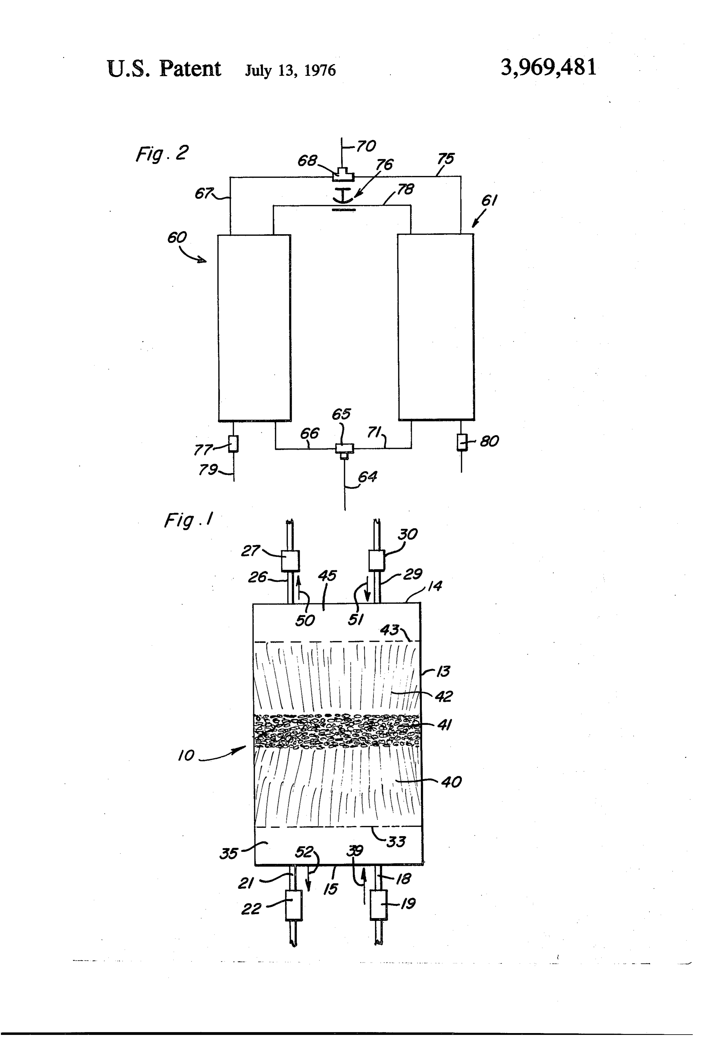
FIG. 1 is a sectional view of the purification column inventive column, as well as catalyst layers made en of the present invention, and tirely from the catalyst.
FIG. 2 is a schematic diagram illustrating the use of Located above catalyst layer 41 is a second adsor two inventive purification columns in a system to pro bent layer 42, which is provided to remove the water vide a continuous flow of purified gas. 40 produced in the catalyst layer 41. This adsorbent layer DETALED DESCRIPTION ensures that the ultimate product gas is as water free as possible.
The inventive purification column is more fully As shown in FIG. 1, located above the upper adsor shown in FIG. 1 which shows the column generally bent layer 42 is an outlet baffle 43, which with the shown at 10. The column is composed of an outer shell 45 surrounding tank 13 and upper end cap 14 define an 13 made from any suitable material such as aluminum outlet header 45. Gas passing through upper adsorbent or stainless steel, with upper end cap 14 and lower end layer 42 passes through baffle 43 to header 45 and out cap 15. Attached to the lower end cap 15 is a gas inlet of the column through purified gas conduit 26 and conduit 18 having a gas inlet valve 19 attached thereto. valve 27 in the direction of arrow 50. Also attached to lower end cap 15 is a backflush outlet 50 After operating the inventive column for a suitable conduit 21 having an attached backflush valve 22. length of time, the adsorbent layers become "filled' Likewise, upper end cap 14 is provided with two con with adsorbed water and impurities and as a result, the duits, purified gas conduit 26 and its associated valve efficiency of the adsorbents becomes markedly re 27 and main backflush conduit 29 and its associated duced. Accordingly, it is necessary to periodically "re valve 30. 55 generate' the column by desorbing the impurities and The internals of the chamber take the following form. water so that the adsorbent efficiency is improved. This Spaced a distance above the lower end cap 15 is an is accomplished by backflushing the column with puri inlet baffle plate 33, which, with lower end cap 15 and fied, product gas. In the apparatus shown in FIG. 1, the surrounding shell 13 define an inlet header 35. 60 backflushing is accomplished by closing valves 19 and Hydrogen or oxygen gas to be purified flows past valve 27 so that the forward flow of the gas to be purified 19 through inlet line 18 in the direction of arrow 39 and through the column is stopped. Next, backflush valves into header 35, which evenly distributes the gas 30 and 22 are opened and purified product gas is through inlet baffle 33. . .. passed at a suitable flow-rate countercurrently through Located immediately above inlet baffle 33 is a layer 65 the column in the direction of arrows 51 and 52. In of adsorbent, or desiccant, 40. The adsorbent, or desic addition, in order to speed the regeneration process, cant, is provided to adsorb water and other impurities the column can be provided with conventional heating before the gas streams enter the first catalyst layer. This means (not shown) which is activated during desorp prevents contamination of the catalyst, with water or tion to speed the desorption process.
Page 5
S 6
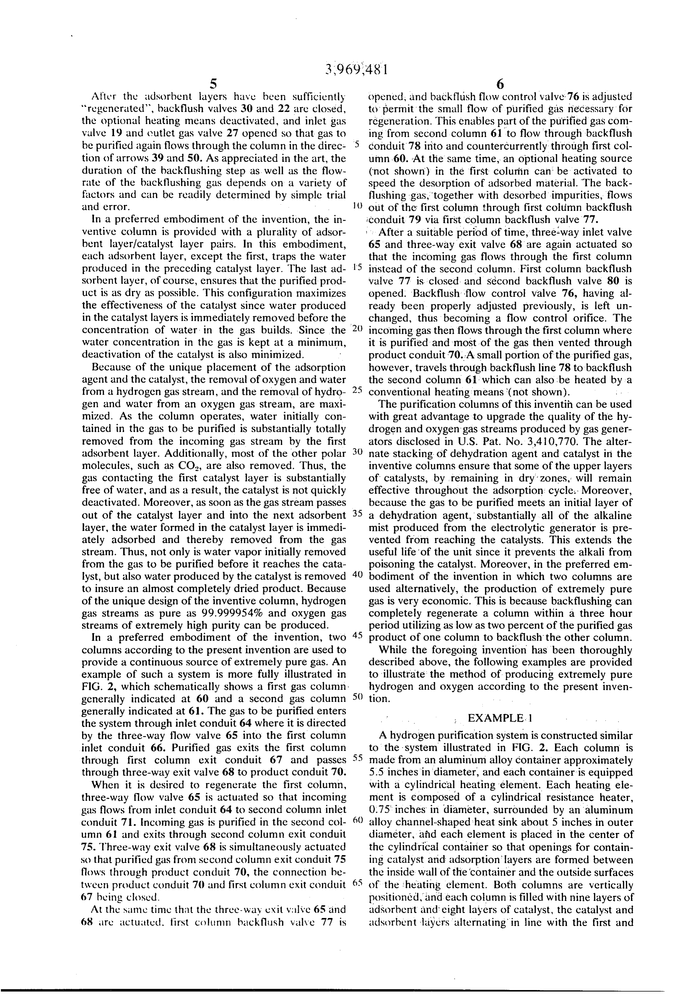
After the adsorbent layers have been sufficiently opened, and backflush flow control valve 76 is adjusted regenerated, backflush valves 30 and 22 are closed, to permit the small flow of purified gas necessary for the optional heating means deactivated, and inlet gas regeneration. This enables part of the purified gas com valve 19 and cutlet gas valve 27 opened so that gas to ing from second column 61 to flow through backflush be purified again flows through the column in the direc conduit 78 into and countercurrently through first col tion of arrows 39 and 50. As appreciated in the art, the umn 60. At the same time, an optional heating source duration of the backflushing step as well as the flow (not shown) in the first column can be activated to rate of the backflushing gas depends on a variety of speed the desorption of adsorbed material. The back factors and can be readily determined by simple trial () flushing gas, together with desorbed impurities, flows and error. out of the first column through first column backflush In a preferred embodiment of the invention, the in iconduit 79 via first column backflush valve 77. ventive column is provided with a plurality of adsor After a suitable period of time, three-way inlet valve bent layer/catalyst layer pairs. In this embodiment, 65 and three-way exit valve 68 are again actuated so each adsorbent layer, except the first, traps the water that the incoming gas flows through the first column produced in the preceding catalyst layer. The last ad 15 instead of the second column. First column backflush sorbent layer, of course, ensures that the purified prod valve 77 is closed, and second backflush valve 80 is uct is as dry as possible. This configuration maximizes opened. Backflush flow control valve 76, having al the effectiveness of the catalyst since water produced ready been properly adjusted previously, is left un in the catalyst layers is immediately removed before the changed, thus becoming a flow control orifice. The concentration of water in the gas builds. Since the 20 incoming gas then flows through the first column where water concentration in the gas is kept at a minimum, it is purified and most of the gas then vented through deactivation of the catalyst is also minimized. product conduit 70. A small portion of the purified gas, Because of the unique placement of the adsorption however, travels through backflush line 78 to backflush agent and the catalyst, the removal of oxygen and water the second column 6: which can also be heated by a from a hydrogen gas stream, and the removal of hydro conventional heating means (not shown). gen and water from an oxygen gas stream, are maxi The purification columns of this inventih can be used mized. As the column operates, water initially con with great advantage to upgrade the quality of the hy tained in the gas to be purified is substantially totally drogen and oxygen gas streams produced by gas gener removed from the incoming gas stream by the first ators disclosed in U.S. Pat. No. 3,410,770. The alter adsorbent layer. Additionally, most of the other polar 30 nate stacking of dehydration agent and catalyst in the molecules, such as CO, are also removed. Thus, the inventive columns ensure that some of the upper layers gas contacting the first catalyst layer is substantially of catalysts, by remaining in dry zones, will remain free of water, and as a result, the catalyst is not quickly effective throughout the adsorption cycle. Moreover, deactivated. Moreover, as soon as the gas stream passes because the gas to be purified meets an initial layer of out of the catalyst layer and into the next adsorbent 35 a dehydration agent, substantially all of the alkaline layer, the water formed in the catalyst layer is immedi mist produced from the electrolytic generator is pre ately adsorbed and thereby removed from the gas vented from reaching the catalysts. This extends the stream. Thus, not only is water vapor initially removed useful life of the unit since it prevents the alkali from from the gas to be purified before it reaches the cata poisoning the catalyst. Moreover, in the preferred em lyst, but also water produced by the catalyst is removed 40 bodiment of the invention in which two columns are to insure an almost completely dried product. Because used alternatively, the production of extremely pure of the unique design of the inventive column, hydrogen gas is very economic. This is because backflushing can gas streams as pure as 99.999954% and oxygen gas completely regenerate a column within a three hour streams of extremely high purity can be produced. period utilizing as low as two percent of the purified gas In a preferred embodiment of the invention, two 45 product of one column to backflush the other column. columns according to the present invention are used to While the foregoing invention has been thoroughly provide a continuous source of extremely pure gas. An described above, the following examples are provided example of such a system is more fully illustrated in to illustrate the method of producing extremely pure FIG. 2, which schematically shows a first gas column hydrogen and oxygen according to the present inven generally indicated at 60 and a second gas column 50 to.
generally indicated at 61. The gas to be purified enters EXAMPLE.1 the system through inlet conduit 64 where it is directed by the three-way flow valve 65 into the first column A hydrogen purification system is constructed similar inlet conduit 66. Purified gas exits the first column to the system illustrated in FIG. 2. Each column is through first column exit conduit 67 and passes made from an aluminum alloy container approximately through three-way exit valve 68 to product conduit 70. 5.5 inches in diameter, and each container is equipped When it is desired to regenerate the first column, with a cylindrical heating element. Each heating ele three-way flow valve 65 is actuated so that incoming ment is composed of a cylindrical resistance heater, gas flows from inlet conduit 64 to second column inlet 0.75 inches in diameter, surrounded by an aluminum conduit 71. Incoming gas is purified in the second col 60 alloy channel-shaped heat sink about 5 inches in outer umn 61 and exits through second column exit conduit diameter, and each element is placed in the center of 75. Three-way exit valve 68 is simultaneously actuated the cylindrical container so that openings for contain so that purified gas from second column exit conduit 75 ing catalyst and adsorption layers are formed between flows through product conduit 70, the connection be the inside wall of the container and the outside surfaces tween product conduit 70 and first column exit conduit 65 of the heating element. Both columns are vertically 67 bucing closed. positioned, and each column is filled with nine layers of At the same time that the three-way crit valve 65 and adsorbent and eight layers of catalyst, the catalyst and 68 are actuated, first collinn backflush valve 77 is adsorbent layers alternating in line with the first and
Page 6
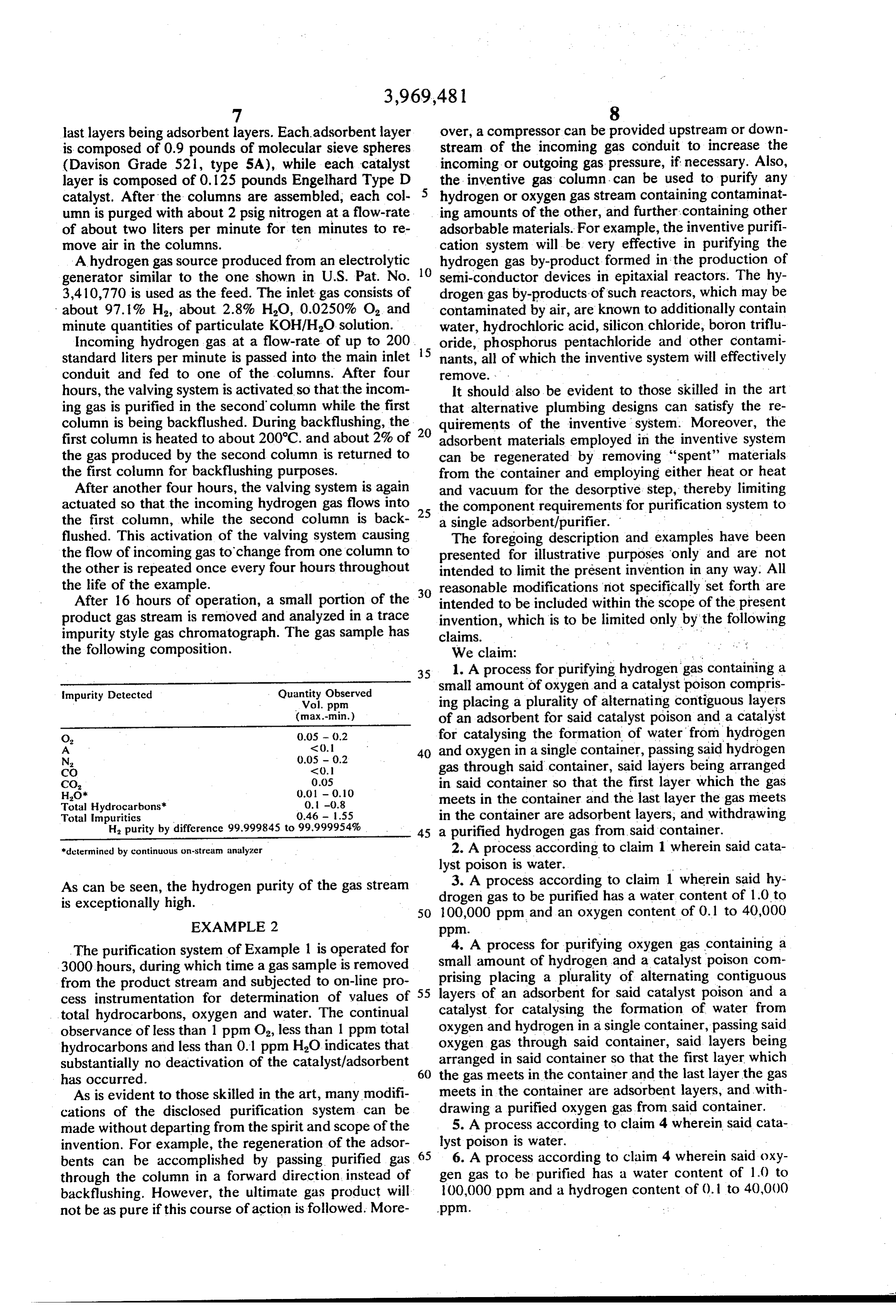
last layers being adsorbent layers. Each adsorbent layer over, a compressor can be provided upstream or down is composed of 0.9 pounds of molecular sieve spheres stream of the incoming gas conduit to increase the (Davison Grade 521, type 5A), while each catalyst incoming or outgoing gas pressure, if necessary. Also, layer is composed of 0.125 pounds Engelhard Type D the inventive gas column can be used to purify any catalyst. After the columns are assembled, each col hydrogen or oxygen gas stream containing contaminat umn is purged with about 2 psig nitrogen at a flow-rate ing amounts of the other, and further containing other of about two liters per minute for ten minutes to re adsorbable materials. For example, the inventive purifi move air in the columns. ;: cation system will be very effective in purifying the A hydrogen gas source produced from an electrolytic 10 hydrogen gas by-product formed in the production of generator similar to the one shown in U.S. Pat. No. semi-conductor devices in epitaxial reactors. The hy 3,410,770 is used as the feed. The inlet gas consists of drogen gas by-products of such reactors, which may be about 97.1% H, about 2.8% HO, 0.0250% O, and contaminated by air, are known to additionally contain minute quantities of particulate KOH/HO solution. water, hydrochloric acid, silicon chloride, boron triflu Incoming hydrogen gas at a flow-rate of up to 200 15 oride, phosphorus pentachloride and other contami standard liters per minute is passed into the main inlet nants, all of which the inventive system will effectively conduit and fed to one of the columns. After four reOWe. . .
hours, the valving system is activated so that the incom It should also be evident to those skilled in the art ing gas is purified in the second column while the first that alternative plumbing designs can satisfy the re column is being backflushed. During backflushing, the quirements of the inventive system. Moreover, the first column is heated to about 200°C. and about 2% of 20 adsorbent materials employed in the inventive system the gas produced by the second column is returned to can be regenerated by removing "spent' materials the first column for backflushing purposes. from the container and employing either heat or heat After another four hours, the valving system is again and vacuum for the desorptive step, thereby limiting actuated so that the incoming hydrogen gas flows into 25 the component requirements for purification system to the first column, while the second column is back a single adsorbent/purifier.
flushed. This activation of the valving system causing The foregoing description and examples have been the flow of incoming gas to change from one column to presented for illustrative purposes only and are not the other is repeated once every four hours throughout intended to limit the present invention in any way. All the life of the example. reasonable modifications not specifically set forth are After 16 hours of operation, a small portion of the 30 intended to be included within the scope of the present product gas stream is removed and analyzed in a trace invention, which is to be limited only by the following impurity style gas chromatograph. The gas sample has claims. . .. . .. the following composition. We claim: ' ' 35 1. A process for purifying hydrogen gas containing a impurity Detected Quantity Observed small amount of oxygen and a catalyst poison compris Vol. ppm ing placing a plurality of alternating contiguous layers (max.-min.) of an adsorbent for said catalyst poison and a catalyst
O 0.05 - 0.2 for catalysing the formation of water from hydrogen
0.05 - 0.2 40 and oxygen in a single container, passing said hydrogen
CO <0. gas through said container, said layers being arranged
in said container so that the first layer which the gas
Total Hydrocarbons' 0.1 -0.8 meets in the container and the last layer the gas meets Total Impurities 0.46 - 1.55 in the container are adsorbent layers, and withdrawing H, purity by difference 99.999845 to 99.999954% 45 a purified hydrogen gas from said container. "determined by continuous on-stream analyzer 2. A process according to claim 1 wherein said cata lyst poison is water.
3. A process according to claim 1 wherein said hy
As can be seen, the hydrogen purity of the gas stream drogen is exceptionally high. gas to be purified has a water content of 1.0 to
The purification system of Example 1 is operated for 4. A process for purifying oxygen gas containing a 3000 hours, during which time a gas sample is removed small amount of hydrogen and a catalyst poison com from the product stream and subjected to on-line pro 55 prising placing a plurality of alternating contiguous cess instrumentation for determination of values of layers of an adsorbent for said catalyst poison and a total hydrocarbons, oxygen and water. The continual catalyst for catalysing the formation of water from oxygen and hydrogen in a single container, passing said observance of less than 1 ppm O, less than 1 ppm total oxygen hydrocarbons and less than 0.1 ppm HO indicates that gas through said container, said layers being substantially no deactivation of the catalyst/adsorbent arranged in said container so that the first layer which has occurred. 60 the gas meets in the container and the last layer the gas As is evident to those skilled in the art, many modifi meets in the container are adsorbent layers, and with cations of the disclosed purification system can be drawing a purified oxygen gas from said container. made without departing from the spirit and scope of the 5. A process according to claim 4 wherein said cata invention. For example, the regeneration of the adsor 65 lyst poison is water.
bents can be accomplished by passing purified gas 6. A process according to claim 4 wherein said oxy through the column in a forward direction instead of gen gas to be purified has a water content of 1.0 to backflushing. However, the ultimate gas product will 100,000 ppm and a hydrogen content of 0.1 to 40,000 not be as pure if this course of action is followed. More ppm.
Page 7
7. A process for continuously purifying an incoming incoming gas from the first purification zone to the hydrogen gas stream containing small amounts of oxy second purification zone, (6) withdrawing a portion of gen and a catalyst poison comprising (1) establishing a the purified product from said second purification first purification zone in a first column and a second zone, (7) causing a portion of the purified product purification zone in a second column, each zone com from said second purification zone to flow through the prising a plurality of alternating contiguous layers of an first purification zone and (8) transferring the incom adsorbent for said catalyst poison and a catalyst for ing gas stream back to the first purification zone and catalyzing the formation of water from hydrogen and repeating steps 3-7.
oxygen, said adsorbent and catalyst layers being ar 11. A process according to claim 10 wherein said ranged in each column so that the first and last layers catalyst poison is water.
met by gas flowing through each column are adsorbent 12. A process according to claim 10 wherein the first layers, (2) causing said incoming gas stream to flow purification zone is backflushed with a portion of the into the first purification zone, (3) withdrawing a por product produced in the second purification zone and tion of the purified product from the first purification further wherein the second purification zone is back Zone, (4) causing a portion of the purified product 15 flushed with a portion of the purified product produced from said first purification zone to flow through the in the first purification zone.
second purification zone, (5) transferring the flow of 13. A process according to claim 1 wherein said incoming gas from the first purification zone to the hydrogen gas contains a small amount of polar impuri second purification zone, (6) withdrawing a portion of ties and said absorbent is an absorbent for said polar the purified product from said second purification 20 impurities.
Zone, (7) causing a portion of the purified product 14. The process according to claim 1 wherein said from said second purification zone to flow through the hydrogen gas is produced in an electrolytic generator first purification zone and (8) transferring the incom and contains alkaline impurities and said absorbent is ing gas stream back to the first purification zone and 25 an absorbent for said alkaline impurities. repeating steps 3-7. 15. The process according to claim 4 wherein said 8. A process according to claim 7 wherein said cata oxygen gas contains polar impurities and said absor lyst poison is water. bent is an absorbent for said polar impurities. 9. A process according to claim 7 wherein the first 16. The process according to claim 4 wherein said purification zone is backflushed with a portion of the 30 oxygen gas is produced in an electrolytic generator and product produced in the second purification zone and contains alkaline impurities and said absorbent is an further wherein the second purification zone is back absorbent for said alkaline impurities. flushed with a portion of the purified product produced 17. The process according to claim 7 wherein said in the first purification zone. incoming hydrogen gas stream contains polar impuri 10. A process for continuously purifying an incoming 35 ties and said absorbent is an absorbent for said polar oxygen gas stream containing small amounts of hydro impurities.
gen and a catalyst poison comprising (l) establishing a 18. The process according to claim 7 in which said first purification zone in a first column and a second incoming hydrogen gas stream is produced in an elec purification zone in a second column, each Zone com trolytic generator and contains alkaline impurities and prising a plurality of alternating contiguous layers of an 40 said absorbent is an absorbent for said alkaline impuri absorbent for said catalyst poison and a catalyst for ties.
catalyzing the formation of water from oxygen and 19. The process according to claim 10 in which said hydrogen, said absorbent and catalyst layers being ar incoming oxygen gas stream contains polar impurities ranged in each column so that the first and last layers and said absorbent is an absorbent for said polar impu met by gas flowing through each column are layers of 45 rities.
adsorbent, (2) causing said incoming gas stream to flow . 20. The process according to claim 10 in which said into the first purification zone; (3) withdrawing a por incoming oxygen gas stream is produced in an electro tion of the purified product from the first purification lytic generator and contains alkaline impurities and zone, (4) causing a portion of the purified product . said absorbent is an absorbent for said alkaline impuri from said first purification zone to flow through the ties. ck ck k ck sk second purification zone, (5) transferring the flow of
Provenance
- Collection
- Cited prior art
- Original PDF
- patentimages.storage.googleapis.com →
- Filed
- 1972-11-03
- Pages
- 7
- Method
- pdftotext (the PDF's own text layer) + pdftoppm 300dpi page scans
- Source
- Google Patents bibliographic record
- Granted
- 1976-07-13
- Inventors
- John N. Murray; Robert J. Hynek; Isotopes Inc
- Transcribed from
- patentimages.storage.googleapis.com →