patent · US5488828
Energy generating apparatus
6 February 1996
Page 1 — bibliographic record
III
III
United States Patent (19) 11) Patent Number: 5,488,828 Brossard (45) Date of Patent: Feb. 6, 1996
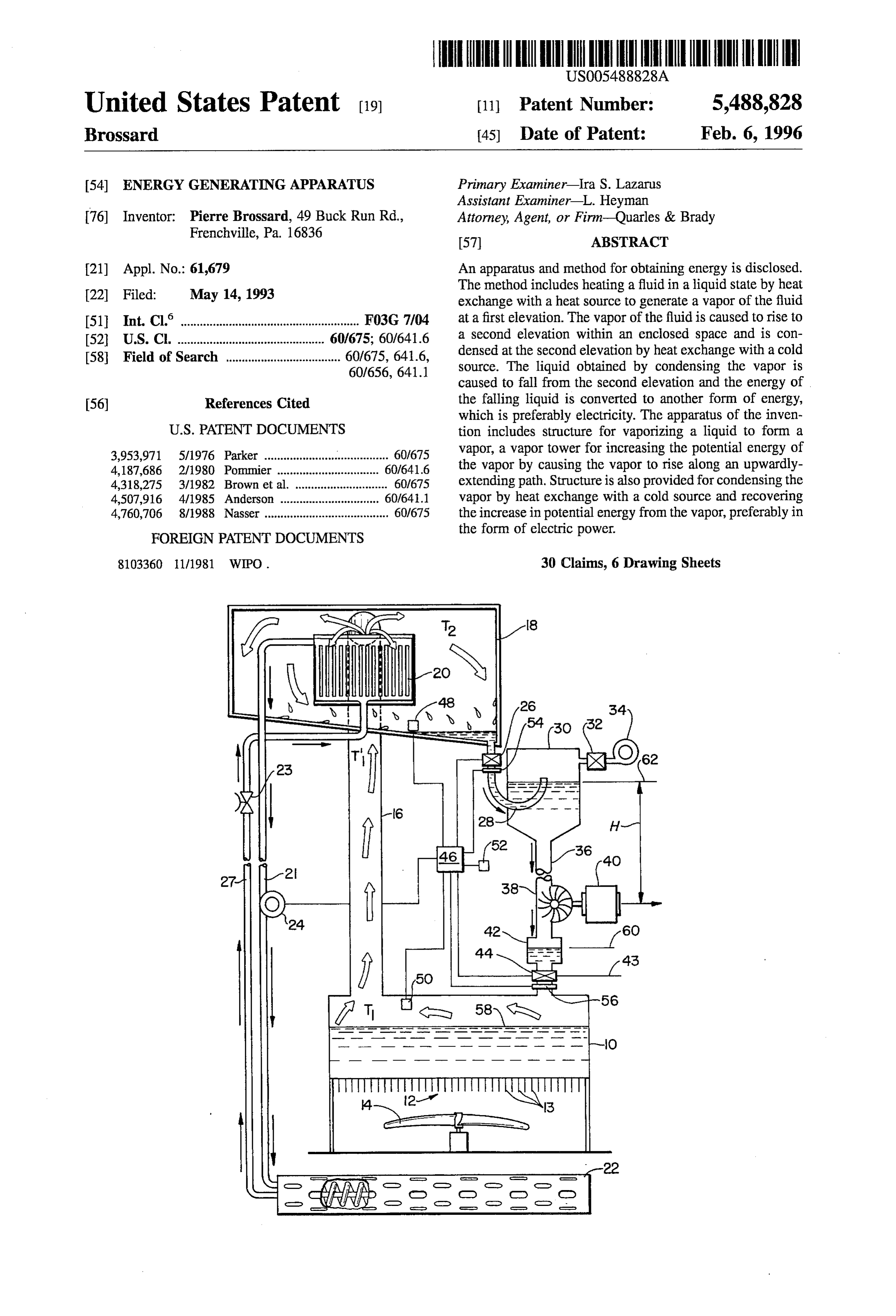
(54) ENERGY GENERATING APPARATUS Primary Examiner-Ira S. Lazarus Assistant Examiner-L. Heyman 76 Inventor: Pierre Brossard, 49 Buck Run Rd., Attorney, Agent, or Firm-Quarles & Brady Frenchvill renchville, Pa. 16836 57) ABSTRACT 21) Appl. No.: 61,679 An apparatus and method for obtaining energy is disclosed. The method includes heating a fluid in a liquid state by heat 22 Filed: May 14, 1993 exchange with a heat source to generate a vapor of the fluid (51 Int. Cl. ............................ F03G 7/04 at a first elevation. The vapor of the fluid is caused to rise to 52 U.S. C. .............................................. 60/675; 60/641.6 a second elevation within an enclosed space and is con 58 Field of Search .................................... 60/675, 6416, densed at the second elevation by heat exchange with a cold 60/656, 641.1 source. The liquid obtained by condensing the vapor is caused to fall from the second elevation and the energy of 56) References Cited the falling liquid is converted to another form of energy, which is preferably electricity. The apparatus of the inven
vapor, a vapor tower for increasing the potential energy of the vapor by causing the vapor to rise along an upwardly
4,318,275 3/1982 Brown et al. .. - - - - - 60/675 extending path. Structure is also provided for condensing the 4,507,916 4/1985 Anderson ... 60/641.1 vapor by heat exchange with a cold source and recovering 4,760,706 8/1988 Nasser ........ 60/675 the increase in potential energy from the vapor, preferably in FOREIGN PATENT DOCUMENTS the form of electric power.
8103360 1 1/1981 WIPO. 30 Claims, 6 Drawing Sheets
Page 2
Drawing sheet — no readable text.
Page 3
Drawing sheet — no readable text.
Page 4
Drawing sheet — no readable text.
Page 5
Drawing sheet — no readable text.
Page 6
Drawing sheet — no readable text.
Page 7
Drawing sheet — no readable text.
Page 8
ENERGY GENERATING APPARATUS BRIEF DESCRIPTION OF THE DRAWINGS
BACKGROUND OF THE INVENTION The attached drawings depict presently preferred embodi ments of the invention. The drawings, however, should not
The purpose of this invention is to take advantage of 5 be viewed as limiting the invention to the precise arrange physical properties of vaporization and condensation to ments and instrumentalities shown, wherein: provide a useable source of energy. A naturally-occurring or FIG. 1 is a thermodynamic diagram showing the theory of man-made temperature differential is used as an energy operation of a first embodiment of the invention, wherein the source to operate the device. surrounding air is warmer than the sea or subterranean water 10 Supply.
SUMMARY OF THE INVENTION FIG. 2 is athermodynamic diagram showing the theory of According to the present invention, a boiler having a operation of a second embodiment of the invention, wherein heating source is provided for heating a volume of liquid the air surrounding the device is colder than the sea or contained in the boiler, thereby generating vapor. The vapor Subterranean water supply.
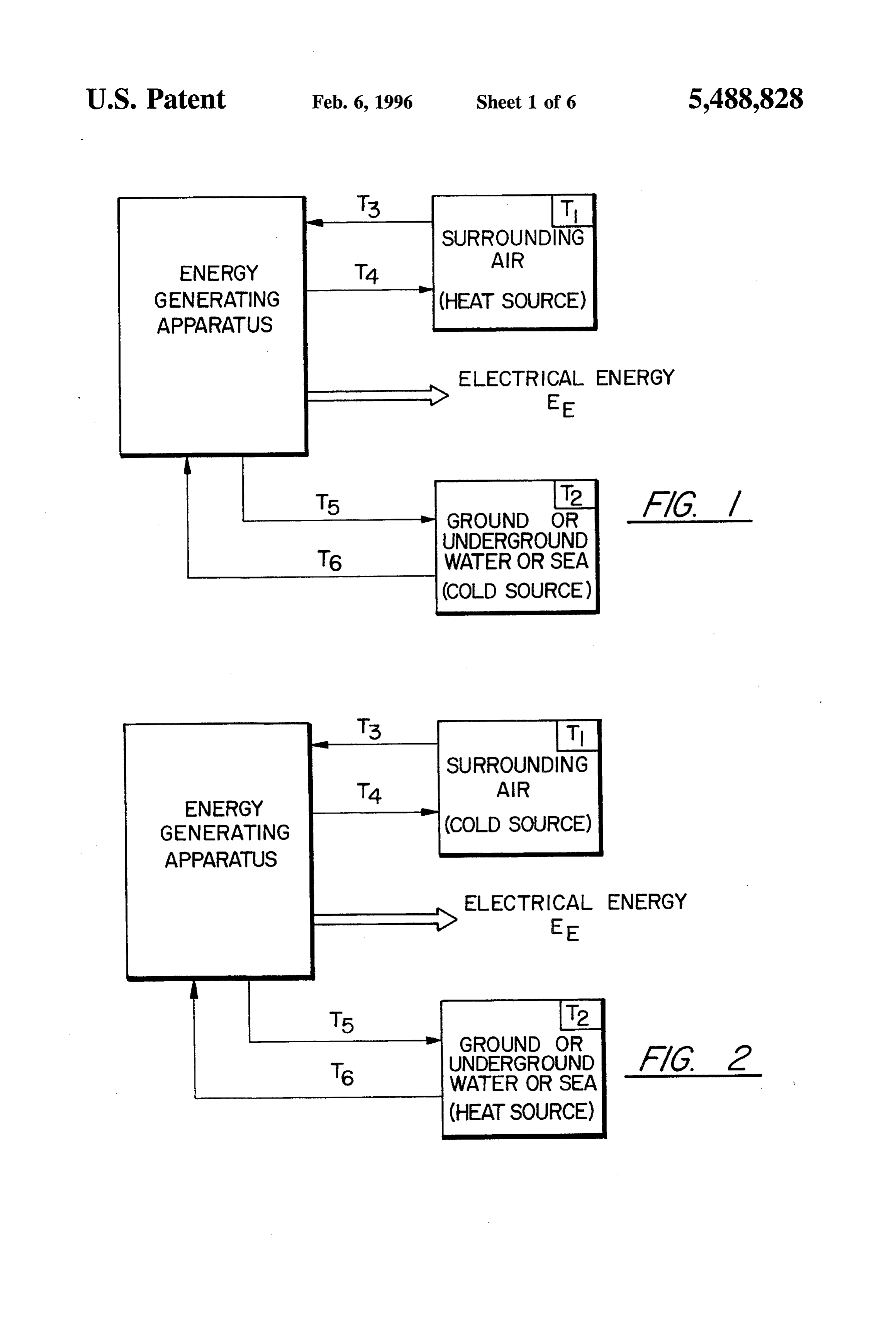
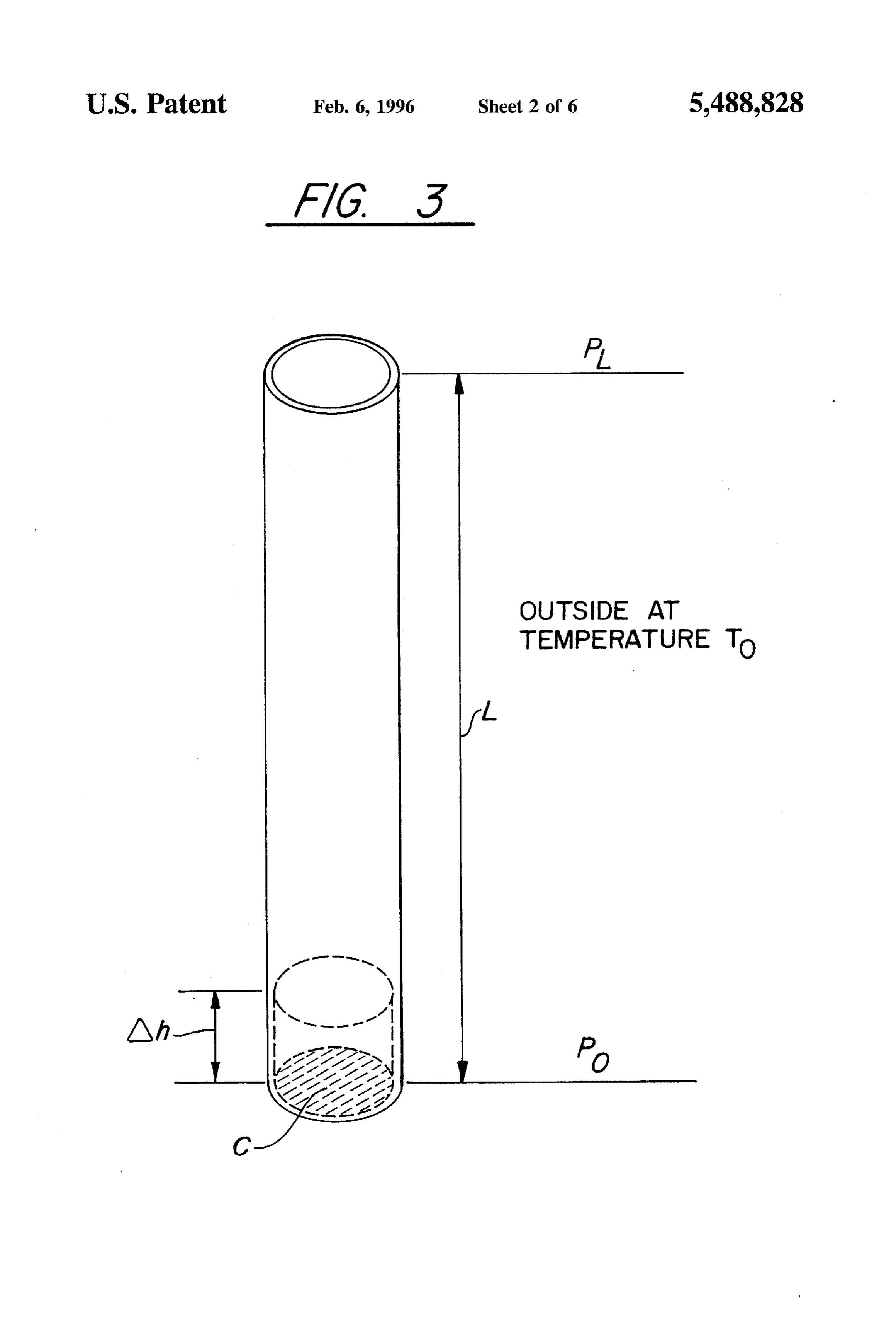
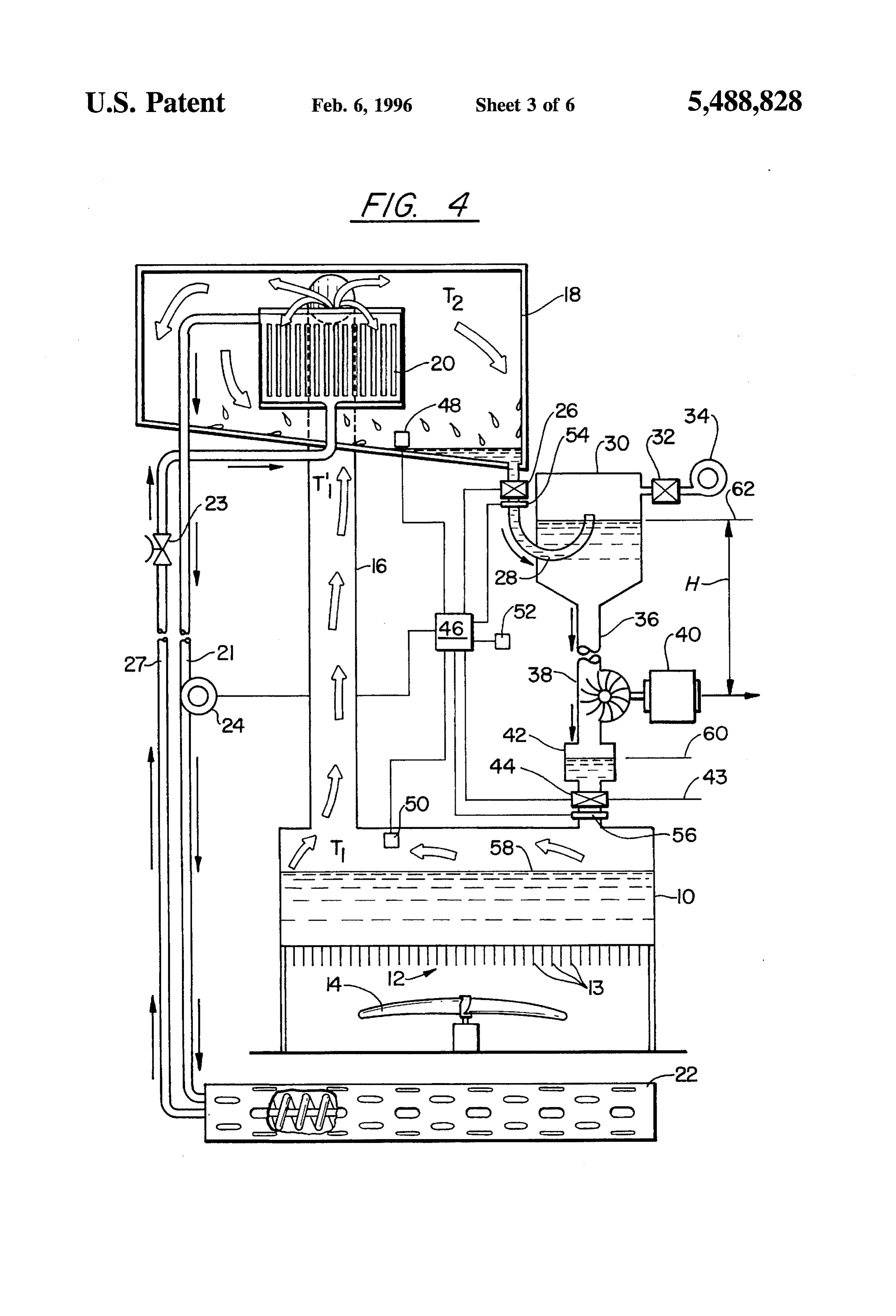
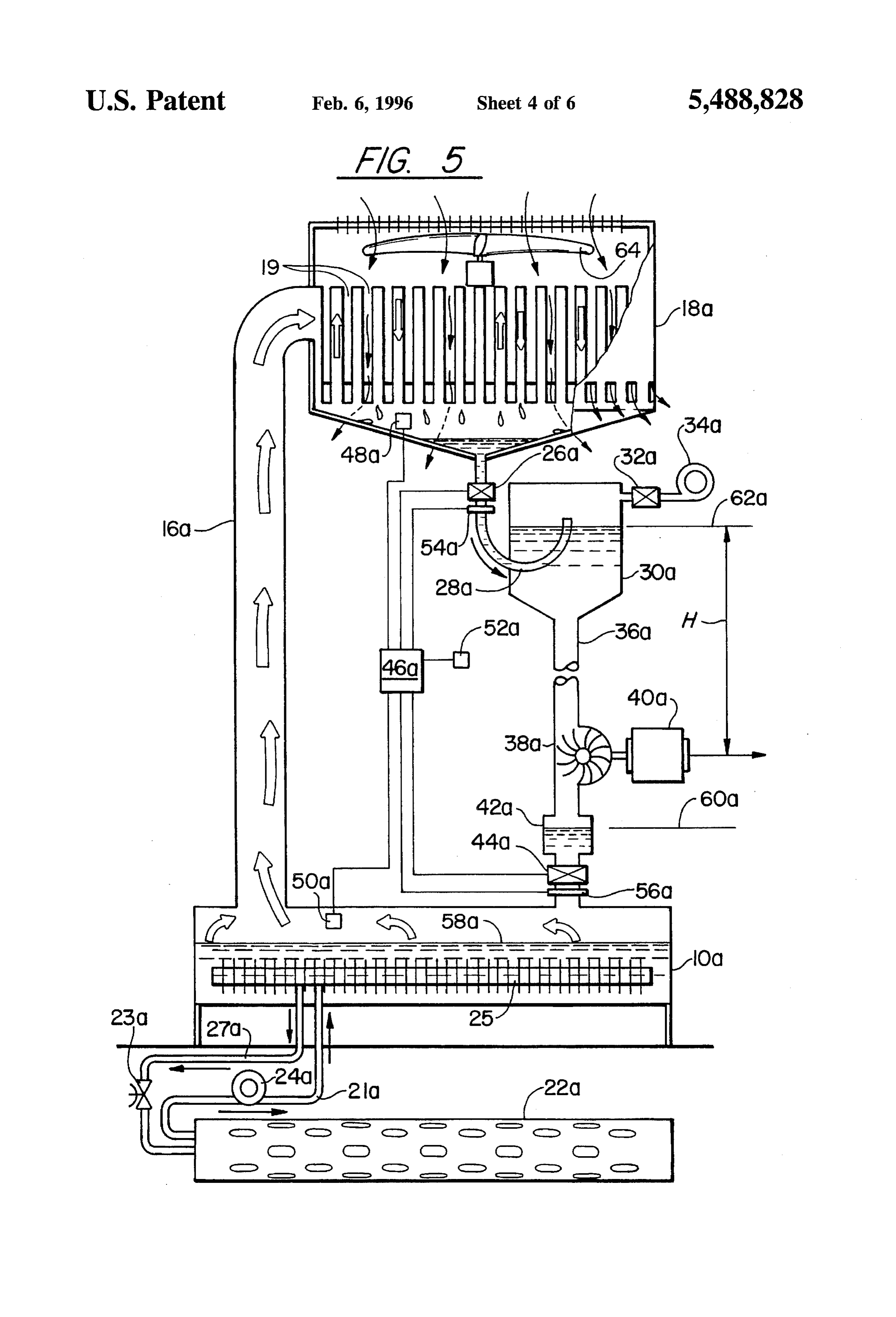
is caused to pass out of the boiler and into an upwardly 15 FIG. 3 is a diagram showing the theory of operation of the extending gas-tight vapor tower, connected at its upper end invention for generating useable energy. to a condenser. As the vapor is forced upward, its potential FIG. 4 shows a schematic diagram of a first embodiment energy increases. When the vapor reaches the condenser, it of the present invention which is designed for conditions is condensed into liquid by means of a cold source, and is 20 wherein the sea or subterranean water supply is colder than collected in a primary reservoir mounted at the top of a the air surrounding the device. liquid tower. At the base of the liquid tower is a turbine FIG. 5 shows a schematic diagram of a second embodi driving a generator for generating electricity. The condensed ment of the present invention which is designed for condi liquid passes downwardly through the liquid tower, through tions wherein the sea or subterranean water supply is the turbine, and is collected in a collector reservoir. The movement of the liquid through the turbine causes the 25 warmer FIG. 6 than the air surrounding the device.
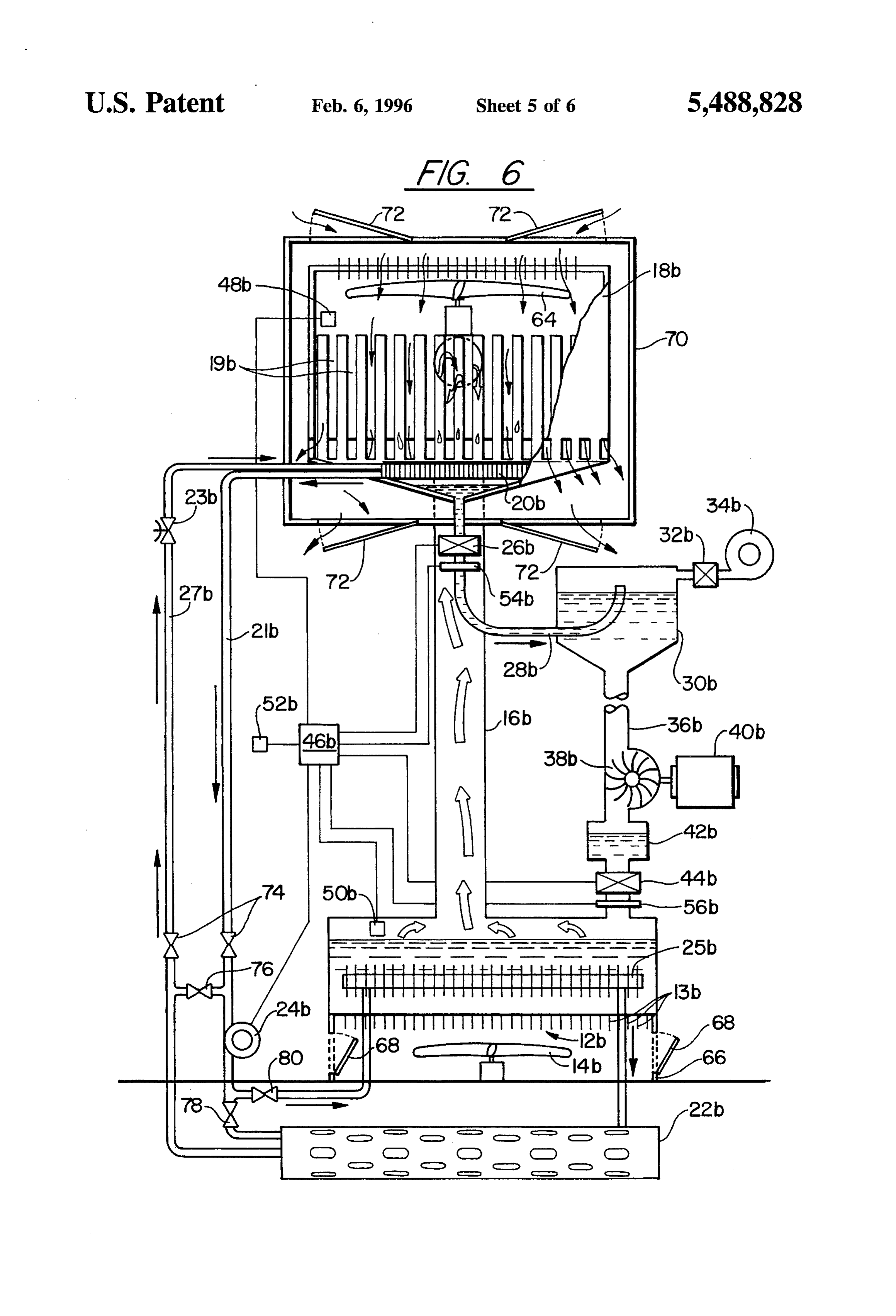
shows a schematic diagram of a third embodiment generator to spin, and thereby provides a source of electric of the present invention which is designed for conditions ity.
Servo-valves connected between the condenser and the wherein the temperature of the air may fluctuate above and reservoir, and the collector tank and the boiler, help regulate below the temperature of the sea or subterranean water Supply.
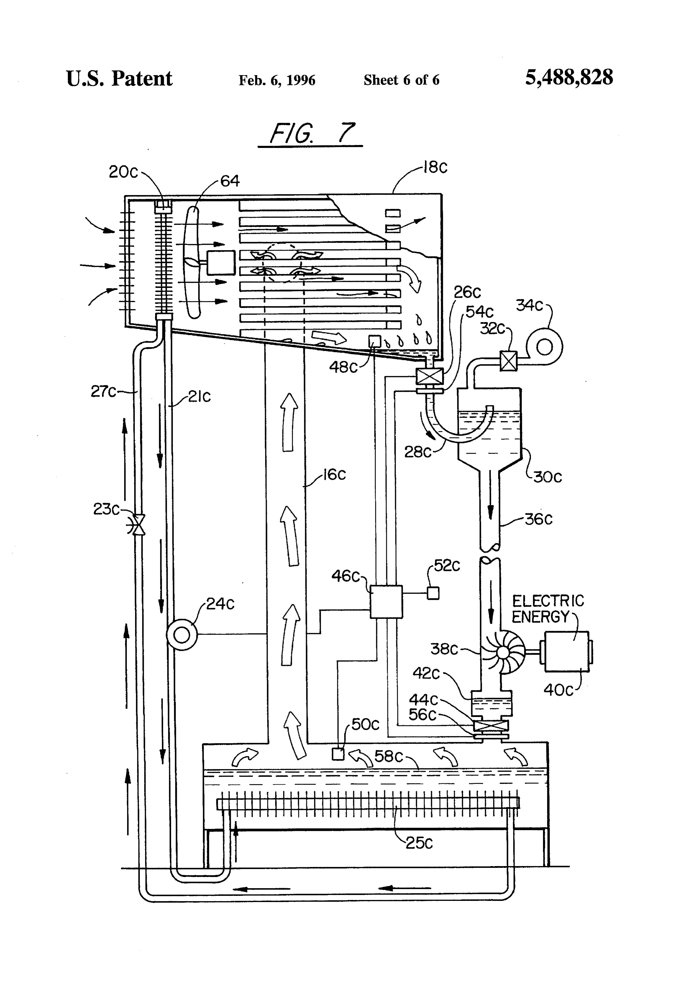
the flow of liquid in the device. Regulating the flow of liquid 30 maintains proper pressure differentials, which enable the FIG. 7 is a schematic diagram of a fourth embodiment of device to continue to operate. In addition, a vacuum pump the device according to the present invention capable of connected to the primary reservoir through a third servo operating in conditions where a naturally occurring tem valve controls the pressure in the primary reservoir to help perature differential is not available. regulate liquid flow into said primary reservoir during 35 DETAILED DESCRIPTION OF THE initiation of the device.
INVENTION
Electricity generated by the generator is used to operate one or more electric fans and a compressor for transferring A thermodynamic diagram representing the operation of energy from a heat source to the boiler, and for transferring 40 the device of the present invention is shown in FIGS. 1 and heat out of the condenser to a cold source. The generator is 2. In FIGS. 1 and 2, T is the temperature of the air also used to power the vacuum pump, the servo-valves and surrounding the device, T is the temperature of the sea or a regulator system. subterranean water supply, T is the temperature of the air The heat source and the cold source for supplying energy drawn into the device, T is the temperature of the air after to the device can be the atmosphere surrounding the device, 45 it has been passed through the device, T is the temperature a subterranean well or the sea. These external heat/cold of the subterranean water or sea water after it has been used sources are utilized to generate vapor in the boiler, force the by the device and T is the temperature of subterranean vapor to rise from the boiler to the condenser at the top of water or sea water when it enters the device. the vapor tower, and to condense the vapor into liquid form. FIG. 1 represents the operation of a first embodiment of If the vapor tower and liquid tower are properly dimen 50 the device for conditions where the air surrounding the sioned, the increase in potential energy imparted to the vapor apparatus (T,) is warmer than the sea or subterranean water as it rises up through the vapor tower will be sufficient to supply (T). In FIG. 1, T is greater than T. because heat sustain the operation of the device, and simultaneously energy is removed from the surrounding air as it passes provide a source of electric power which can be used for through the device. In contrast, the temperature T of other purposes. 55 subterranean water or sea water entering the device is In its simplest form, the device may be thought of as a increased by absorbing heat as it passes through the device. hydroelectric power plant in which an energy source other Thus, T is greater than T. In FIG. 1, the temperature than the electricity generated by the power plant is used to differential between T (the air surrounding the device) and pump water from a lower portion of the device to an upper T (the subterranean water supply or sea) is used as a source portion of the device. A portion of the electricity generated 60 for electric energy E.
by the power plant is used internally in the device to FIG. 2 is similar to FIG. 1, except that in FIG. 2, the air facilitate the exploitation of an external power source, i.e. surrounding the apparatus is colder than the subterranean the temperature differential between the hot and cold source. water supply or sea water. In FIG. 2, T is less than T, and The total electric power required to exploit the external T is less than T. The water serves as a heat source and the power source is less than the total amount of electricity 65 atmosphere as a cold source. Thus, FIG. 2 also shows that generated by the power plant. Thus, the device is capable of the device of the present invention uses a temperature providing a useable source of energy. differential between the atmospheric air surrounding the
Page 9
device and ground water or sea water in order to generate Et-Eot-LCg(pop) (7) electricity. FIGS. 1 and 2 demonstrate that, depending upon the environmental conditions, the atmosphere surrounding the device or a subterranean water supply (or the sea) can In equation (7), since po is greater than pi, then LCg(po each serve as a hot or cold source.
p) will be positive. Based upon equation (8), it can be seen
For the purpose of understanding the present invention, it that adding a quantity of energy Q to the mass of air at the is helpful to first consider a simplified example which bottom of the pipe results in an increase in the total energy demonstrates the theory of operation of the device. FIG. 3 is of the air when it arrives at the top of the pipe which is: provided for this purpose.
In FIG. 3, a pipe of length L and of cross-section C is 10 positioned vertically. Initially, the temperature of the air inside and outside of the pipe (cold source) is To and has a It should be noted that after exiting the pipe, the warm air mass per unit volume of po M is the mass of a volume of at temperature T will distribute its heat Q to the cold air air Vo inside of the pipe defined by cross-section C and ated outside the pipe. As a result, the increase in energy associ length Ah. For the purpose of this example, it will be 15 heat with the air will be LCg(pop). Thus, the transfer of assumed that the air in the pipe is adiabatic, i.e. there is no energy from the hot source to the cold source through transfer of heat from the air inside the pipe to the air outside the pipe results in an increase in potential energy for the air the pipe. passing through the pipe, said increase being L'Cg(pop). In the above equation, it should be noted that pop is a
In FIG. 3, the temperature of the mass of air M can be constant defined by the difference of temperature between increased from T to T by adding a quantity of heat Q (heat 20 the cold source and the hot source. Likewise, g is also a source). Q can be mathematically represented as constant. Thus, under the conditions specified, by adjusting CM or CVopo L and C (the dimensions of the pipe), the increase of total energy of the air as it rises from the bottom of the pipe to the where C is the specific heat of the air. The total energy of 25 top of the pipe can be adjusted to any value per unit of mass. this mass of air N when it is at the bottom of the pipe, before Since pop is a positive number, it can also be seen that heating, is then L°Cg(pop), is a positive number. Thus the increase in potential energy is positive.
Eo-Epo-Eo (1) In the foregoing example, in order to simplify the math ematics, it was assumed that p, the mass per unit volume, wherein E is the potential energy at altitude zero and Eo 30 was a constant with altitude. This assumption is reasonable is the total kinetic energy at altitude Zero before heating. because, as discussed below, the height of the device is After heating, the total energy of this same mass of air may unlikely to exceed 300 meters. However, even if the varia be described as tion of p with altitude were taken into account, the more precise mathematical calculation would show that the
Eo-Eot-O. (2) 35 increase in total energy is a function only of the dimension After heating, Ah increases to accommodate the increase of the pipe.
in the volume of the air. Thus the mass of air M will have In the example, certain significant assumptions were a mass-per-unit volume less than the air above and below it. made to simplify the mathematical calculations. These include:
Consequently, this air will rise in the pipe. During this 40 displacement, the total energy E at altitude h of this mass 1. that a hot and cold source are available, of air will now become: 2. that the displacement of air in the pipe is adiabatic, i.e. there is no transfer of heat from the air inside the pipe
El-Eot) w (3) to the air outside the pipe; and where X is the sum of the external forces acting on the 45 3. that there is no external work done by the air in the pipe.
mass of air. By performing a complete mathematical inte The various embodiments of the present invention, which gration of Ah over the length of the pipe L, it can be shown will be described in detail below, are based upon the that principal demonstrated above with respect to FIG. 3, and achieves the above three (3) conditions. In FIG. 3, it was demonstrated that the potential energy of a volume of gas in
a pipe could be increased by applying a quantity of heat and where P is the atmospheric pressure at altitude zero, P, is then allowing the gas to rise in the pipe. The present the atmospheric pressure at altitude h, and g is the accel invention is designed such that the increase in potential eration of gravity. For a vertical displacement of length L, energy, acquired by a gas as it rises in a tower, is transformed and considering all the air in the pipe at T, the summation 55 into a usable energy source which may be tapped for other of external forces is uses. This result is achieved by transforming the gas to a liquid state for converting its increased potential energy to a (5) different form of energy.
A first embodiment of the device according the present since Po P-pogL, and Mg=p CLg then it can be shown that 60 invention is shown in FIG. 4. The device includes a boiler 10 and a heat exchanger 12. Heat exchanger 12 transfers
Xwr-LCg(pop.) (6) heat from the surrounding atmosphere into boiler 10 for boiling a liquid contained therein and thereby creating where p is the mass per unit volume of the air after heating. vapor, Associated with the heat exchanger 12 is a fan 14 for From the foregoing, and by combining equations 3 and 6, it 65 the purpose of improving the transfer of heat from the air can be seen that the total energy of the mass of air at altitude surrounding the device to the heat exchanger 12. The air, L will be under these circumstances, functions as a heat source.
Page 10
In FIG. 4, heat exchanger 12 is shown as a series of heat from exiting condenser 18. Near the top of primary reservoir conductive fins 13 attached to the bottom of boiler 10. The 30 is an opening controlled by servo-valve 32. When servo heat conductive fins provide additional surface area for heat valve 32 is opened, it forms a gas-tight passage between an transfer from the air surrounding the device into boiler 10. upper portion of primary reservoir 30 and vacuum pump 34. If this type of heat exchanger is used, fan 14 is arranged to Servo-valve 32 can be opened or closed, as necessary, to force air over the surface of the heat conducting fins 13 to vary the pressure in primary reservoir 30. However, as further facilitate the transfer of heat from the air to the boiler. explained below, its primary purpose is to assist in initiating FIG. 4 shows one possible arrangement for transferring heat the operation of the invention. from the outside air to the boiler 10. However, it should be At a lower portion of primary reservoir 30 is an opening noted that numerous alternative embodiments are also pos 10 where the primary reservoir is attached to liquid tower 36. sible to achieve this same result. For example, instead of a The opening allows liquid from primary reservoir 30 to pass single large fan 14 blowing air directly upon the bottom of into the liquid tower 36.
boiler 10, a series of fans can be positioned to blow air down At a lower portion of liquid tower 36, means are provided the length of fins 13 across the bottom of the boiler 10. for generating electricity from the potential energy stored in Alternatively, heat exchanger 12 may comprise a series of 15 the column of liquid in liquid tower 36 and primary reservoir heat conductive pipes passing through the interior of boiler 30. The means for generating electricity can be a turbine, 10 and carrying air forced through them by a fan. In general, paddlewheel or any other suitable device operatively any suitable mechanism for transferring heat from the out coupled with an electric generator. In the embodiment side air into boiler 10 will be sufficient for the device to shown in FIG.4, a turbine 38 and generator 40 are used for function. 20 the purpose of generating electricity from the column of Attached to the upper portion of the boiler is an upwardly liquid. Liquid exiting turbine 38 is collected in collector extending gas-tight vapor tower 16. Vapor tower 16 has, at reservoir 42. Collector reservoir 42 is provided with a its upper end, a condenser 18. Evaporator 20 is located servo-valve 44 for controlling the flow of water between within condenser 18 and functions as a cooling mechanism collector reservoir 42 and boiler 10. for condensing liquid in condenser 18. 25 Servo-valves 26 and 44 are preferably proportional Evaporator 20 and heat exchanger 22 operate in coopera valves. Once the device reaches steady state conditions, the tion with compressor 24, ducts 21, 27 and expansion valve position of these valves will remain essentially fixed. Nev 23 to function as a heat pump. Heat associated with the ertheless, the proportional valves are preferred for the pur vapor generated in boiler 10, is collected in condenser 18 pose of precisely regulating the operation of the device when and absorbed by evaporator 20. The heat is then transferred 30 it is initiated and under steady state conditions. to the underground cold water source, or to the sea, by means As shown in FIG. 4, a regulator 46, which may be a of compressor 24 and heat exchanger 22 in a manner which computer, is provided for controlling the operation of servo is well known in the heat pump art. Refrigeration gas, such valves 26, 32 and 44. Regulator 46 also controls the opera as R-12 or freon, is contained within ducts 21, 27. When tion of compressor 24 and fan 14. Pressure sensors 48 and exiting from evaporator 20, the refrigerant is at low pressure, 35 50 mounted respectively within the condenser 18 and boiler in gaseous form, and is relatively cool. The gas is then raised 10 provide information to the regulator 46 for the purpose of to a higher pressure and higher temperature as a result of the controlling the vacuum pump 34, servo-valves 26, 32, 44, operation of compressor 24. The compressed gas continues fan 14 and compressor 24. An outside air temperature sensor through duct 21 and into heat exchanger 22. The high 52, a flow meter 54 located below servo-valve 26 and a flow pressure, high-temperature gas is cooled as it passes through 40 meter 56 located below servo-valve 44 also provide infor heat exchanger 22 and exits through duct 27, still in its mation to the regulator 46 for the purpose of controlling the gaseous state. The gas continues through duct 27 until it apparatus. The compressor 24, fan 14 and vacuum pump 34 exits at expansion valve 23 where, as a result of the are both driven by electric motors powered by generator 40. decompression, it becomes a liquid at a cool temperature. To initially prepare the device for operation, the boiler 10 The liquid refrigerant is then passed through evaporator 20 45 is filled with liquid up to level 58 and collector reservoir 42 where it absorbs heat and returns to its low pressure gas form is filled with liquid up to level 60. Liquid tower 36 and to complete the cycle. As noted above, heat pumps which primary reservoir 30 are filled with water up to level 62. operate in this manner are well known in the art, and serve Servo-valves 32 and 44 are closed and servo-valve 26 is held as but one example for the manner in which heat may be open. Prior to the start of operation, the liquid contained in transferred from evaporator 20 to heat exchanger 22. Any 50 reservoir 30, reservoir 42 and boiler 10 are at a temperature suitable apparatus capable of efficiently transferring heat can To which is substantially equal to the temperature of the air be used for this purpose. outside of the device. Vapor trap 28 contains no liquid at this Condenser 18 is provided with a servo-valve 26 capable point.
of controlling the flow of condensed liquid out of condenser To begin operation, the vacuum pump 34 is started and 18. Associated with condenser 18 is a vapor trap 28. Vapor 55 servo-valve 32 is opened. The pressure within the boiler 10, trap 28 is preferably a U-shaped tube attached at one end to vapor tower 16, condenser 18, vapor trap 28 and primary servo-valve 26. However, any suitable means for passing reservoir 30 is caused to decrease by operation of vacuum condensed liquid out of condenser 22, while preventing pump 34. The pressure is continually lowered until it is equal vapor from escaping, can also be used for this purpose. Such to the Po pressure necessary to boil the liquid contained means include a float drain or a thermostatic drain type 60 within the boiler 10 at approximately T-1° C. At this point, device. liquid in the boiler 10 and tank 30 will vaporize. Vapor At the end of vapor trap 28 opposite from servo-valve 26, generated in boiler 10 mixed with air contained in the the vapor trap sealingly passes through the walls of a apparatus will be drawn up through the vapor tower 16, gas-tight primary reservoir 30 and extends upwardly from a evaporator 18, vapor trap 28 and tank 30, and will be lower portion thereof. As noted above, the vapor trap 65 evacuated to the outside atmosphere. Vacuum pump 34 will provides a passageway for liquid to move from the con continue to operate until substantially all of the air has been denser 18 to primary reservoir 30 while preventing steam removed from the apparatus.
Page 11
Once pressure sensor 50 indicates that the necessary temperature of the condensation in condenser 18. Under decrease in pressure within the device has been achieved, these circumstances, the device will generate energy. regulator 46 causes compressor 24 to begin operating. As a It should be noted that, when the apparatus of FIG. 4 is result, compressor 24, in combination with condenser 22, first initiated, generator 40 will not be generating sufficient will begin transferring heat out of evaporator 20. Eventually, energy to operate vacuum pump 34, regulator 52, compres the temperature at evaporator 20 will be caused to drop sor 24, fan 14 and the various other electrical components below the boiling point of the liquid in the device, causing associated with the device. Thus, an outside source must be the vapor in condenser 18 to condense into liquid. Once this provided for generating electricity to run these various occurs, servo-valve 44 can be opened to allow liquid to pass components until the apparatus reaches steady state operat into the collector reservoir. Once flow meters 54 and 56 10 ing conditions. This can be achieved in several different indicate that the flow of liquid passing through vapor trap 28 ways. One possibility would be to provide a diesel engine to is equal to the flow of liquid through turbine 38, servo-valve turn generator 40 during an initial start-up period for the sole purpose of generating electricity. A clutch mechanism could 32 is closed and vacuum pump 34 can be turned off. be used to disconnect generator 40 from turbine 38 during The foregoing is a description of a preferred method for this initial start-up period. After the device has reached initiating the operation of the apparatus. It should be noted, 5 steady state operating conditions, the diesel generator is however, that the apparatus is not so limited. Any suitable disengaged from generator 40 and the clutch mechanism initiation procedure can be used if the end result is steady allows generator 40 to be reconnected to turbine 38. Alter state operating conditions as described below. natively, the apparatus may be operated by means of an During initiation of the apparatus and after steady state external source of electricity during initial start up condi conditions have been achieved, regulation of flow and 20 tions and a switching system may be provided to disconnect pressure differentials can be achieved through the use of said external source of electricity once a steady state con compressor 24, fan 14 and servo-valves 26 and 44 in ditions have been reached. Any other suitable means for following manner. If pressure sensor 50 indicates that the providing electric energy to the apparatus during initiation pressure inside boiler 10 becomes smaller than Po, then less can also be used in the present invention. power is applied to compressor 24. This will cause less 25 The embodiment of the invention disclosed in FIG. 4 will vapor to condense in condenser 18 and cause the pressure produce energy when the temperature of the air is greater inside the apparatus to increase. Alternatively, if pressure than the temperature of the sea or subterranean water source. sensor 50 indicates that the pressure inside boiler 10 In FIG. 4, the outside air served as a heat source, and the becomes greater than Po, then more power will be applied to subterranean water supply or ocean served as a cold source. compressor 24. This will cause more vapor to condense in 30 FIG. 5 shows a second embodiment according to the present condenser 18 and will cause the pressure to decease. invention configured to operate under the opposite condi Fan 14 regulates the rate at which vapor is generated by tions, i.e., wherein the air is colder than the sea or subter boiler 10. If flow sensor 54 indicates an insufficient flow of ranean source of water.
condensed vapor, the speed of fan 14 is increased. Increasing The apparatus in FIG. 5 is generally similar to the the speed of fan 14 in this manner will increase the amount 35 apparatus in FIG. 4. Accordingly, the various components in of heat delivered to boiler 10 from the outside air and will FIG. 5 which are analogous to those previously recited in therefore increase vapor production. If flow sensor 54 indi FIG. 4, will be identified using the same reference numerals cates that too much liquid is being condensed from the as in FIG. 4 with the suffix 'a'. vapor, the speed of fan 14 can be decreased. In the invention according to FIG. 5, heat exchanger 22a To further regulate the operations of the apparatus, flow 40 collects heat from a subterranean water supply or from the sensor 56 is provided to determine the amount of liquid sea, and transfers said heat to boiler 10a by means of heat passing through turbine 38. In response to information exchanger 25. Ducts 21a, 27a, expansion valve 23a, heat provided by flow sensor 56, regulator 46 will adjust the size exchanger 22a, compressor 24a and evaporator 20a function of the opening of servo-valve 44. By increasing or decreas as a heat pump in a manner roughly similar to that previ ing the size of the opening, the flow of liquid into boiler 10 45 ously described with respect to the heat pump in FIG. 4. can be adjusted as necessary. Finally, flow sensor 54 is Significantly, however, in FIG. 5, heat is transferred to heat provided to determine the amount of liquid passing through exchanger 25 and away from heat exchanger 22a. The heat vapor trap 28. In response to information provided by flow thus applied to boiler 10a is used to generate vapor. Vapor sensor 54, regulator 46 will adjust the size of the opening of generated in boiler 10a rises upwardly through vapor tower servo-valve 26. If regulator 46 determines that the flow of 50 16a and will collect in condenser 18a. liquid through vapor trap 28 is excessive, servo-valve 26 can In FIG. 5, a fan 64 is provided in association with be adjusted to decrease the size of the opening between the condenser 18a for the purpose of creating a flow of air condenser 18 and vapor trap 28. Decreasing the opening of through air ducts 19 in condenser 18a. The flow of air, in this servo-valve 26 will result in liquid in condenser 18 at least case, serves as a cold source for the condenser 18a and partially covering the surface area of evaporator 20. This 55 allows the vapor collected inside condenser 18a to be will result in a decrease in the surface area of evaporator 20 condensed into liquid form. Liquid condensed in condenser exposed to the vapor in condenser 18 and will, consequently, 18a passes down through the bottom of the condenser and result in decreased condensation occurring within the con exits through an opening controlled by servo-valve 26a. In denser 18. FIG. 5, condenser 18a is shown as a simple heat exchanging In FIG. 4, when the apparatus reaches a stable operating 60 device with heat dissipating air ducts 19 passing through its condition, the mass of vapor going up through vapor tower interior. Significantly, however, the invention is not so 16 will be equal to the mass of liquid going through the limited. Condenser 18a may be formed from any suitable vapor trap 28, and equal to the mass of liquid going through mechanism capable of collecting vapor and condensing said servo-valve 44. Under these conditions, the pressure in the vapor into liquid form by using the outside air as a cold condenser 18 and the primary reservoir 30 will remain 65 source. Numerous devices for achieving this result are essentially constant. Furthermore, the temperature of the possible and it is not intended that the invention be limited liquid in liquid tower 36 will be essentially equal to the to any specific condenser type.
Page 12
The embodiment disclosed in FIG. 5 is initiated and Once the apparatus shown in FIGS. 5, 6 and/or 7 have operates in a manner similar to the apparatus in FIG. 4, become fully stabilized in the manner previously described, except that the heat source is now selected from the subter their operation can be analyzed as discussed below. For the ranean water supply or the sea, and the cold source is the air purpose of this analysis, it will be assumed that the liquid surrounding the device. As with the previous embodiment, contained in the system is water, and that the apparatus is the pressure inside the apparatus is preferably maintained operating understandard conditions, i.e. 15°C., and 100,015 such that the boiling point of the liquid will be equal to N/m. The subterranean water supply or sea will be assumed approximately Toi-1° C.; To being the temperature of the to be at a temperature of 5° C. For the purpose of analysis, outside air. One important difference relating to the opera the cross-section of vapor tower 16 will be defined as C and tion of the device according to FIG.5 concerns the means for 10 itsIfheight the
density, p is the density of steam inside the vapor maintaining the proper pressure and flow rates within the tower 16 at temperature T and P, then the total mass of device. In FIG. 5, compressor 24a will regulate the rate at steam in the vapor tower 16 can be expressed as pCL. which vapor is produced in the device. If flow sensor 54a Based upon the foregoing, it can be shown from equation 5 indicates too small a flow of liquid, more power is applied that X for the steam in the vapor tower 16 is to compressor 24a. This will result in an increase in the 15 amount of heat transferred to boiler 10a from the sea or (Po-P)CL-pCLg=CLI(Po-P)-pLg) (9). subterranean water supply (heat source) and will therefore increase vapor production. Conversely, if flow sensor 54a In equation 9, g is a constant, Pois the pressure at the bottom indicates too large a flow of liquid, the power applied to of vapor tower 16, and P is the pressure at the top of vapor compressor 24a is decreased. Pressure in the device is 20 tower 16. The value of P is determined by calculating the boiling pressure of water at the following temperatures with regulated by fan 64. If pressure sensor 50a indicates that the pressure inside boiler 10a becomes smaller than Po, the respect to FIGS. 4 and 5:
speed of fan 64 is decreased. This will result in less vapor FIG. 4: T-ATsTsT-1° C.
being condensed and will therefore cause the pressure to (T is the temperature at bottom of vapor tower 16; T increase. Alternatively, if pressure sensor 50a indicates that 25 is the temperature of the air outside the apparatus) the pressure inside boiler 10a becomes greater than Po, then FIG. 5: T-1° C.2T2.THAT the speed of fan 64 is increased. This will increase conden (T" is the temperature at the top of vapor tower 16; T. sation of vapor and lower the pressure. In all other respects, is the temperature of the air outside the apparatus) the embodiment of the invention shown in FIG. 5 operates If T is defined as the temperature inside the condenser, in the same manner as described with respect to FIG. 4. 30 then the pressure inside the condenser must be: In many areas of the world, the temperature of the (10) atmosphere will naturally vary above and below the tem P = (Po-p16L) NTT, perature of the sea and/or subterranean water supply. FIG. 6 Substituting equation 10 into equation 9, we have: shows a third embodiment according to the present inven tion, wherein a valve and gate system is provided to allow 35 2, = ((Pop)-(Pop - Lg)\T/T-Lg) (per unit mass) (11) the apparatus to function in the manner described with respect to FIG. 4 or FIG. 5. Analogous components in FIG. =(1-\ T2/T )(Pop - Lg)) (per unit mass) 6, which operate in the same manner as previously described In the above equation, since T will necessarily be less than with respect to FIGS. 4 and 5, are identified with the same T, then T/T is also less than 1 and reference numbers as in FIGS. 4 and 5 with the suffix "b'. 40
As shown in FIG. 6, heat exchanger 12b is enclosed in a WT, "willbelessthan1 ..Thus,itcanbeseenthatl-T/T">0. substantially airtight chamber 66. Two or more gates 68 are Likewise, since Po is approximately 10 N/m and pLg is provided which, when opened, allow air to be moved by fan approximately 10°N/m, then it can also be seen that (Pop 14b from the outside environment to the heat exchanger 12b. Lg) will be greater than Zero. Accordingly, X must be Condenser 18b is similarly enclosed in a second substan 45 greater than Zero.
tially airtight chamber 70 which is provided with two or It is significant to note that the heat introduced in boiler more gates 72 which, when opened, allow air to be moved 10 to vaporize the liquid contained therein is later extracted by fan 64b from the outside environment and through the from the steam in condenser 18. Thus, the total heat of the condenser 18b. Thus, depending upon conditions, the air water water in the boiler 10 will be the same as the total heat of the in primary reservoir 30. Likewise, it is significant to surrounding the apparatus may be used as either a heat 50 source for boiler 10b or a cold source for condenser 18b. note that the kinetic energy of the water molecules in the Further according to FIG. 6, the apparatus includes aheat boiler 10 and the kinetic energy of the water molecules in the exchanger 22b capable of transferring heat to or from a reservoir 30 are essentially null. Thus, there is no increase in subterranean water supply or to the sea. The heat may be kinetic energy for the water between level 40 and level 44. transferred to heat exchanger 25b, or from evaporator 20b. 55 As a result, it can be seen that the total energy for the water Heat exchanger 22b and 20b or heat exchangers 22b and going from boiler 10 to reservoir 30 must result in an 25b, in conjunction with compressor 24b will operate as a increase in potential energy.
heat pump, depending upon the positions of valves 74, 76, From equation 11, it is known that the increase in total 78 and 80. energy for all of the steam in the vapor tower 16 (per unit In order for the apparatus to function in the manner recited 60 mass) is with regard to FIG.4, it must be configured such that gates En=(1-\ T.T.) (Pop1 - Lg)). 68 are open, gates 72 are closed, valves 74 are open, valve 76 is closed, valve 78 is open and valve 80 is closed.
Alternatively, the device will function in the manner dis The increase in potential energy for the steam in the vapor closed with regard to FIG. 5 when it is configured such that 65 tower 16 is gates 68 are closed, gates 72 are open, valves 74 are closed, valve 76 is open, valve 78 is closed and valve 80 is open. EippgL,
Page 13
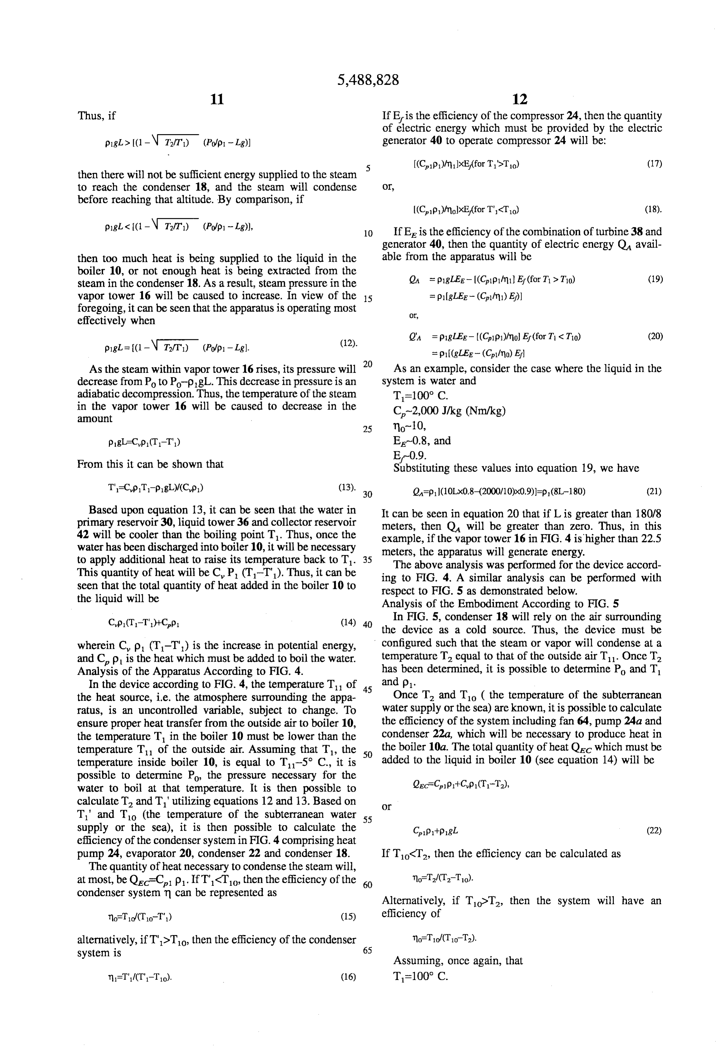
Thus, if If E is the efficiency of the compressor 24, then the quantity of electric energy which must be provided by the electric pig > (1 - N T2/T) (Pop - Lg)) generator 40 to operate compressor 24 will be: 5 (Cip1)/mi)xE,(for T'>To) (17) then there will not be sufficient energy supplied to the steam to reach the condenser 18, and the steam will condense Or, before reaching that altitude. By comparison, if
pigl < I(1-N Tft) (Pop 1 - Lg)), 10 If E is the efficiency of the combination of turbine 38 and generator 40, then the quantity of electric energy Q avail then too much heat is being supplied to the liquid in the able from the apparatus will be boiler 10, or not enough heat is being extracted from the OA = plgLEE-(Cplp1tm1 Ef (for T & To) (19) steam in the condenser 18. As a result, steam pressure in the vapor tower 16 will be caused to increase. In view of the 5 as p1 gLEE - (Clini) E)) foregoing, it can be seen that the apparatus is operating most Or, effectively when
pigl=(1-N T2/T) (Pop 1 - Lg). = p (gLEE- (Clfmo) El As the steam within vapor tower 16 rises, its pressure will 20 As an example, consider the case where the liquid in the decrease from Po to PopgL. This decrease in pressure is an system is water and adiabatic decompression. Thus, the temperature of the steam T=100° C.
in the vapor tower 16 will be caused to decrease in the C-2,000 J/kg (Nm/kg) anOIt
pgL=Cp (T-T) E-0.8, and
From this it can be shown that E-09.
Substituting these values into equation 19, we have
Based upon equation 13, it can be seen that the water in It can be seen in equation 20 that if L is greater than 180/8 primary reservoir 30, liquid tower 36 and collector reservoir meters, then Q will be greater than zero. Thus, in this 42 will be cooler than the boiling point T. Thus, once the example, if the vapor tower 16 in FIG. 4 is higher than 22.5 water has been discharged into boiler 10, it will be necessary meters, the apparatus will generate energy. to apply additional heat to raise its temperature back to T. 35 The above analysis was performed for the device accord This quantity of heat will be C. P. (T-T). Thus, it can be ing to FIG. 4. A similar analysis can be performed with seen that the total quantity of heat added in the boiler 10 to respect to FIG. 5 as demonstrated below. the liquid will be Analysis of the Embodiment According to FIG. 5 Cup (T1-T")+Cp (14) 40 In FIG. 5, condenser 18 will rely on the air surrounding the device as a cold source. Thus, the device must be wherein C. p. (T-T) is the increase in potential energy, configured such that the steam or vapor will condense at a temperature T equal to that of the outside air T. Once T.
and C. p is the heat which must be added to boil the water. has been determined,
Analysis of the Apparatus According to FIG. 4. it is possible to determine Po and T In the device according to FIG. 4, the temperature T of 45 and p1.
the heat source, i.e. the atmosphere surrounding the appa Once T and To ( the temperature of the subterranean ratus, is an uncontrolled variable, subject to change. To water supply or the sea) are known, it is possible to calculate ensure proper heat transfer from the outside air to boiler 10, the efficiency of the system including fan 64, pump 24a and the temperature T in the boiler 10 must be lower than the condenser 22a, which will be necessary to produce heat in temperature T of the outside air. Assuming that T, the 50 the boiler 10a. The total quantity of heat Q which must be temperature inside boiler 10, is equal to T-5° C., it is added to the liquid in boiler 10 (see equation 14) will be possible to determine Po the pressure necessary for the QecCapit-Cp (T-T), water to boil at that temperature. It is then possible to calculate T and T'utilizing equations 12 and 13. Based on Or
T' and To (the temperature of the subterranean water 55 supply or the sea), it is then possible to calculate the CipitpgL (22) efficiency of the condenser system in FIG. 4 comprising heat pump 24, evaporator 20, condenser 22 and condenser 18. If TogT, then the efficiency can be calculated as The quantity of heat necessary to condense the steam will, at most, be Qe=C. p. If Ti-To then the efficiency of the 60 condenser system n can be represented as
Alternatively, if TodT, then the system will have an no-fo/(To-T") (15) efficiency of alternatively, if T>To then the efficiency of the condenser flo-To/(To-T2).
system is 65
Assuming, once again, that n=T"ICT"-To). (16) T-100° C.
Page 14
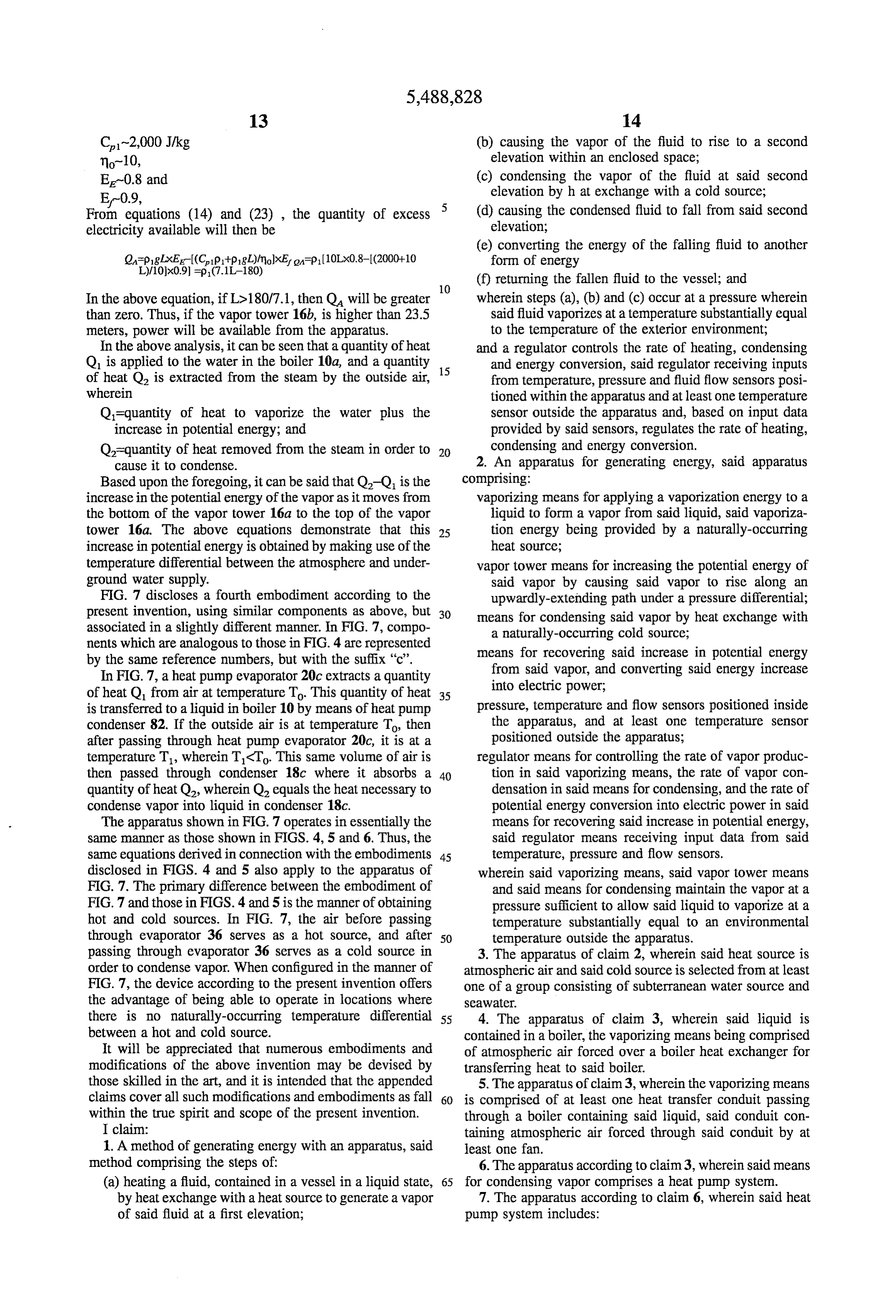
C-2,000 J/kg (b) causing the vapor of the fluid to rise to a second no-10, elevation within an enclosed space; E-0.8 and (c) condensing the vapor of the fluid at said second E-09, elevation by h at exchange with a cold source; From equations (14) and (23), the quantity of excess (d) causing the condensed fluid to fall from said second electricity available will then be elevation;
(e) converting the energy of the falling fluid to another form of energy
(f) returning the fallen fluid to the vessel; and
In the above equation, if L>180/7.1, then Q will be greater wherein steps (a), (b) and (c) occur at a pressure wherein than Zero. Thus, if the vapor tower 16b, is higher than 23.5 said fluid vaporizes at a temperature substantially equal meters, power will be available from the apparatus. to the temperature of the exterior environment; In the above analysis, it can be seen that a quantity of heat and a regulator controls the rate of heating, condensing Q is applied to the water in the boiler 10a, and a quantity 15 and energy conversion, said regulator receiving inputs of heat Q is extracted from the steam by the outside air, from temperature, pressure and fluid flow sensors posi wherein tioned within the apparatus and at least one temperature Q=quantity of heat to vaporize the water plus the sensor outside the apparatus and, based on input data increase in potential energy; and provided by said sensors, regulates the rate of heating, Q=quantity of heat removed from the steam in order to condensing and energy conversion. cause it to condense. 2. An apparatus for generating energy, said apparatus Based upon the foregoing, it can be said that Q-Q is the comprising:
increase in the potential energy of the vapor as it moves from vaporizing means for applying a vaporization energy to a the bottom of the vapor tower 16a to the top of the vapor liquid to form a vapor from said liquid, said vaporiza tower 16a. The above equations demonstrate that this 25 tion energy being provided by a naturally-occurring increase in potential energy is obtained by making use of the heat source;
temperature differential between the atmosphere and under vapor tower means for increasing the potential energy of ground water supply. said vapor by causing said vapor to rise along an FIG. 7 discloses a fourth embodiment according to the upwardly-extending path under a pressure differential; present invention, using similar components as above, but 30 means for condensing said vapor by heat exchange with associated in a slightly different manner. In FIG.7, compo a naturally-occurring cold source; nents which are analogous to those in FIG. 4 are represented means for recovering said increase in potential energy by the same reference numbers, but with the suffix "c'. from said vapor, and converting said energy increase In FIG. 7, a heat pump evaporator 20c extracts a quantity into electric power;
of heat Q, from air attemperature To. This quantity of heat 35 is transferred to a liquid in boiler 10 by means of heat pump pressure, temperature and flow sensors positioned inside condenser 82. If the outside air is at temperature To then the apparatus, and at least one temperature Sensor after passing through heat pump evaporator 20c, it is at a positioned outside the apparatus; temperature T, wherein TCT. This same volume of air is regulator means for controlling the rate of vapor produc then passed through condenser 18c where it absorbs a 40 tion in said vaporizing means, the rate of vapor con quantity of heat Q2, wherein Q2 equals the heat necessary to densation in said means for condensing, and the rate of condense vapor into liquid in condenser 18c. potential energy conversion into electric power in said The apparatus shown in FIG.7 operates in essentially the means for recovering said increase in potential energy, same manner as those shown in FIGS. 4, 5 and 6. Thus, the said regulator means receiving input data from said same equations derived in connection with the embodiments 45 temperature, pressure and flow sensors. disclosed in FIGS. 4 and 5 also apply to the apparatus of wherein said vaporizing means, said vapor tower means FIG. 7. The primary difference between the embodiment of and said means for condensing maintain the vapor at a FIG. 7 and those in FIGS. 4 and 5 is the manner of obtaining pressure sufficient to allow said liquid to vaporize at a hot and cold sources. In FIG. 7, the air before passing temperature substantially equal to an environmental through evaporator 36 serves as a hot source, and after 50 temperature outside the apparatus. passing through evaporator 36 serves as a cold source in 3. The apparatus of claim 2, wherein said heat source is order to condense vapor. When configured in the manner of atmospheric air and said cold source is selected from at least FIG. 7, the device according to the present invention offers one of a group consisting of subterranean water source and the advantage of being able to operate in locations where SeaWater.
there is no naturally-occurring temperature differential 55 4. The apparatus of claim 3, wherein said liquid is between a hot and cold source. contained in a boiler, the vaporizing means being comprised It will be appreciated that numerous embodiments and of atmospheric air forced over a boiler heat exchanger for modifications of the above invention may be devised by transferring heat to said boiler. those skilled in the art, and it is intended that the appended 5. The apparatus of claim3, wherein the vaporizing means claims cover all such modifications and embodiments as fall 60 is comprised of at least one heat transfer conduit passing within the true spirit and scope of the present invention. through a boiler containing said liquid, said conduit con I claim: taining atmospheric air forced through said conduit by at 1. A method of generating energy with an apparatus, said least one fan.
method comprising the steps of: 6. The apparatus according to claim3, wherein said means (a) heating a fluid, contained in a vessel in a liquid state, 65 for condensing vapor comprises a heat pump system. by heat exchange with a heat source to generate a vapor 7. The apparatus according to claim 6, wherein said heat of said fluid at a first elevation; pump system includes:
Page 15
a heat exchanger immersed in at least one of the group ranean water source whereby a naturally occurring tempera consisting of said seawater and said subterranean water ture differential may be realized.
SOurce, 18. The apparatus according to claim 17, wherein a flow an evaporator; of atmospheric air and a flow of a refrigerant associated with and heat transfer means for transferring heat from said a heat pump may be selectively controlled depending on the evaporator to said heat exchanger. temperature of the atmospheric air relative to at least one of 8. The apparatus according to claim 7, wherein said heat said subterranean water source and said seawater. transfer means includes a first conduit for permitting refrig 19. The apparatus according to claim 18, further com erant to pass from said heat exchanger to said evaporator, an prising refrigerant valves, wherein said flow of refrigerant is expansion valve placed between said first conduit and said 10 selectively controlled by said refrigerant valves so it may be evaporator, a second conduit for passing refrigerant from used to condense said vapor in said means for condensing, said evaporator to said heat exchanger and a compressor for and the flow of atmospheric air is selectively gated to said compressing said refrigerant as it passes from said evapo vaporizing means for vaporizing said liquid. rator to said heat exchanger.
9. The apparatus according to claim 2, wherein said vapor 15 20. The apparatus according to claim 18, further com tower means is comprised of an upwardly extending cham prising refrigerant valves, wherein said flow of refrigerant is ber attached at a lower end to a boiler in a gas tight manner selectively controlled by said refrigerant valves so said flow and attached at an upper end to a condenser in a gas-tight can be used to vaporize said liquid in said vaporizing means, mainer. and the flow of atmospheric air is selectively gated to said 10. The apparatus according to claim 2, wherein said 20 means for condensing said vapor for absorbing heat from means for recovering said increase in energy from said vapor said vapor.
and converting said energy increase into electric power is 21. The method according to claim 1, wherein said comprised of: heating comprises exchanging heat with atmospheric air; a primary reservoir for receiving condensed liquid from and said condensing comprising exchanging heat with at said means for condensing said vapor; 25 least one member of a group consisting of a subterranean a liquid tower attached in a liquid-tight manner to an water source and seawater, opening in a lower portion of said primary reservoir, 22. The method according to claim 21, wherein said said liquid tower extending downwardly from said heating comprises forcing the atmospheric air into a heat
exchanger which is in contact with the fluid to thereby turbine means mounted at a lower end of said liquid tower transfer heat from the atmospheric air to the fluid. for receiving liquid exiting said liquid tower; 23. The method according to claim 1, wherein said a generator operatively associated with said turbine condensing comprises exchanging heat with said cold source means, said generator being caused to produce energy by operating a heat pump.
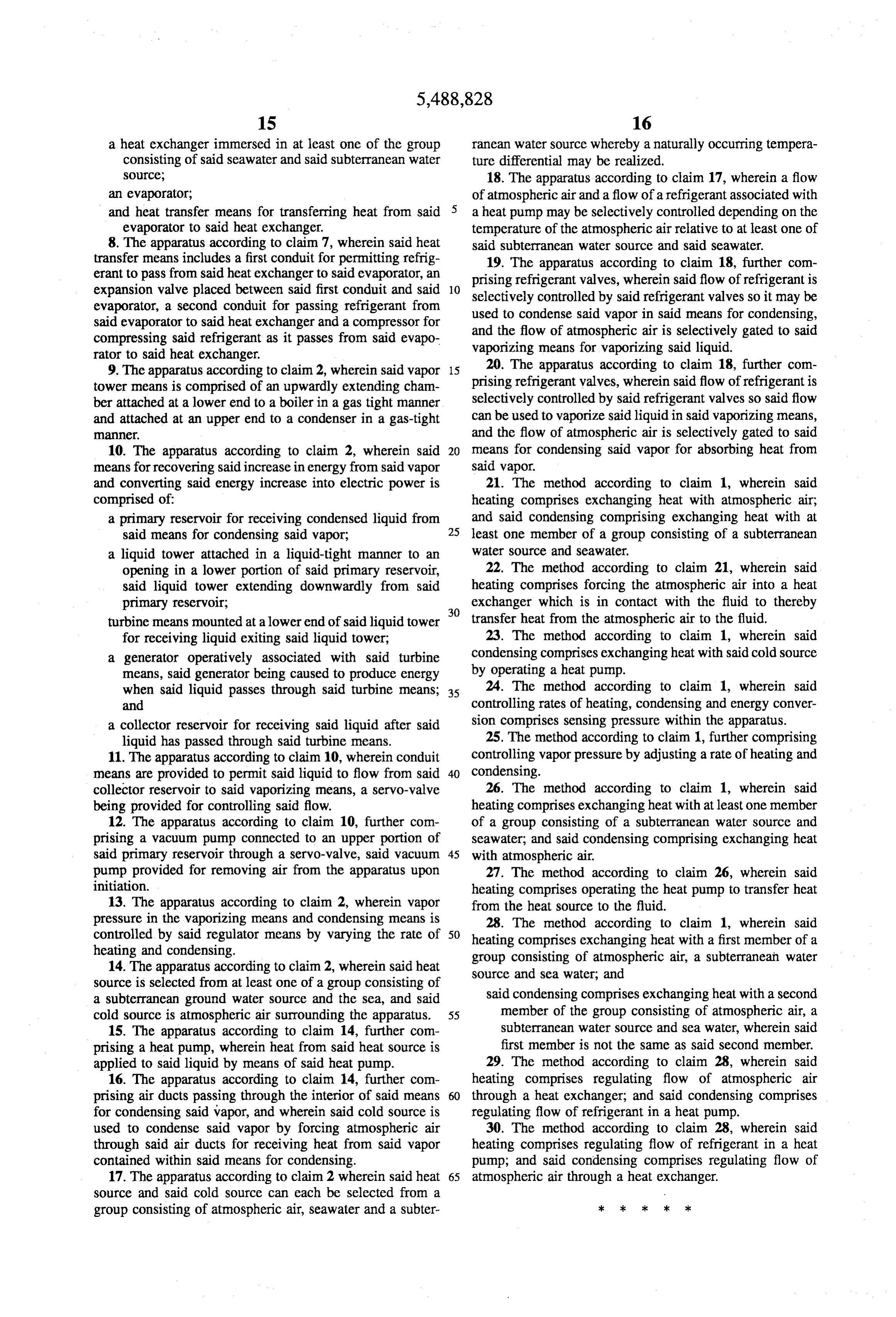
when said liquid passes through said turbine means; 35 24. The method according to claim 1, wherein said and controlling rates of heating, condensing and energy conver a collector reservoir for receiving said liquid after said sion comprises sensing pressure within the apparatus. liquid has passed through said turbine means. 25. The method according to claim 1, further comprising 11. The apparatus according to claim 10, wherein conduit controlling vapor pressure by adjusting a rate of heating and means are provided to permit said liquid to flow from said 40 condensing.
collector reservoir to said vaporizing means, a servo-valve 26. The method according to claim 1, wherein said being provided for controlling said flow. heating comprises exchanging heat with at least one member 12. The apparatus according to claim 10, further com of a group consisting of a subterranean water source and prising a vacuum pump connected to an upper portion of seawater, and said condensing comprising exchanging heat said primary reservoir through a servo-valve, said vacuum 45 with atmospheric air.
pump provided for removing air from the apparatus upon 27. The method according to claim 26, wherein said initiation. heating comprises operating the heat pump to transfer heat 13. The apparatus according to claim 2, wherein vapor from the heat source to the fluid. pressure in the vaporizing means and condensing means is 28. The method according to claim 1, wherein said controlled by said regulator means by varying the rate of 50 heating comprises exchanging heat with a first member of a heating and condensing. group consisting of atmospheric air, a subterranean water 14. The apparatus according to claim 2, wherein said heat Source and sea water, and source is selected from at least one of a group consisting of a subterranean ground water source and the sea, and said said condensing comprises exchanging heat with a second cold source is atmospheric air surrounding the apparatus. 55 member of the group consisting of atmospheric air, a 15. The apparatus according to claim 14, further com subterranean water source and sea water, wherein said prising a heat pump, wherein heat from said heat source is first member is not the same as said second member. applied to said liquid by means of said heat pump. 29. The method according to claim 28, wherein said 16. The apparatus according to claim 14, further com heating comprises regulating flow of atmospheric air prising air ducts passing through the interior of said means 60 through a heat exchanger; and said condensing comprises for condensing said vapor, and wherein said cold source is regulating flow of refrigerant in a heat pump. used to condense said vapor by forcing atmospheric air 30. The method according to claim 28, wherein said through said air ducts for receiving heat from said vapor heating comprises regulating flow of refrigerant in a heat contained within said means for condensing. pump; and said condensing comprises regulating flow of 17. The apparatus according to claim 2 wherein said heat 65 atmospheric air through a heat exchanger. source and said cold source can each be selected from a group consisting of atmospheric air, seawater and a subter ck k k k >
Provenance
- Collection
- Cited prior art
- Original PDF
- patentimages.storage.googleapis.com →
- Filed
- 1993-05-14
- Pages
- 15
- Method
- pdftotext (the PDF's own text layer) + pdftoppm 300dpi page scans
- Source
- Google Patents bibliographic record
- Granted
- 1996-02-06
- Inventors
- Pierre Brossard
- Transcribed from
- patentimages.storage.googleapis.com →