patent · US4193858
Stack pack electrolytic cell
18 March 1980
Page 1 — bibliographic record
United States Patent (19) 11 4,193,858 Loeffler, Jr. 45 Mar. 18, 1980 (54). STACK PACKELECTROLYTIC CELL FOREIGN PATENT DOCUMENTS (75) Inventor: J. Edward Loeffler, Jr., Kirtland, 429020 10/1974 U.S.S.R. ................................... 204/269
Primary Examiner-John H. Mack (73) Assignee: Diamond Shamrock Corporation, Assistant Examiner-D. R. Valentine Dallas, Tex. Attorney, Agent, or Firm-Bruce M. Winchell (21) Appl. No.: 957,324 (57) ABSTRACT (22 Filed: Nov. 3, 1978 Disclosed is a stack pack type electrolytic cell for the generation of chlorates or hypochlorites of sodium or 51) : Int. C.? .......... ........... C25B 9/04;C25B 11/03; potassium having the ability to make economical use of ;: . . . '.' C25B 11/00 materials while eliminating the necessity for large exter 52 U.S. C. .................................... 204/268; 204/270; nal studs for the electrode components, housings to 204/284; 204/290 R retain fluids and intercell piping connections since the 58) Field of Search ............... 204/267,268, 269,270, cell can be increased in capacity by adding chambers 204/284, 288, 289, 290 R, 95 and electrode stack packs to the cell makeup or adding (56) References Cited electrodes to the stack packs. Such an electrolyzer can utilize mass produced components to produce various
3,119,760 1/1964 Foreman et al........ 204/269 bipolar in configuration to make most efficient use of 3,819,504 6/1974 Bennett ........... ... 204/289 existing electrical supply equipment. 4,124,480 1 1/1978 Stevenson ............................ 204/268 4,134,805 1/1979 Fröhler et al. .................. 204/269 X 9 Claims, 6 Drawing Figures
runs
W Zip aaraaaaaaaaaaaaaaaaaaaaaaaaayaar vavvav Yava
Page 2
ove,
ZZZZZZZZZZZZZZZZZZZZZZZZZZZZZZZZZZZZZ
- -
set is e Ne Ns el's e Ne t T co : es e E. e N 2E s
S. CN
S go scN C
C O) O () S. (OO) O
S \, (oil. Toll. Oh,(O) of 000 OO OO go 1
I |9 (OO) () (OONC Go E (3) / (LUC) LTI (SAIL sy (O) r N CN
S co u-o co
Page 3
Drawing sheet — no readable text.
Page 4
Drawing sheet — no readable text.
Page 5
sary for any given operation. This, however, involves
STACK PACKELECTROLYTIC CELL inefficiencies of the use of materials such as electrode components in chambers and additional piping neces
BACKGROUND OF THE INVENTION sary for such cells to the extent where costs can rapidly The present invention relates generally to a stack exceed economical commercial realization of the full pack construction of an electrolytic cell for the genera potential of such an electrolytic chlorine generation tion of chlorates or hypochlorites of sodium or potas system because of the number of units associated equip sium utilizing repeatable components which are mass ment therewith, especially for large volume operations. produced to build electrolytic cells having various ca 10 Therefore, it would be exceedingly advantageous to pacities in addition to having either monopolar or bipo develop an electrolytic cell system for the generation of lar configurations for efficient use of existing electrical hypochlorite utilizing a brine solution that can be ade supply equipment. More particularly, the present inven quately sized for various production capacities and, in tion relates to an improved stack pack type electrolytic accordance with existing electrical supply equipment to cell for the production of sodium hypochlorite having 15 thereby reduce substantially the cost for the use of such repeatable enclosure and electrode stack pack compo cells in the production of water treatment compounds. nents which can be mass produced in the most efficient manner to build electrolytic cells of varying capacities SUMMARY OF THE INVENTION and varying electrode configurations. This employs the It is, therefore, an object of the present invention to use of two end plates with structural cross members 20 provide a stack pack electrolytic cell for the generation which can be utilized with tie rods between two such end plates to compress the chambers and stack packs of hypochlorite which can be built to varying capacities from mass produced components in either bipolar or therebetween. The various chambers which are utilized between these two end plates can be mass produced by economical configuration monopolar so as to provide the most injection molding or other plastic molding operations to given capacity of hypochlorite.for the generation of a cell construction provide a very uniform workpiece for the assembly of 25 These and other objects of the present invention, various sized electrolytic cells.
Active chlorine in the form of sodium hypochlorite together with the advantages thereof over existing and has been used for some time as a biocidally active agent skilledprior art forms which will become apparent to those for treatment of sewage, liquid effluents, water in swim in the art from the detailed disclosure of the ming pools, cooling tower waters, or drinking water. 30 present invention as set forth herein below, are accom Generally, such treatment is affected by the use of plished by the improvements herein shown, described rather large volumes of chemical compounds each as and claimed.
sodium hypochlorite or molecular chlorine, if available. It has been found that a stack pack electrolytic cell The addition of such chemical compounds to affect the for the production of chlorates or of hypochlorites can biocidal activity desired has become costly and is likely 35 consist of: two end plates having a plurality of struc that greater restrictions upon the traffic of dangerous tural cross members overhanging each edge of said end chemical products in the transportation networks of the plates for tying and compressing internal units therebe world will necessitate on-site manufacture of such com tween in liquid tight configuration; tie rods for extend pounds or a different means by which treatment may be ing and connecting the overextended edges of said carried out. For some time now, it has been known that structural cross members in order to compress the com electrochemical methods of manufacture present one ponents between said end plates; two or more chamber solution to this problem due to their capability for small sections in sealing engagement between said end plates; on-site production at a reasonable cost; greater ecologi at least one electrode stack pack; said electrode stack cal acceptability, and potential for energy conservation. pack containing at least one foraminous anode with an Furthermore, electrochemical methods of manufacture 45 can generally be operated as closed systems thereby electrocatalytically ber of cathodes active coating thereon and a num equal to the number of foraminous an allowing greater control over the escape of biproducts odes plus one; said cathodes or waste products from the electrolytic cells which may having apertures therein so asmade of metallic sheet have been environmentally undesirable. Electrolytic flow throughout said electrode stack pack; electrolyte to provide said cath cells promise to be one of the most efficient means of 50 odes acting as separators between said electrode stack utilizing electricity which is likely to be used more in packs to insure proper flow for cleaning the electrolytic the future due to the rapidly rising costs and expected cell of deposits; at least one access port for the removal exhaustion of fossil fuels such as coal, gas, and oil. of hydrogen gas from the electrolytic cell; and means Where there are readily available supplies of saltwa for providing a direct electrical current between said ter (brine) such as seawater, aqueous solutions of hypo anodes
chlorite solution can be readily made by electrolysis of rates orand said cathodes for the production of chlo hypochlorites.
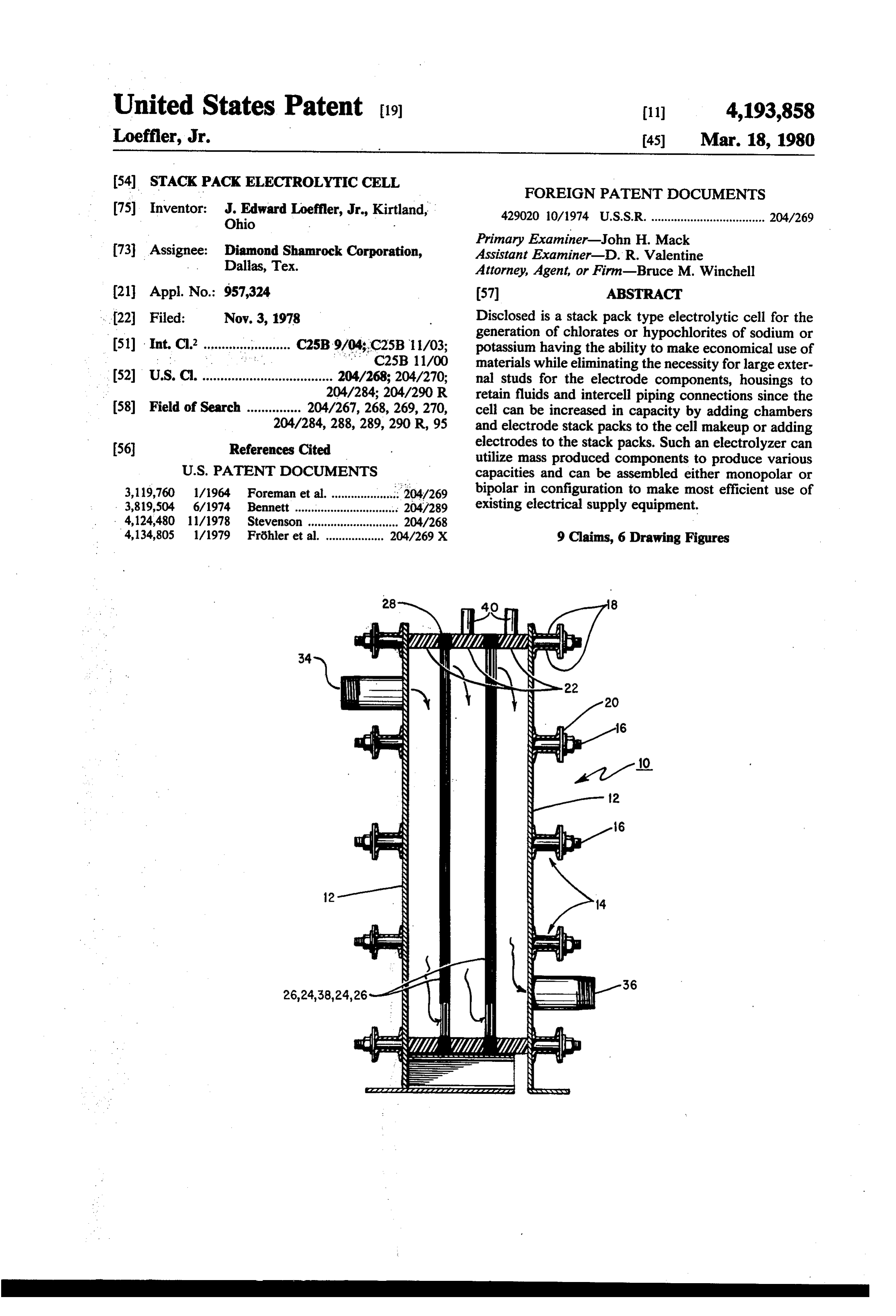
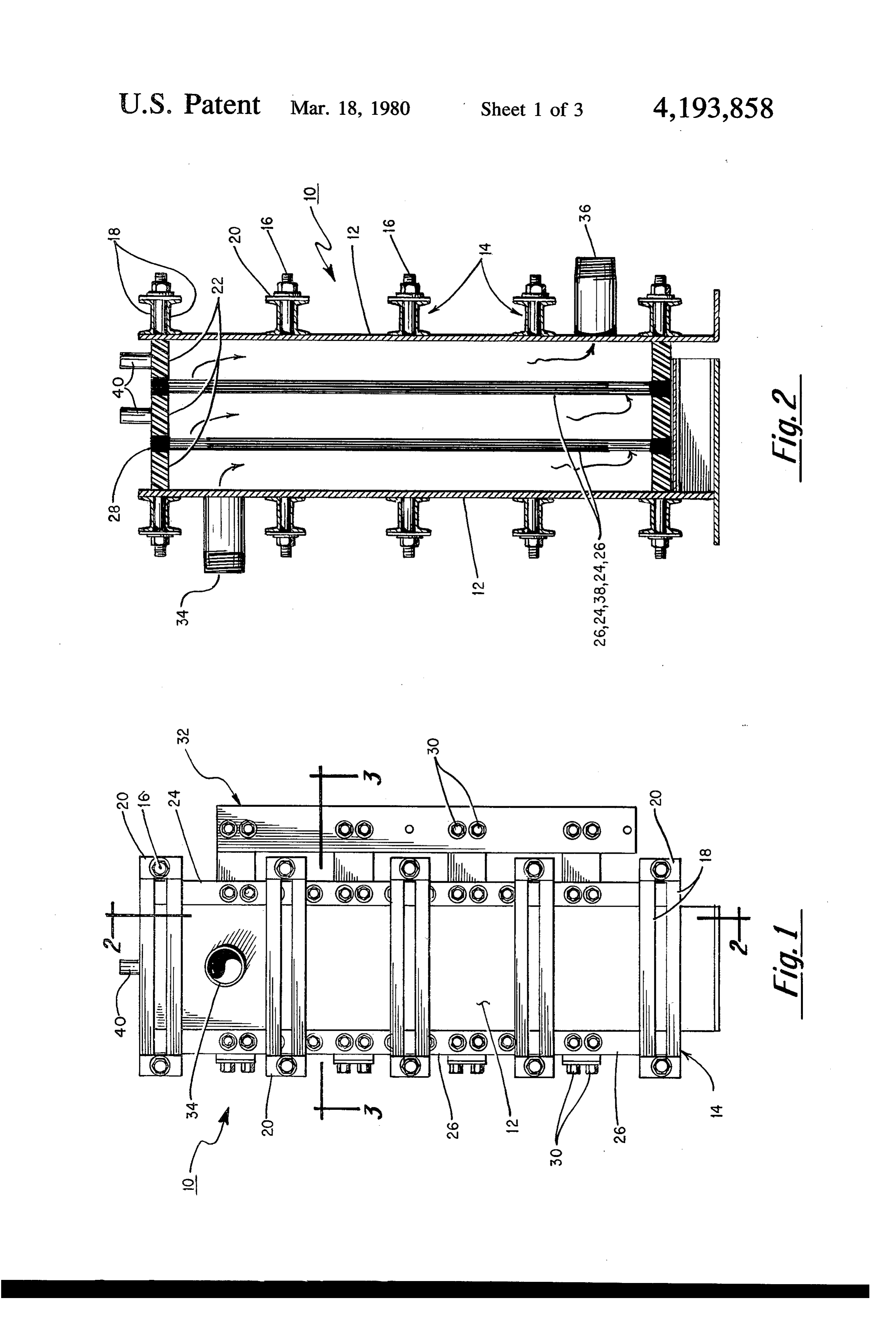
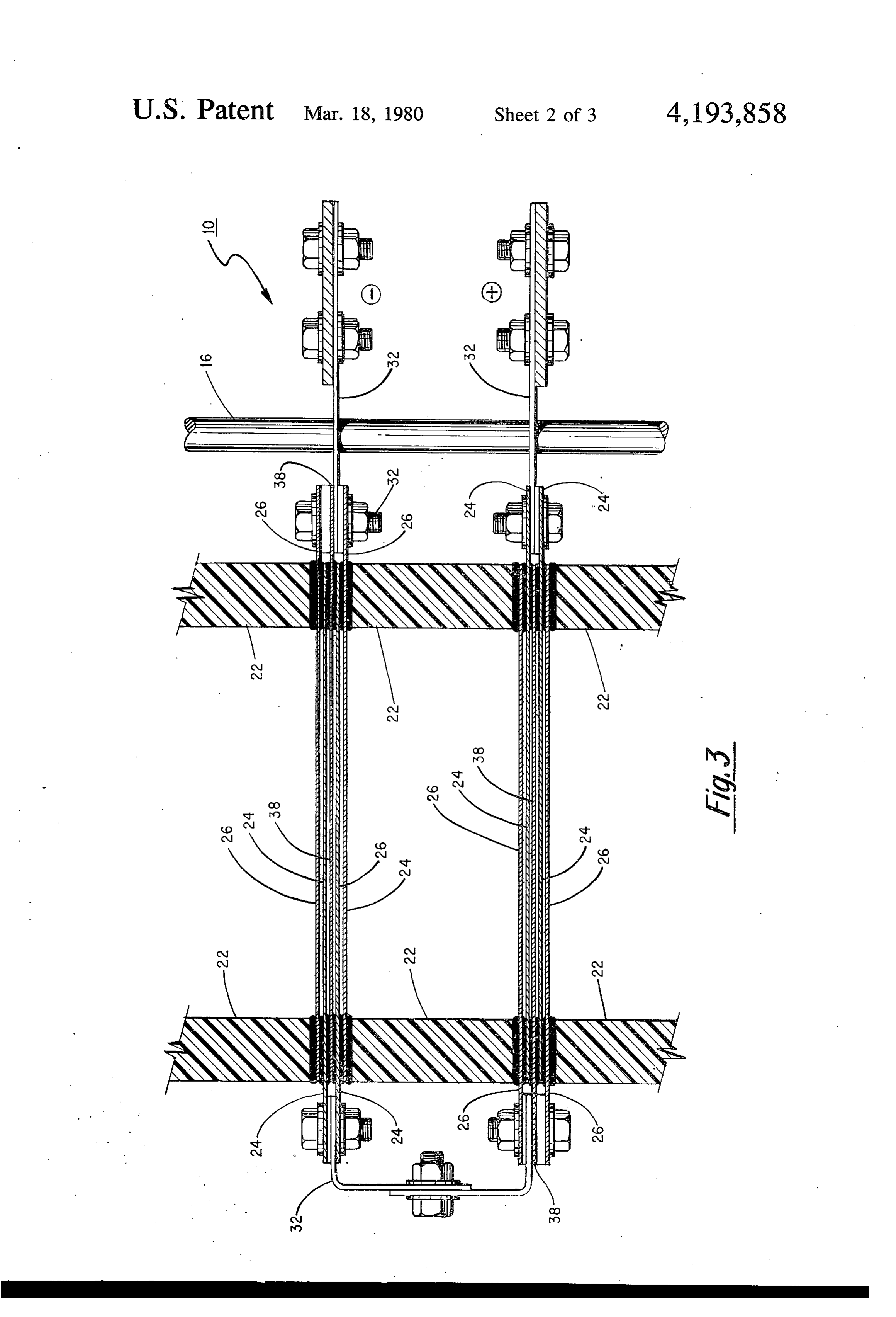
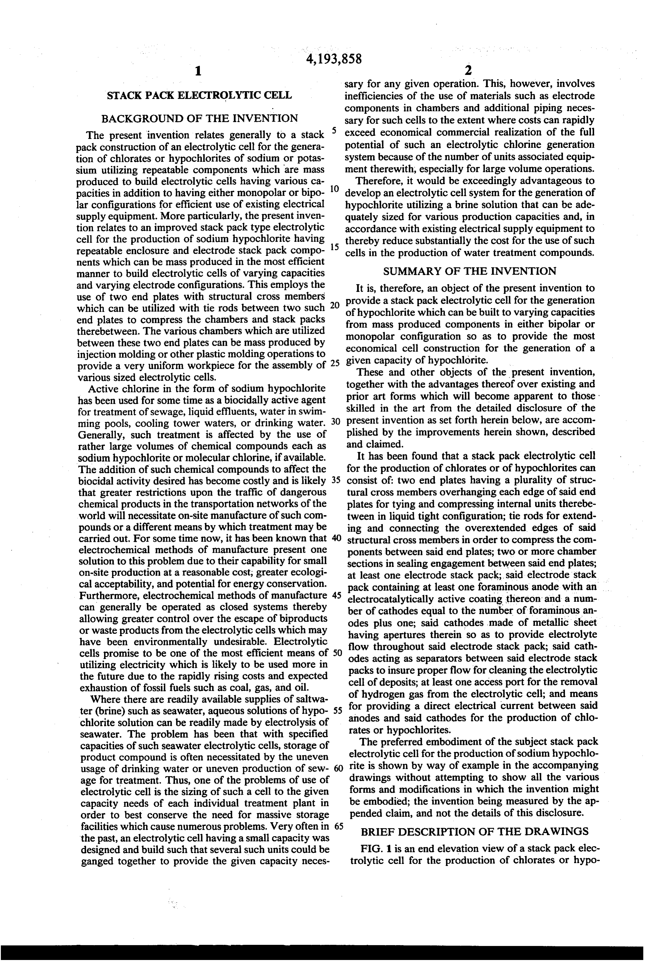
seawater. The problem has been that with specified The preferred embodiment of the subject stack pack capacities of such seawater electrolytic cells, storage of product compound is often necessitated by the uneven electrolytic cell for the production of sodium hypochlo usage of drinking water or uneven production of sew 60 rite is shown by way of example in the accompanying age for treatment. Thus, one of the problems of use of drawings without attempting to show all the various electrolytic cell is the sizing of such a cell to the given forms and modifications in which the invention might capacity needs of each individual treatment plant in be embodied; the invention being measured by the ap order to best conserve the need for massive storage pended claim, and not the details of this disclosure. facilities which cause numerous problems. Very often in 65 BRIEF DESCRIPTION OF THE DRAWINGS the past, an electrolytic cell having a small capacity was designed and build such that several such units could be FIG. 1 is an end elevation view of a stack pack elec ganged together to provide the given capacity neces trolytic cell for the production of chlorates or hypo
Page 6
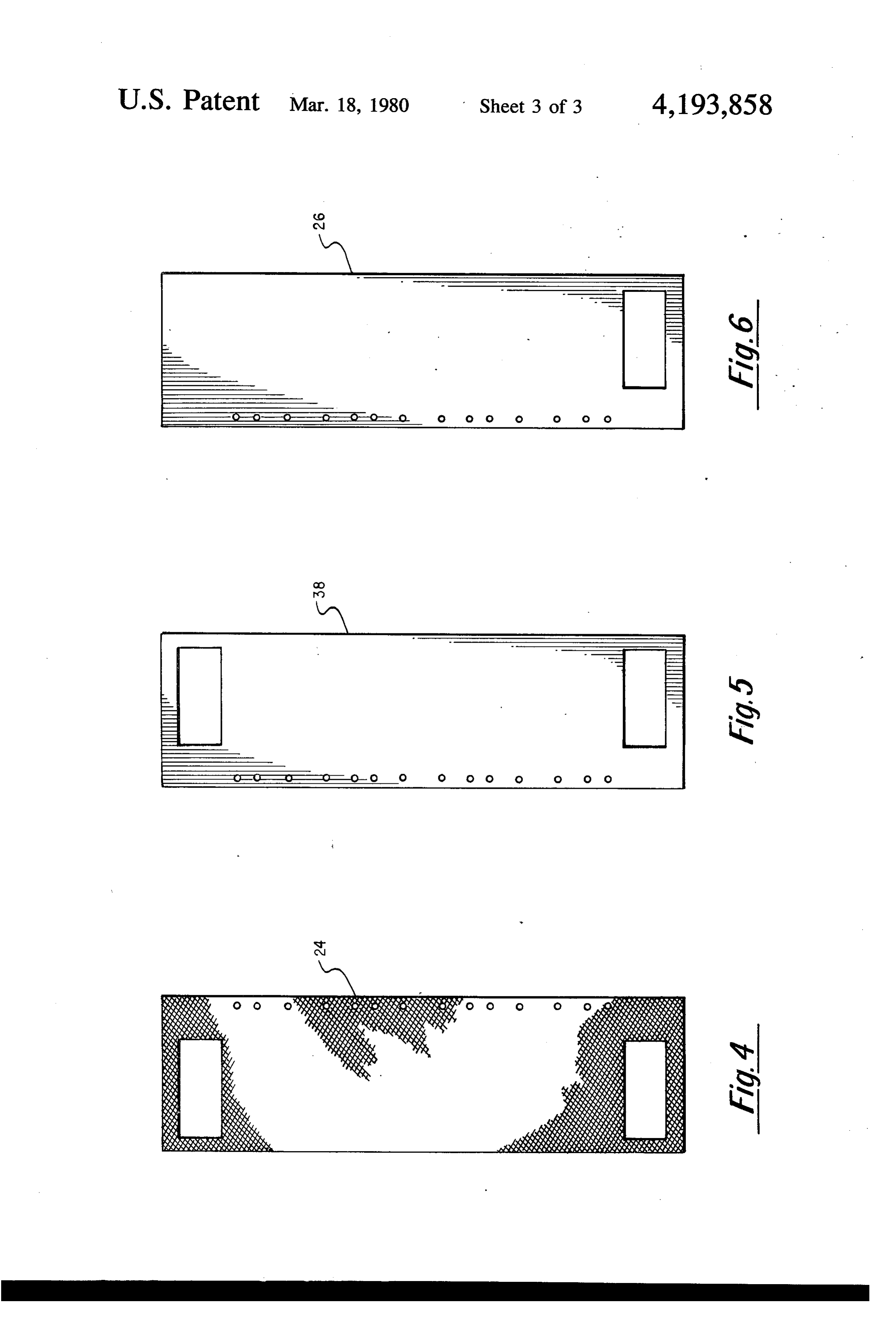
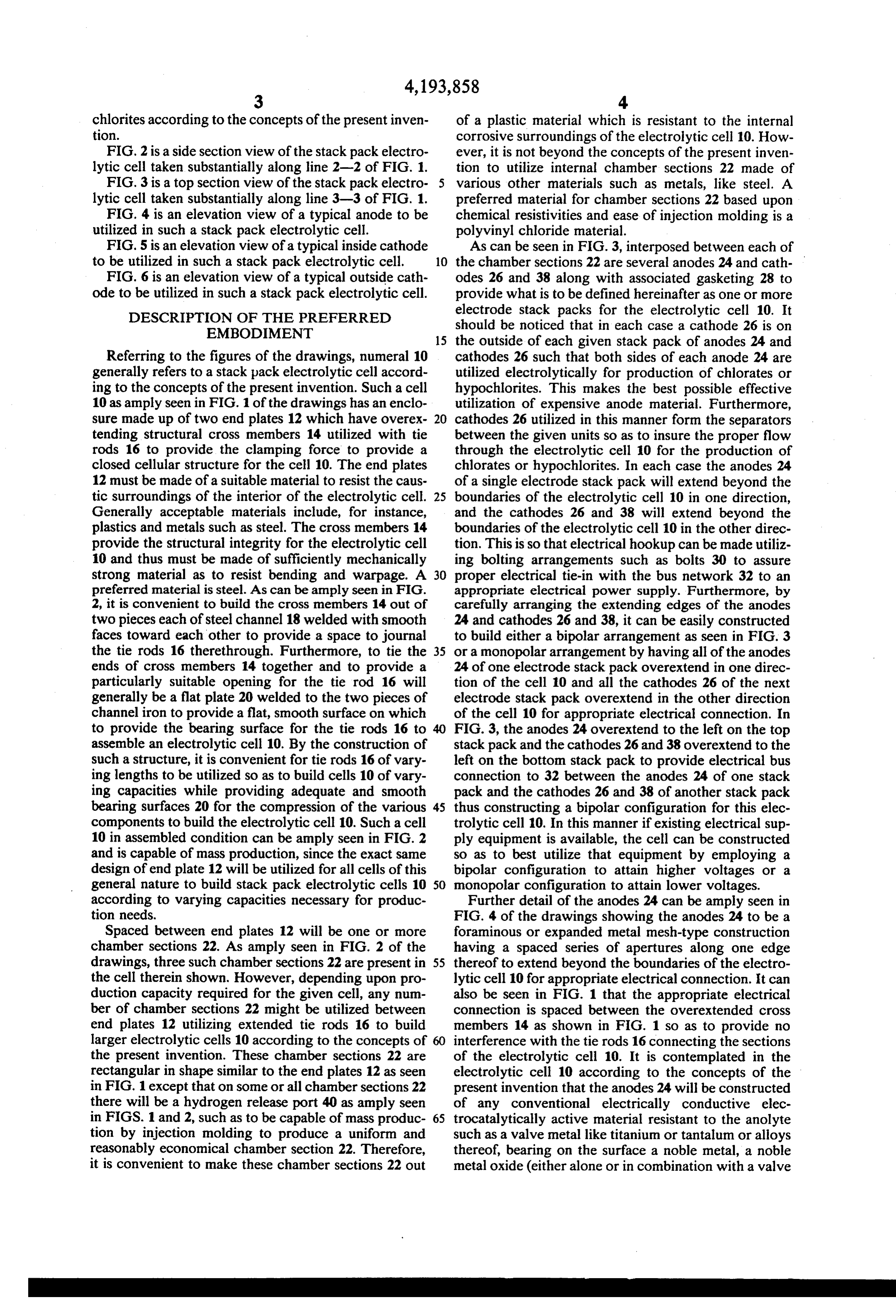
chlorites according to the concepts of the present inven of a plastic material which is resistant to the internal tion. corrosive surroundings of the electrolytic cell 10. How FIG. 2 is a side section view of the stack pack electro ever, it is not beyond the concepts of the present inven lytic cell taken substantially along line 2-2 of FIG. 1. tion to utilize internal chamber sections 22 made of FIG. 3 is a top section view of the stack pack electro various other materials such as metals, like steel. A lytic cell taken substantially along line 3-3 of FIG. 1. preferred material for chamber sections 22 based upon FIG. 4 is an elevation view of a typical anode to be chemical resistivities and ease of injection molding is a utilized in such a stack pack electrolytic cell. polyvinyl chloride material. FIG. 5 is an elevation view of a typical inside cathode As can be seen in FIG. 3, interposed between each of to be utilized in such a stack pack electrolytic cell. 10 the chamber sections 22 are several anodes 24 and cath FIG. 6 is an elevation view of a typical outside cath odes 26 and 38 along with associated gasketing 28 to ode to be utilized in such a stack pack electrolytic cell. provide what is to be defined hereinafter as one or more DESCRIPTION OF THE PREFERRED electrode stack packs for the electrolytic cell 10. It should be noticed that in each case a cathode 26 is on
EMBODIMENT 15 the outside of each given stack pack of anodes 24 and Referring to the figures of the drawings, numeral 10 cathodes 26 such that both sides of each anode 24 are generally refers to a stack pack electrolytic cell accord utilized electrolytically for production of chlorates or ing to the concepts of the present invention. Such a cell hypochlorites. This makes the best possible effective 10 as amply seen in FIG. 1 of the drawings has an enclo utilization of expensive anode material. Furthermore, sure made up of two end plates 12 which have overex 20 cathodes 26 utilized in this manner form the separators tending structural cross members 14 utilized with tie between the given units so as to insure the proper flow rods 16 to provide the clamping force to provide a through the electrolytic cell 10 for the production of closed cellular structure for the cell 10. The end plates chlorates or hypochlorites. In each case the anodes 24 12 must be made of a suitable material to resist the caus of a single electrode stack pack will extend beyond the tic surroundings of the interior of the electrolytic cell. 25 boundaries of the electrolytic cell 10 in one direction, Generally acceptable materials include, for instance, and the cathodes 26 and 38 will extend beyond the plastics and metals such as steel. The cross members 14 boundaries of the electrolytic cell 10 in the other direc provide the structural integrity for the electrolytic cell tion. This is so that electrical hookup can be made utiliz 10 and thus must be made of sufficiently mechanically ing bolting arrangements such as bolts 30 to assure strong material as to resist bending and warpage. A 30 proper electrical tie-in with the bus network 32 to an preferred material is steel. As can be amply seen in FIG. appropriate electrical power supply. Furthermore, by 2, it is convenient to build the cross members 14 out of carefully arranging the extending edges of the anodes two pieces each of steel channel 18 welded with smooth 24 and cathodes 26 and 38, it can be easily constructed faces toward each other to provide a space to journal to build either a bipolar arrangement as seen in FIG. 3 the tie rods 16 therethrough. Furthermore, to tie the 35 or a monopolar arrangement by having all of the anodes ends of cross members 14 together and to provide a 24 of one electrode stack pack overextend in one direc particularly suitable opening for the tie rod 16 will tion of the cell 10 and all the cathodes 26 of the next generally be a flat plate 20 welded to the two pieces of electrode stack pack overextend in the other direction channel iron to provide a flat, smooth surface on which of the cell 10 for appropriate electrical connection. In to provide the bearing surface for the tie rods 16 to 40 FIG. 3, the anodes 24 overextend to the left on the top assemble an electrolytic cell 10. By the construction of stack pack and the cathodes 26 and 38 overextend to the such a structure, it is convenient for tie rods 16 of vary left on the bottom stack pack to provide electrical bus ing lengths to be utilized so as to build cells 10 of vary connection to 32 between the anodes 24 of one stack ing capacities while providing adequate and smooth pack and the cathodes 26 and 38 of another stack pack bearing surfaces 20 for the compression of the various 45 thus constructing a bipolar configuration for this elec components to build the electrolytic cell 10. Such a cell trolytic cell 10. In this manner if existing electrical sup 10 in assembled condition can be amply seen in FIG. 2 ply equipment is available, the cell can be constructed and is capable of mass production, since the exact same so as to best utilize that equipment by employing a design of end plate 12 will be utilized for all cells of this bipolar configuration to attain higher voltages or a general nature to build stack pack electrolytic cells 10 50 monopolar configuration to attain lower voltages. according to varying capacities necessary for produc Further detail of the anodes 24 can be amply seen in tion needs. FIG. 4 of the drawings showing the anodes 24 to be a Spaced between end plates 12 will be one or more foraminous or expanded metal mesh-type construction chamber sections 22. As amply seen in FIG. 2 of the having a spaced series of apertures along one edge drawings, three such chamber sections 22 are present in 55 thereof to extend beyond the boundaries of the electro the cell therein shown. However, depending upon pro lytic cell 10 for appropriate electrical connection. It can duction capacity required for the given cell, any num also be seen in FIG. 1 that the appropriate electrical ber of chamber sections 22 might be utilized between connection is spaced between the overextended cross end plates 12 utilizing extended tie rods 16 to build members 14 as shown in FIG. 1 so as to provide no larger electrolytic cells 10 according to the concepts of 60 interference with the tie rods 16 connecting the sections the present invention. These chamber sections 22 are of the electrolytic cell 10. It is contemplated in the rectangular in shape similar to the end plates 12 as seen electrolytic cell 10 according to the concepts of the in FIG. 1 except that on some or all chamber sections 22 present invention that the anodes 24 will be constructed there will be a hydrogen release port 40 as amply seen of any conventional electrically conductive elec in FIGS. 1 and 2, such as to be capable of mass produc 65 trocatalytically active material resistant to the anolyte tion by injection molding to produce a uniform and such as a valve metal like titanium or tantalum or alloys reasonably economical chamber section 22. Therefore, thereof, bearing on the surface a noble metal, a noble it is convenient to make these chamber sections 22 out metal oxide (either alone or in combination with a valve
Page 7
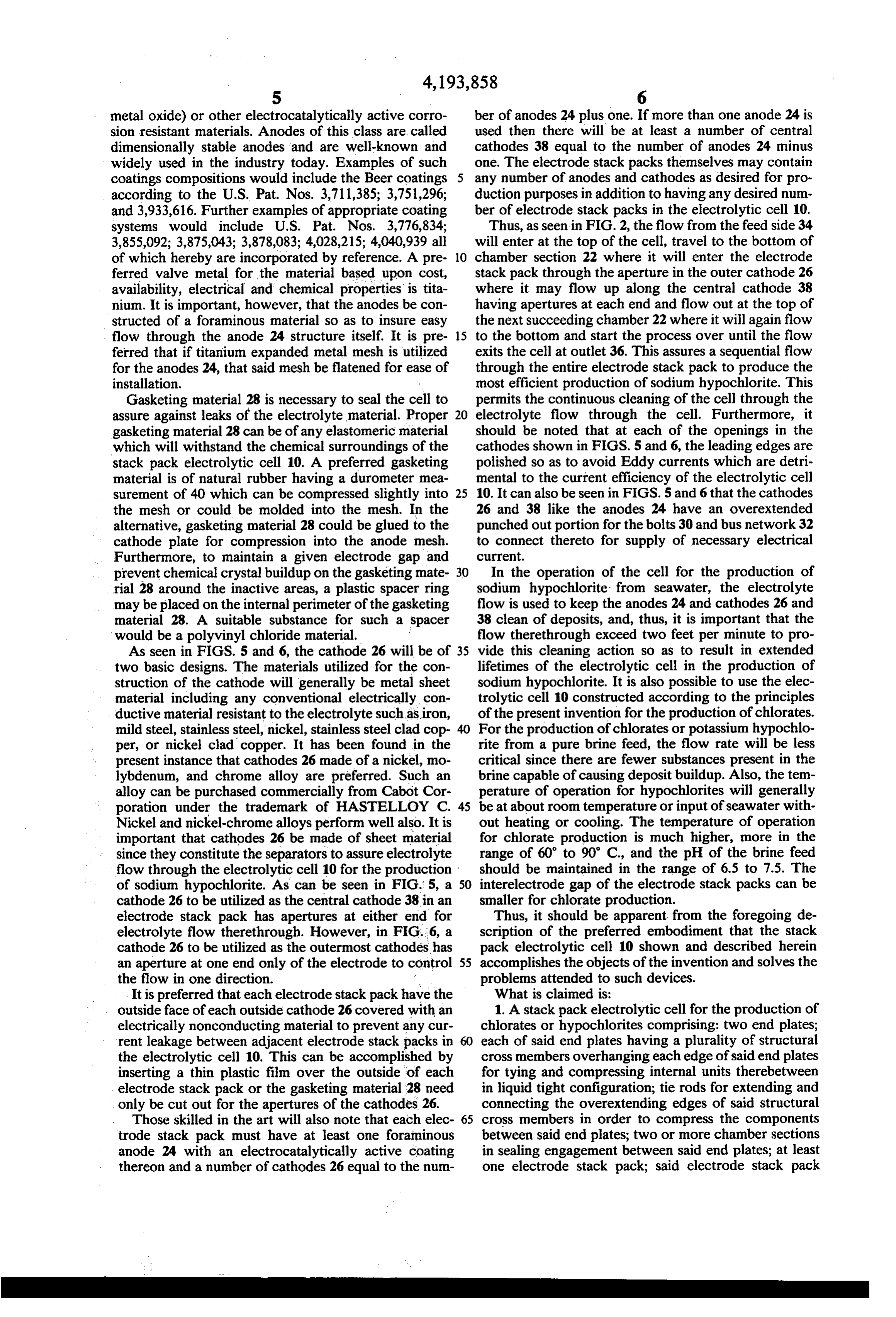
metal oxide) or other electrocatalytically active corro ber of anodes 24 plus one. If more than one anode 24 is sion resistant materials. Anodes of this class are called used then there will be at least a number of central dimensionally stable anodes and are well-known and cathodes 38 equal to the number of anodes 24 minus widely used in the industry today. Examples of such one. The electrode stack packs themselves may contain coatings compositions would include the Beer coatings any number of anodes and cathodes as desired for pro according to the U.S. Pat. Nos. 3,711,385; 3,751,296; duction purposes in addition to having any desired num and 3,933,616. Further examples of appropriate coating ber of electrode stack packs in the electrolytic cell 10. systems would include U.S. Pat. Nos. 3,776,834; Thus, as seen in FIG. 2, the flow from the feed side 34 3,855,092; 3,875,043; 3,878,083; 4,028,215; 4,040,939 all will enter at the top of the cell, travel to the bottom of of which hereby are incorporated by reference. A pre 10 chamber section 22 where it will enter the electrode ferred valve metal for the material based upon cost, stack pack through the aperture in the outer cathode 26 availability, electrical and chemical properties is tita where it may flow up along the central cathode 38 nium. It is important, however, that the anodes be con having apertures at each end and flow out at the top of structed of a foraminous material so as to insure easy the next succeeding chamber 22 where it will again flow flow through the anode 24 structure itself. It is pre 15 to the bottom and start the process over until the flow ferred that if titanium expanded metal mesh is utilized exits the cell at outlet 36. This assures a sequential flow for the anodes 24, that said mesh be flatened for ease of through the entire electrode stack pack to produce the installation. most efficient production of sodium hypochlorite. This Gasketing material 28 is necessary to seal the cell to permits the continuous cleaning of the cell through the assure against leaks of the electrolyte material. Proper 20 electrolyte flow through the cell. Furthermore, it gasketing material 28 can be of any elastomeric material should be noted that at each of the openings in the which will withstand the chemical surroundings of the cathodes shown in FIGS. 5 and 6, the leading edges are stack pack electrolytic cell 10. A preferred gasketing polished so as to avoid Eddy currents which are detri material is of natural rubber having a durometer mea mental to the current efficiency of the electrolytic cell surement of 40 which can be compressed slightly into 25 10. It can also be seen in FIGS. 5 and 6 that the cathodes the mesh or could be molded into the mesh. In the 26 and 38 like the anodes 24 have an overextended alternative, gasketing material 28 could be glued to the punched out portion for the bolts 30 and bus network 32 cathode plate for compression into the anode mesh. to connect thereto for supply of necessary electrical Furthermore, to maintain a given electrode gap and current.
prevent chemical crystal buildup on the gasketing mate 30 In the operation of the cell for the production of rial 28 around the inactive areas, a plastic spacer ring sodium hypochlorite from seawater, the electrolyte may be placed on the internal perimeter of the gasketing flow is used to keep the anodes 24 and cathodes 26 and material 28. A suitable substance for such a spacer 38 clean of deposits, and, thus, it is important that the would be a polyvinyl chloride material. flow therethrough exceed two feet per minute to pro As seen in FIGS. 5 and 6, the cathode 26 will be of 35 vide this cleaning action so as to result in extended two basic designs. The materials utilized for the con lifetimes of the electrolytic cell in the production of struction of the cathode will generally be metal sheet sodium hypochlorite. It is also possible to use the elec material including any conventional electrically con trolytic cell 10 constructed according to the principles ductive material resistant to the electrolyte such as iron, of the present invention for the production of chlorates. mild steel, stainless steel, nickel, stainless steel clad cop For the production of chlorates or potassium hypochlo per, or nickel clad copper. It has been found in the rite from a pure brine feed, the flow rate will be less present instance that cathodes 26 made of a nickel, mo critical since there are fewer substances present in the lybdenum, and chrome alloy are preferred. Such an brine capable of causing deposit buildup. Also, the tem alloy can be purchased commercially from Cabot Cor perature of operation for hypochlorites will generally poration under the trademark of HASTELLOY C. 45 be at about room temperature or input of seawater with Nickel and nickel-chrome alloys perform well also. It is out heating or cooling. The temperature of operation important that cathodes 26 be made of sheet material for chlorate production is much higher, more in the since they constitute the separators to assure electrolyte range of 60 to 90° C., and the pH of the brine feed flow through the electrolytic cell 10 for the production should be maintained in the range of 6.5 to 7.5. The of sodium hypochlorite. As can be seen in FIG. 5, a 50 interelectrode gap of the electrode stack packs can be cathode 26 to be utilized as the central cathode 38 in an smaller for chlorate production.
electrode stack pack has apertures at either end for Thus, it should be apparent from the foregoing de electrolyte flow therethrough. However, in FIG.6, a scription of the preferred embodiment that the stack cathode 26 to be utilized as the outermost cathodes has pack electrolytic cell 10 shown and described herein an aperture at one end only of the electrode to control 55 accomplishes the objects of the invention and solves the the flow in one direction. problems attended to such devices. It is preferred that each electrode stack pack have the What is claimed is:
outside face of each outside cathode 26 covered with an 1. A stack pack electrolytic cell for the production of electrically nonconducting material to prevent any cur chlorates or hypochlorites comprising: two end plates; rent leakage between adjacent electrode stack packs in each of said end plates having a plurality of structural the electrolytic cell 10. This can be accomplished by cross members overhanging each edge of said end plates inserting a thin plastic film over the outside of each for tying and compressing internal units therebetween electrode stack pack or the gasketing material 28 need in liquid tight configuration; tie rods for extending and only be cut out for the apertures of the cathodes 26. connecting the overextending edges of said structural Those skilled in the art will also note that each elec 65 cross members in order to compress the components trode stack pack must have at least one foraminous between said end plates; two or more chamber sections anode 24 with an electrocatalytically active coating in sealing engagement between said end plates; at least thereon and a number of cathodes 26 equal to the num one electrode stack pack; said electrode stack pack
Page 8
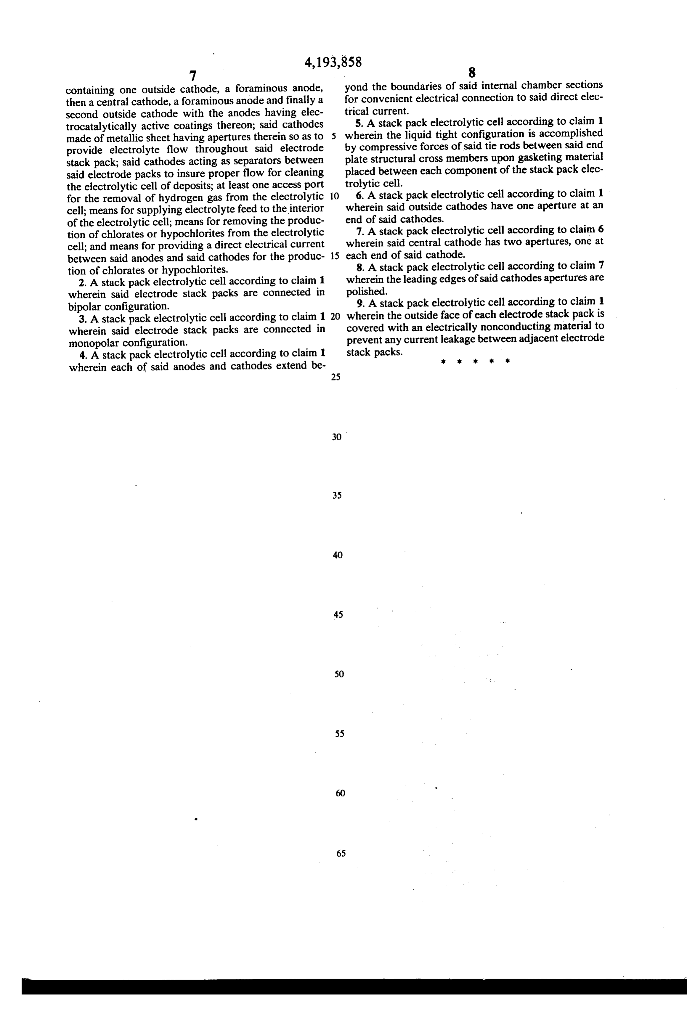
containing one outside cathode, a foraminous anode, yond the boundaries of said internal chamber sections then a central cathode, a foraminous anode and finally a for convenient electrical connection to said direct elec second outside cathode with the anodes having elec trical current.
trocatalytically active coatings thereon; said cathodes wherein5. A stack pack electrolytic cell according to claim 1 made of metallic sheet having apertures therein so as to the liquid tight configuration is accomplished provide electrolyte flow throughout said electrode by compressive forces of said tie rods between said end stack pack; said cathodes acting as separators between plate structural cross members upon gasketing material said electrode packs to insure proper flow for cleaning placed between each component of the stack pack elec the electrolytic cell of deposits; at least one access port trolytic cell.
for the removal of hydrogen gas from the electrolytic 10 6. A stack pack electrolytic cell according to claim 1 cell; means for supplying electrolyte feed to the interior wherein said outside cathodes have one aperture at an of the electrolytic cell; means for removing the produc end of said cathodes.
tion of chlorates or hypochlorites from the electrolytic 7. A stack pack electrolytic cell according to claim 6 cell; and means for providing a direct electrical current wherein said central cathode has two apertures, one at between said anodes and said cathodes for the produc 15 each end of said cathode.
8. A stack pack electrolytic cell according to claim 7 tion of chlorates or hypochlorites.
2. A stack pack electrolytic cell according to claim 1 wherein the leading edges of said cathodes apertures are wherein said electrode stack packs are connected in polished. 9. A stack pack electrolytic cell according to claim 1 bipolar configuration.
3. A stack pack electrolytic cell according to claim 1 20 wherein the outside face of each electrode stack pack is wherein said electrode stack packs are connected in covered with an electrically nonconducting material to prevent any current leakage between adjacent electrode monopolar configuration.
4. A stack pack electrolytic cell according to claim 1 stack packs. k wherein each of said anodes and cathodes extend be
Provenance
- Collection
- Cited prior art
- Original PDF
- patentimages.storage.googleapis.com →
- Filed
- 1978-11-03
- Pages
- 8
- Method
- pdftotext (the PDF's own text layer) + pdftoppm 300dpi page scans
- Source
- Google Patents bibliographic record
- Granted
- 1980-03-18
- Inventors
- J. Edward Loeffler, Jr.; Diamond Shamrock Corp
- Transcribed from
- patentimages.storage.googleapis.com →