patent · US3495925
Combination igniter and temperature sensor
17 February 1970
Page 1
Drawing sheet — no readable text.
Page 2
United States Patent Office 3,495,925 Patented Feb. 17, 1970
an igniter in a coaxial assembly with a temperature sensor 3,495,925 for proving the temperature of the igniter. COMBINATION IGNTER AND TEMPERATURE The present invention has another object in that a com
SENSOR
James R. Wilson, Garden Grove, Calif., assignor to bination igniter and flame sensor is constructed in a Robertshaw Controls Company, Richmond, Va., a coaxial assembly.
corporation of Delaware The present invention is characterized in that a com Filed June 11, 1968, Ser. No. 736,205 bined igniting and temperature sensing device includes an Int. CI. F23n 5/02; F23q 2/28 insulating casing, an igniting coil would around the casing, U.S. CI. 431-66 10 Claims a conductor disposed within the casing and a thermistor 10 disposed within the casing and connected with the con
ABSTRACT OF THE DISCLOSURE Other objects and advantages of the present invention A combination igniter and temperature sensor com will become apparent from the following description of prising a coaxial assembly having an inner conductor ex 5 the preferred embodiments as shown in the accompany ing drawings.
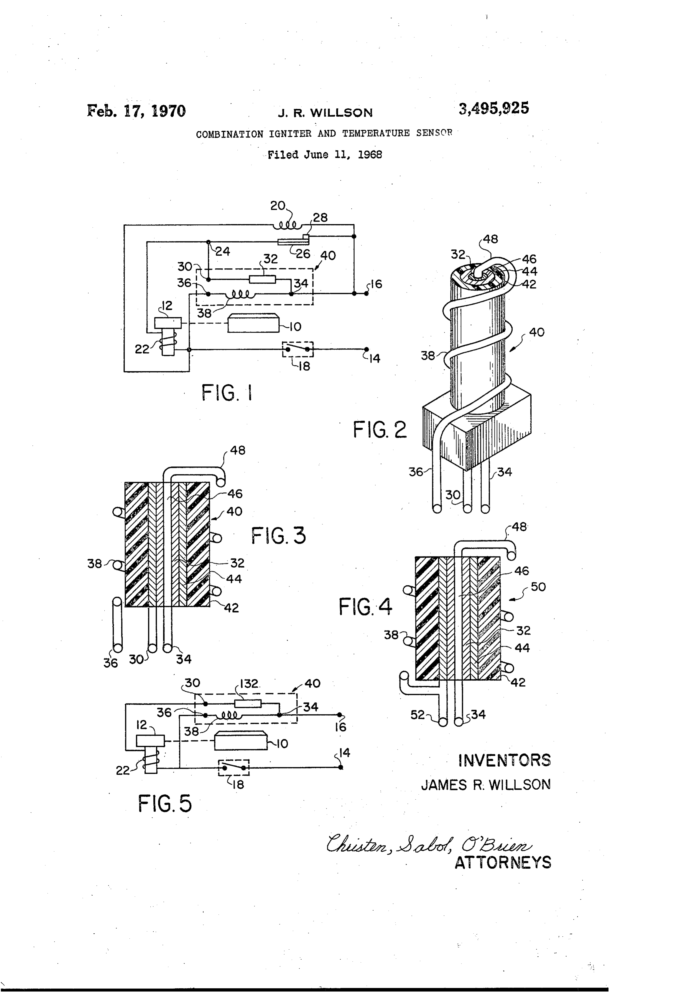
tending through the center of the coaxial assembly, a ring of thermistor material concentrically surrounding the BRIEF DESCRIPTION OF THE DRAWINGS inner conductor, an outer conductor concentrically sur rounding the ring of thermistor material, a sheath of in FIG. 1 is a schematic diagram of a burner control sulating material concentrically surrounding the outer System utilizing a combined igniter and temperature conductor, and an igniting coil wound around the sheath 20 sensor in accordance with the present invention; FIG. 2 is a perspective view of a three terminal com and connected to the inner conductor at the top of the bination igniter and temperature sensor in accordance assembly.
with the present invention;
BACKGROUND OF THE INVENTION FIG. 3 is a side elevation with parts in section of the 25 coaxial assembly of the three terminal combination igniter
The present invention pertains to an igniter for fuel and temperature sensor shown in FIG. 2; burner apparatus and more particularly to a combination FIG. 4 is a side elevation with parts in section of a two igniter and temperature sensor for use in controlling terminal combination igniter and temperature sensor in burner apparatus. accordance with the present invention; and Conventional automatic ignition and safety shut-off 30 FIG. 5 is a schematic diagram of a burner control sys apparatus for burners include standing pilots, and electric tem utilizing the combination igniter and temperature igniters. Systems using a standing pilot and a thermo Sensor of FIGS. 2 and 3.
couple for sensing the pilot flame have the disadvantage DESCRIPTION OF THE PREFERIRED of being subject to drafts, high ambient temperatures and EMBODIMENT clogging from lint and dust. Electric igniters have been 35 used for indirect ignition by igniting a pilot and direct A burner control system using a three terminal com ingition, Indirect ignition using electric igniters has the bination igniter and temperature sensor according to the same disadvantages as the standing pilot systems and, present invention is shown in FIG. 1 and includes a burner consequently, direct ignition is the most desirable. In the 40 10 having a flow of fuel thereto under the control of a past, complex circuitry has been necessary in order to valve 12. A pair of power leads 14 and 16 are adapted prove the flame or ignition temperature of the electric to be connected to any suitable conventional source of igniter in direct ignition systems, and the electric igniter electrical energy. Lead 14 is connected through a switch and the flame sensing means or ignition temperature 18 and a heating coil 20 to lead 16 and through switch proving means have been separate units causing difficulty 45 18 and a Solenoid 22 for valve 12 to a junction 24 which in installation and repair. connects with lead 16 through the parallel combination SUMMARY OF THE INVENTION of a bimetal element 26 and a contact 28 in series and a terminal 30, a thermistor 32 and a terminal 34. Lead 14
Accordingly, an object of the present invention is to also connects with lead 16 through switch 18, a terminal construct a single device operable as both an igniter and 50 36, an electric igniter 38 and terminal 34. Thermistor 32 a temperature sensor. and igniter 38 are formed in a single device 40 which is A further object of the present invention is to combine located within igniting and flame sensing proximity of an igniter and a temperature sensor in a single coaxial burner 10.
assembly. In order to simplify the description of the operation of Another object of the present invention is to construct 55 of FIG. 1, it is being described in conjunction with a a combination igniter and temperature sensor having only heating System; however, the present invention has many three terminals. uses in many systems and is not intended to be limited The present invention has another object in that a com to heating systems. Switch 18 may be an automatic bination igniter and temperature sensor is constructed thermostat, or it may be manually operated. In either having only two terminals. 60 case, when heat is desired switch 18 is closed to energize Another object of the present invention is to assemble a igniter 38 and cause current to flow through heating coil dual function device having a thermistor disposed within 20. Due to the negative temperature coefficient of therm an igniting coil. istor 32, it exhibits an extremely high resistance and is Yet another object of the present invention is to utilize effectively nonconducting before burner 10 is ignited; a single device as an igniter and an igniter proving means. 65 however, Solenoir 22 is energized to open valve 12 due A further object of the present invention is to construct to the current path through bimetal 26 and contact 28.
Page 3
After igniter 38 heats to igniting temperature, burner 10 temperature for substantial conduction, it presents a high is ignited, and thermistor 32 senses the flame at burner resistance. Igniter coil 38 is connected at one end to ter 10 which lowers its resistance to allow it to conduct and minal 36 and at its other end to terminal 34 through provide a current path to maintain valve 12 open after inner conductor 46.
bimetal 26 warps to open contact 28 due to the heat from A modification of the embodiment of FIGS. 2 and 3 coil 20. With proper ignition, the system will now be in is illustrated in FIG. 4, and identical reference numerals its full heating condition in which igniter 38 is energized, are employed in FIG. 4 to designate parts identical to thermistor 32 is conducting, valve 12 is open, and con FIGS. 2 and 3.
tact 28 is open. The system will continue in its full heating FIG. 4 illustrates an embodiment of the combination condition until switch 18 is opened; however, should the O igniter and temperature sensor of the present invention used as a parallel resistance-operated device 50. Device flame at burner 10 be extinguished for some reason, thermistor 32 will become nonconducting to deemergize 50 is identical in structure to device 40 except that only solenoid 22 and close valve 12 and place the system in a two terminals 34 and 52 are provided with terminal 52 lock-out condition. To reset the system from its lock-out connected to both igniter 38 and conductor 44. The con condition, switch 18 is opened and then closed again nection of both igniter 38 and conductor 44 to terminal after heating coil 20 has cooled sufficiently to allow bi 52 places igniter 38 and thermistor 32 in parallel between metal 26 and contact 28 to close. terminals 52 and 34, and their parallel network resistance If, after switch 18 is closed, ignition does not occur may be used as a control means.
by the time bimetal 26 is heated sufficiently to warp and For example, when used in a flame proving burner con move away from contact 28, thermistor 32 will remain 20 trol System, igniter 38 may be a tungsten glow-wire having nonconducting to deemergize solenoid 22 and close valve a resistance of 150 ohms at ignition temperature and 25 12 to stop the flow of fuel to burner 10. The system will ohms at room temperature, and thermistor 32 may have now be in its lock-out condition which requires opening an extremely high resistance when not exposed to a flame of switch 18 for resetting as previously explained. and a resistance of 10 ohms when exposed to a flame. When the need for heat has been satisfied, the system 25 Thus, when power is initially applied to device 50, its may be shut down by opening switch 18 which closes resistance will be approximately 25 ohms since the resist valve 12, deenergizes igniter 38 and deenergizes heating ance of thermistor 32 is many times greater than the 25 coil 20 which allows bimetal 26 to cool and move back ohm resistance of igniter 38 at room temperature. When so that it meets contact 28 to prepare the system for its igniter 38 has been heated to igniting temperature, the next cycle. 30 resistance of device 50 will be approximately 10 ohms The combination igniter and temperature sensor 40 of if a flame is sensed since the resistance of thermistor 32 FIG. 1 is illustrated in perspective in FIG. 2 and in sec is 10 ohms in the presence of a flame and the resistance tion in FIG. 3, and identical reference numerals are used of igniter 38 is 150 ohms at igniting temperature. If a to identify identical elements in FIGS. 1, 2 and 3. As flame is not sensed, the resistance of thermistor 32 is shown in FIGS. 2 and 3, device 40 is a coaxial assembly much greater than the 150 ohm resistance of igniter 38; having an outer hollow cylindrically shaped ceramic in and, consequently, the resistance of device 50 is approxi sulating sheath 42, an outer hollow cylindrically shaped mately 150 ohms. Thus, a control system may be oper conductor 44 disposed adjacent the inside of insulating ated in response to the resistance of device 50. sheath 42, a cylindrically shaped ring of thermistor ma The above example is intended to illustrate the use of terial 32 having a large negative temperature coefficient 40 a two terminal combination igniter and temperature disposed adjacent the inside of conductor 44, and an inner Sensor in a three state, resistance-operated control system. conductor 46 extending through the center of the coaxial That is, a first resistance state is defined upon initial assembly. A first terminal 36 connects with a coil 38 application of power, a second resistance state is defined wound around insulating sheath 42 to act as an igniter. At when igniter 38 is heated to igniting temperature and a the top of device 40, coil 38 connects with inner conduc flame is sensed, and a third resistance state is defined tor 46 through a radially extending conductor 48, and when igniter 38 is heated to igniting temperature but a inner conductor 46 is connected to a second terminal 34 flame is not sensed. However, it is clear that this is but at the bottom of device 40. Outer conductor 30 is con One example of the manner in which the two terminal nected to a third terminal 30 at the bottom of device 40. combination igniter and temperature sensor of the present The coaxial igniter and temperature sensor assembly is invention may be utilized.
mounted on a support block 50 to permit easy attachment The combination igniter and heat sensor illustrated in in a system. Thermistor 32 may be constructed of any FIGS. 2 and 3 may be utilized to provide an igniter conventional material, such as a semiconductor material proving function by merely constructing thermistor 32 of having the requisite large negative temperature coefficient a material with a smaller negative temperature coeficient and may be deposited on conductor 46, or it may be an 55 than that utilized for flame sensing. Thus, thermistor 32 independent assembly. will have a low resistance when igniter 38 obtains ignit Combination igniter and temperature sensor 40 may be ing temperature and will have a high resistance when positioned adjacent a port of a burner in such a manner igniter 38 is below igniting temperature. This igniter that coil 38 serves to ignite the burner, and thermistor 32 proving function is possible because the flame tempera senses a flame at the burner, or combination igniter and 60 ture for most gases used for combustion is 3 to 4 times temperature sensor 40 may be used to prove ignition tem greater than their respective ignition temperatures at perature as will be explained with respect to FIG. 5. The atmospheric pressure. Thus, the device of FIGS. 2. and 3 coaxial assembly of device 40 enables thermistor 32 to be can be utilized in one application for flame sensing with exposed to low operating temperatures since thermistor 32 the igniter at igniting temperature and in another applica is insulated from igniter coil 38 by ceramic insulating 65 tion for sensing igniting temperatures; it being of no con sheath 42.
sequence if the temperature sensed by the thermistor is
Terminal 30 is connected to terminal 34 through outer greater than igniting temperature. - conductor 44, thermistor 32 and inner conductor 46; A burner control system utilizing a device according and, consequently, conduction from terminal 30 to ter minal 34 is dependent upon the resistance exhibited by 70 to the present invention as a combination igniter and thermistor 32. As previously noted, thermistor 32 has a igniter prover is illustrated in FIG. 5. Such use of the large negative temperature coefficient, and it may be de combination device of the present invention is effectively signed to substantially conduct current at any desired an electric pilot in that ignition capability is continually temperature such as ignition temperature or flame tem monitored by the thermistor. The system of FIG. 5 will perature. When thermistor 32 does not sense the desired 75 be described utilizing reference numerals identical to
Page 4
those used in FIG. 1 for identical parts and reference conductor, and said temperature responsive resistance numerals with 100 added for similar parts. means has a negative temperature coefficient and is The burner control system of FIG. 5 includes a burner formed concentrically with said first and second conduc 10 having a flow of fuel thereto under the control of a tors and disposed therebetween. valve 12. A pair of power leads 14 and 16 are adapted 5 3. The invention as recited in claim 2 wherein said to be connected to any suitable conventional source of insulating means includes a sheath formed concentrically electrical energy. Lead 14 is connected through a switch With said first and second conductors and disposed ad 18, a solenoid 22 for valve 12, a terminal 30, a thermistor jacent said second conductor, and said electrical igniting 132, and a terminal 34 to lead 16 and through switch 18, means includes an igniter coil wound around the sheath a terminal 36, an electric igniter 38 and terminal 34 O of Said insulating means.
to lead 16. - 4. The invention as recited in claim 3 wherein said elec Again, as with the description of FIG. 1, the operation trical connecting means includes means connecting a first end of said igniting means with said first conductor and of the system of FIG. 5 is described in conjunction with a heating system; however, the present invention has said temperature responsive resistance mean is electrical many uses in many systems and is not intended to be 15 ly connected with said first conductor and said second limited to heating systems. Switch 18 may be manually conductor. ?
operated or may be an automatic thermostat; however, 5. The invention as recited in claim 4 wherein said elec in either case switch 18 is closed when there is a demand trical connecting means includes first, second and third for heat. The closure of switch 18 completes a circuit terminals, means connecting said first coductor with said from lead 14 through switch 18 and igniter 38 to lead 20 first terminal, means connecting said second conductor 16 thereby energizing igniter 38. The circuit from lead with said second terminal and means connecting a sec 14 through switch 18, solenoid 22, and thermistor 132 is ond end of said igniting means with said third terminal. not completed due to the high resistance of thermistor 6. The invention as recited in claim 4 wherein said 132 at low-temperatures. However, as igniter 38 begins electrical connecting means includes first and second ter to heat, the resistance of thermistor 132 drops, and when 25 minals, means connecting said first conductor with said igniter 38 obtains igniting temperature the resistance of first terminal, and means connecting a second end of said igniting means and said second conductor to said second thermistor 132 will have dropped low enough to permit terminal.
sufficient current to flow therethrough to energize solenoid 22 and open valve 12. Thus, it is seen that valve 12 will 30 7.insulating
A dual function device comprising means, not open to permit fuel flow to burner 10 until igniter 38 is heated to igniting temperature thereby providing electrical igniting means wound around said insulating safe operation of the system without the loss of fuel IleaIS, during the interim between heat demand and obtention electrical conductor means disposed within said insu of igniting temperature by igniter 38. lating means; and
If igniter 38 should drop below igniting temperature, temperature responsive resistance means disposed with for any reason, during full heating operation the resist in said insulating means and connected with said ance of thermistor 132 will increase to cause deenergiza electrical conductor means. tion of solenoid 22 and closure of valve 12 to shut down 8. The invention as recited in claim 7 wherein said the system. However, the system will automatically re 40 insulating means is formed in a hollow cylindrical shape, cycle once igniter 38 again obtains igniting temperature said electrical conductor means includes a first conductor to decrease the resistance of thermistor 132 and open and second conductor formed concentrically with each valve 12. other, and said temperature responsive resistance means After the need for heat is satisfied, switch 18 is opened has a negative temperature coefficient and is formed in a to open all circuits and shut down the System. hollow cylindrical shape and is disposed between said Thus, it is seen that the use of the combination igniter 45 first and second conductors.
and temperature sensor has many uses which require only 9. In a combined igniting and flame sensing device, a simple circuitry and yet provide the required safety for coaxial assembly comprising burner systems. a first conductor,
The compact coaxial assembly of the combined ignit flame Sensing means including a ring of thermistor ma ing and temperature sensing devices of the present inven 50 terial having a negative temperature coefficient and tion coupled with the use of only two or three terminals formed in a hollow cylindrical shape surrounding and or leads to provide both an igniting function and an concentric with said first conductor, igniter proving function or a flame sensing function per a second conductor formed in a hollow cylindrical shape mits the combination device of the present invention to Surrounding and concentric with said ring of therm be utilized in systems with simplified circuitry and to be 55 istor material, utilized more efficiently with conventional burners. an insulator formed in a hollow cylindrical shape sur Inasmuch as the present invention is subject to many rounding and concentric with said second conductor, modifications, variations and changes in detail, it is in and tended that all matter contained in the foregoing descrip an igniting coil wound around said insulating and con tion or shown in the drawing shall be interpreted as 60 nected with said first conductor. illustrative and not in a limiting sense. 10. In a combined igniter and igniter proving device, a What is claimed is: coaxial assembly comprising 1. A combination igniter and temperature Sensor Com a first conductor, prising igniter proving means including a ring of thermistor insulating means, material having a negative temperature coefficient electrical igniting means disposed on said insulating and formed in a hollow cylindrical shape surrounding leaS, and concentric with said first conductor, temperature responsive resistance means disposed with a second conductor formed in a hollow cylindrical in said insulating means, and shape surrounding and concentric with said ring of electrical connecting means including a conductor dis thermistor material, posed within said insulating means and connected a second conductor formed in a hollow cylindrical with said temperature responsive resistance means. shape surrounding and concentric with said ring of 2. The invention as recited in claim 1 wherein said electrical connecting means further includes a Second con thermistor material, ductor formed concentrically with said first mentioned an insulator formed in a hollow cylindrical shape sur
Page 5
rounding and concentric with said second conductor, . . . . FOREIGN PATENTS and -. . 3. 650,237 10/1962 Canada. an igniting coil wound around said insulator and con- ?
nected with said first conductor. KENNETH. W. SPRAGUE, Primary Examiner
Provenance
- Collection
- Cited prior art
- Original PDF
- patentimages.storage.googleapis.com →
- Filed
- 1968-06-11
- Pages
- 5
- Method
- pdftotext (the PDF's own text layer) + pdftoppm 300dpi page scans
- Source
- Google Patents bibliographic record
- Granted
- 1970-02-17
- Inventors
- James R Willson; Robertshaw Controls Co
- Transcribed from
- patentimages.storage.googleapis.com →