patent · US3846251
Apparatus for solar distillation
5 November 1974
Page 1
Drawing sheet — no readable text.
Page 2
United States Patent Office 3,846,251 Patented Nov. 5, 1974
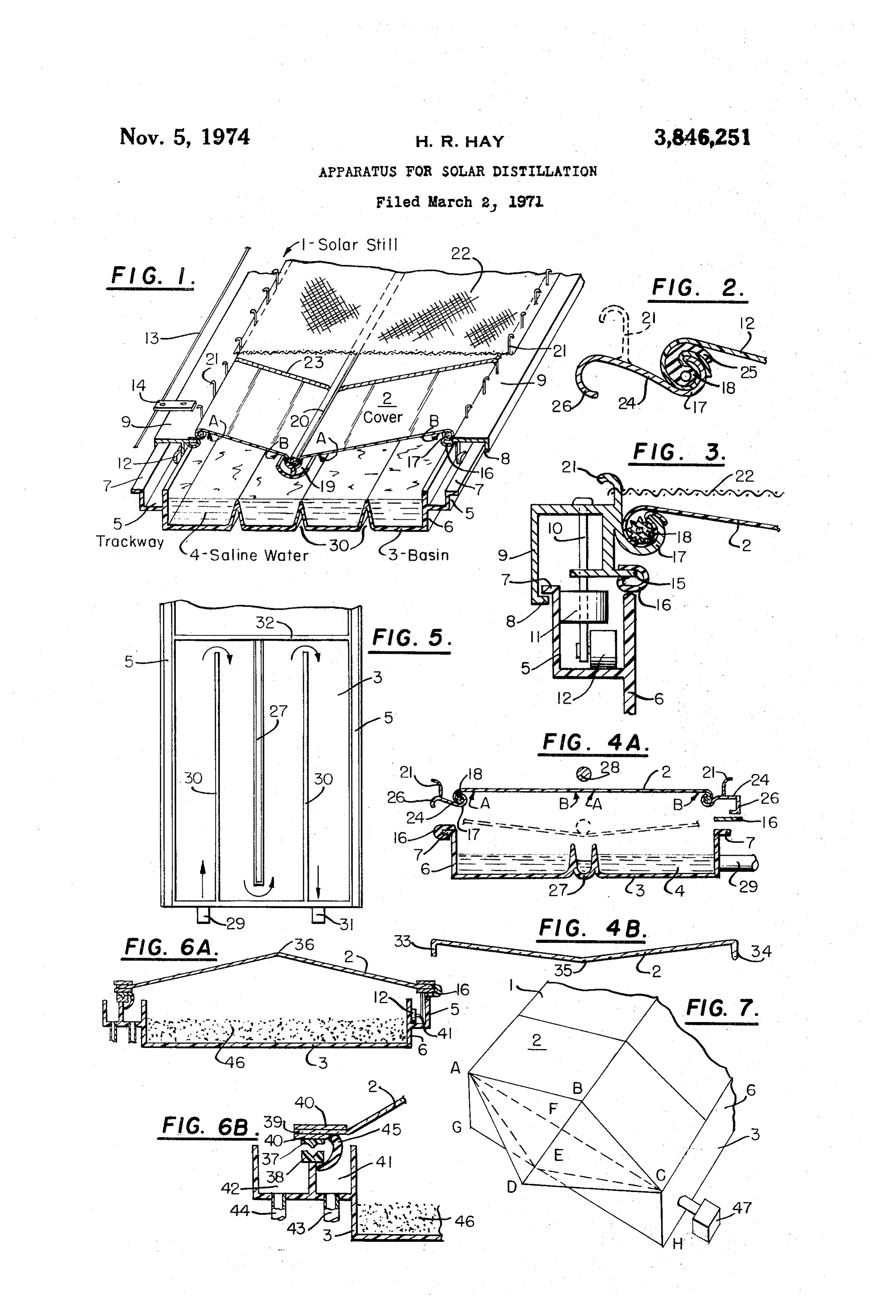
FIG. 4a is a cross section representation of the assem 3,846,251 bly of a solar still cover and means for fastening said APPARATUS FOR SOLAR DISTILLATION cover to a distilland basin; FIG. 4b is a cross section rep Harold R. Hay, Menlo Park, Calif. resentation of a glass cover suitably formed for mounting (2424 Wilshire Blvd., Los Angeles, Calif. 90057) in the distilland basin of FIG. 4a. Filed Mar. 2, 1971, Ser. No. 120,183 FIG. 5 is a top view representation of a distilland basin int, C. B01d 3/00 preformed with bottom corrugations which direct distil U.S. C. 202-234 15 Claims land flow and collect condensate. FIG. 6a is a cross section representation of a glass-cov
ABSTRACT OF THE DISCLOSURE O ered solar still with the cover made movable over a dis The solar distillation apparatus has a cover readily mov tilland basin formed integrally with a trackway and means able or removable from a first position for distilling, con for collecting distillate and rain; a granular material for densing, and collecting liquid to a second position expos recovery of water from atmosphere is shown in the dis ing the distilland basin and materials therein. Said ma tilland basin. FIG. 6b is an enlarged portion of FIG. 6a. terials may be liquids or solids, absorbent or non-absorb 15 of FIG.
7 is a fragmentary, top perspective representation solar still with alternative means for causing exter ent, for aiding in the process or recovery of water from the atmosphere while the cover is in its first or second nal air to displace air within the still. positions and in conjunction with natural or forced air The solar distillation art is now well known but of lim OWement. ited use owing to several shortcomings. Prior to the pres ent invention, distillation means lacked convenience and
This invention relates to means for moving and remov involved excessive expense to install the still cover and to ing a solar still cover to expose the distilland basin and remove it for purposes of cleaning or repairing still com materials contained therein to ambient air to facilitate ponents such as distilland basin or liner, insulation, evap maintenance of the solar still and to recover Water from orating surfaces such as wicks, distilland inlet and outlet, the atmosphere. The invention also relates to new struc 25 or condensate collecting troughs any of which may be components used in conjunction with other components tural forms for the cover and for the distilland basin and in the embodiments of this invention described and illus new means for fastening the cover to the distilland basin. trated in relation to horizontal stills but understood to be Moreover, it relates to a process in which the movement equally applicable and claimed equally for inclined stills. of natural or forced air over the distilland basin at night Moreover, glass covers have proved susceptible to break time results in the deposition of water subsequently recov 30 age during transport, erection and use; falling shards ered by solar distillation during the daytime. have damaged still liners. Fragility and weight of glass It is an object of this invention to provide novel means have dictated use of small panes requiring many vapor for quickly mounting and dismounting a Solar still cover, seals and making it difficult to uncover large areas for for moving said cover to facilitate maintenance of Solar access to the still basin. Plastic covers are also subject to still components, for exposing the distilland basin and ma wind and descending-object damage and may require terials therein with minimum effort and loss of produc patching. Out of service time for such maintenance should tivity, and for protecting said cover from damage. be minimized.
It is an added object to preform rigid or semi-rigid ma In prior art, distilland has been in the form of saline or terials into solar still components which serve a plural brackish ground water, damp ground or plant materials, ity of uses, reduce erection and maintenance time, and 40 or Water extracted from the air by absorbent materials increase yield. moved into the still for recovery of absorbed water. Solar It is a further object to recover water from the atmos still covers are used as rain collectors. Under adverse con phere by use of a solar still with a movable cover, or with a movable wall portion, thereby allowing natural flow of 45 ditions, all available sources of water must be utilized hence the still should be capable of combining many ways highly humid air to displace air of lower humidity, or by to collect and recover water.
causing such displacement by means forcing said highly For purposes of understanding better the disclosures humid air through a solar still. and claims, certain terms will be defined. Within the All or any portion of these objects may be accomplished in the embodiments of this invention. Other objects of the meaning of this invention, water is one of a class of liq present invention will become more apparent after read 50 luids to which the claims apply; alcohol and other liquids ing the following disclosure taken in conjunction with the vaporizable by Solar energy are within this class of liq drawings. It is understood that the drawings are for pur uids. A radiation-transmitting cover is understood to be pose of illustration only, and are not to be construed as one transparent, or translucent to solar rays and capable defining the limits of the invention, reference being made 55 of transmitting energy derived therefrom to convert dis to the appended claims for that purpose. tilland to vapors condensed on said cover in most embodi FIG. 1 is a fragmentary perspective and cross section ments disclosed but which may be condensed elsewhere representation of a solar still having a suspended conden as described in prior art. A distilland-retaining component sate collector and means for readily moving and remov is understood to be any material usually tending to retain ing the cover and means for protecting the cover. 60 distilland under the still cover during distillation; it may FIG. 2 is a fragmentary cross section representation of be: the still basin or liner; an evaporative wick; a bed of a means for quickly engaging and disengaging a solar still inert material such as sand; a hygroscopic inorganic ma cover; shown in dotted lines is an optional means for Se terial such as a salt or salt solution; a hygroscopic or curing a cover-protecting device over said cover.
FIG. 3 is a fragmentary cross section representation of 65 ganic material such as glycerine or plant materials; silica a means for moving a Solar still cover on a trackway. gel or similar sorptive materials; or it may be a combi
Page 3
nation of these and in any case preferably black or black moderately soft spline with an extension 25 easily bent to ened on the surface. provide a cushioning layer between cover 2 and either Also for clarification, a flexible cover is understood to cover fastener 17 or cover material held in cover fastener be a pliable film such as 4 mil polyvinylfluoride or other 17 as shown in FIG. 2. Spline 18 with extension 25 may plastic films suitable for the solar distillation art, whereas 5 be extruded in the comma-shape illustrated, but this is rigid covers include glass and methylmethacrylate or more difficult to insert in cover fastener 17 so I prefer other polymers usable as a substitute for glass. While having tension on cover 2 serve, at least in part, to bend usually the whole component to be described should be and form extension 25 of spline 18 into a cushioning formed or made operative in the manner described and layer.
so used in any part of the still where said component O Clamp 24 of FIG. 2 is a rigid cover-supporting member appears, in some cases it may be advantageous for the which may be hooked onto metal transport member ex improvement to be applied only in part to the compo tension 17 of FIG. 3 where spline 8 would then serve nent. Other terms will be made clear in the disclosure of as a sealing means. This alternative and indirect way of the various embodiments of this invention. fastening cover 2 to transport member 9 provides not In FIG. 1, the embodiment of my invention is a solar 5 only a movable cover but a removable one readily dis still with a flexible cover 2 mountcd over a liquid and engaged and replaced by a second cover with minimum vapor impermeable bottom 3 confining liquid distilland 4. effort and minimum interference with normal distillation A trackway 5, associated with sidewall 6 of basin 3, is in the Solar still. By means of dotted lines, it is indicated preferably an integral part of the sidewall but may be that rigid cover supporting member 24 may be provided separate and attached thereto by means not shown. As 20 with projections 21 as means for securing a screen (not better seen in FIG. 3 taken in conjunction with FIG. 1, shown) over cover 2 in the manner described in relation a projecting lip 7 on sidewall 6 overlies and engages a to FIGS. 1 and 3. The use of cover-supporting member projection 8 on elongated transport member 9 to check 24 will now be described in relation to another embodi vertical lift of said transport member to which is fastened ment of my invention.
shaft 10 on which are mounted a thrust-absorbing device 25 In FIG. 4a, a solar still is shown with various parts shown as wheel 11 and a transport means shown as wheel illustrated in assembly positions. Distilland basin 3 has 12 inside trackway 5 to facilitate moving transport mem sidewalls 6, projecting lips 7, and a centrally disposed ber 9. A cord 13, shown in FIG. 1 affixed to metal tab condensate collecting trough 27 which may be separate 14 fastened to transport member 9 provides one means from the bottom of said distilland basin but is shown for moving the transport member in the trackway. Trans 30 as a part thereof. Cover 2 is shown fastened between two port member 9 also has projection 15 shown fitted with rigid cover supporting members 24 of the type in FIG. 2 flexible sliding-seal 16 which contacts sidewall 6 to retard including the part 21 dotted therein. Cover 2 is held in vapor loss from inside still 1. the recess of extension 17 by spline 18. When cover 2 is The means for fastening flexible cover 2 to transport stretched taut between the two cover-supporting members, member 9, best shown in FIG. 3, consists of an elongated 35 open-end clamping extensions 26 fit over lips 7 on side extension 17 on said transport member and having a Wall 6 of basin 3 with just enough clearance for seal 16. recess in which cover 2 is held by suitable means such At the left of FIG. 4a, seal 16 is shown as preformed as compressible spline 18. FIG. 1 shows flexible cover 2 and fitted onto lip 7; to the right, seal 16 is shown as a sloping from the fastening means 17 and 18 toward the flat strip which will be forced into a shape comparable center of the still owing to the weight of the suspended 40 to the seal 16 at the left when the cover is in position. condensate collector 19 secured to the underside of cover After cover 2 has been lowered and clamps 26 engage 2 by spline 20 as described in my Pat. 3,314,862. Also basin lips 7, a weighting means, which may be a metal extending from transport member 9, as shown in both rod or pipe, is centered on the upper surface of cover 2. FIGS. 1 and 3, is projection 21 representing a means for This produces a downward force putting cover 2 in ten securing a screen 22 over cover 2 to prevent cover damage 45 sion and causing it to assume the form shown by dotted by stones, branches, or other descending objects. As lines. Cover tension draws clamping members 26 tight shown, screen 22, which may be of fiberglass or metal against compressing seals 16 on lips 7; this prevents vapor mesh, is hooked onto projections 21. leakage along the edges of the cover. Weighting means 28 As materials for the solar still embodiment of FIGS. may be secured centrally over condensate-collecting 1 and 3, I prefer basin 3 to be vacuum-formed from black, 50 trough 27 by cords (not shown) tied around said weight ABS plastic with sidewalls 6, trackway 5, and hold-down ing means and projections 21. If desired, a protecting lip 7 integrally a part thereof. Transport member 9, and Screen (not shown) may then be hooked onto projec its extensions and projections 8, 17, and 21, are best made tions 21.
from extruded aluminum with projections 21 shaped by FIG. 4a is shown with an inlet 29 for introducing transverse machining or sawing. Wheel shaft 10 is of 55 distilland 4 into the still. In operation, radiant energy suitable metal and wheels 11 and 12, as well as Seals 16 and splines 18 and 20, may be of butyl rubber, plastic, transmitted vapors through cover 2 vaporizes distilland 4 which condense on the underside of cover 2, preferably or metal. For cover 2, I prefer polyvinylfluoride; to re treated by well known means such as sandblasting to in duce wind flutter, I may apply strips of adhesive tape 23 crease Wettability, and condensate flows toward the low or glass fiber tape in a manner dividing the cover into 60 point of cover 2, under weighting means 28, from where smailer “panes,” thus dampening wind-caused cover flut it drips into condensate collecting trough 27 and is re ter. The tapes 23 also absorb extra weight of very heavy moved by conventional means not shown. The distillation rain or strong wind pressure. Other embodiments of my process of FIG. 1 is identical except that condensate invention may be made of the materials mentioned above collected in suspended collector 19 is removed through or as described later. 65
Another embodiment of my invention is illustrated in tubing (not shown) slipped over the suspended collector. FIG. 2 wherein flexible cover 2 is secured in an elongated When the cover 2 of FIG. 4a must be removed for cover fastening means 24 shown with a croSS Section access to distilland basin 3, weighting means 28 is lifted shape of an S though this may be varied as shown to off cover 2, cover-supporting members 26 are moved out the right of FIG. 4a. In FIG. 3, the spline 18 is shown 70 wardly and disengaged from lips 7 and the cover may be in a conventional shape which does not protect cover 2 taken away after disengaging similar or other means for from abrasion by the cover fastener 17 or by a portion of fastening the cover at the ends of the still. If the cover the cover material clamped by said spline. To prevent is removed for repair, a replacement can be quickly placed abrasion resulting from movement of cover 2 under wind over the distilland basin 3 with only a few minutes loss of action, and to absorb varying tensions, I prefer to use a 75 production.
Page 4
In FIG. 1, the bottom of basin 3 is shown formed with cover functions in the way and for the purposes described three corrugations 30 rising to approximately the surface for flexible cover 2 of FIG. 1, it being understood that a of distilland 4 and dividing the bottom of basin 3 into suitable condensate collector such as 27 of FIG. 4a is four portions or channels; either more or fewer dividing provided.
corrugations may be used. One purpose of corrugations In still another embodiment, glass cover 2 of FIG.4b, 30 is to add extra rigidity to basin 3 formed of semi or a glass cover of other shape adapted by appropriate rigid plastic, metal, or other materials and not uniformly means, is added over flexible cover 2 of FIG. 1 with a supported below. A second purpose for corrugations 30 is spacer, such as seal 16 shown to the right of FIG. 4a, to form end-around baffles to direct distilland flow through between the two covers at locations corresponding to a circuitous route between the inlet and outlet for distil 10 those overlying recesses of cover supporting members 17. land 4 in basin 3. By having the slope of the glass cover less than that of In FIG. 5, a top view of a distilland basin similar to that the flexible cover, a substantial air space is formed be of FIG. 1 shows distilland entering inlet 29 must follow tween the two covers to act, as indicated by prior art, in the course indicated by arrows in passage to outlet 31. a manner producing higher yields. Multiple covers have Stiffening corrugation 27 is in the form of a condensate hitherto been of the same material; in this embodiment collecting trough similar to that marked 27 in FIG. 4a they are of different materials and different form with and, like corrugations 30 directing distilland flow in an good purpose. The upper rigid cover absorbs wind pres end-around path. Baffling means such as the corrugations sures which would otherwise cause stress and flutter on a are important when flushing distilland through the still flexible cover resulting in shorter life and lower yields. basin 3 to remove concentrated distilland which might de 20 Thus protected, the flexible cover may be much thinner posit salts. It is generally advantageous to have distilland and less costly. The flexible cover should be provided inlet 29 and outlet 31 near one another for easy observa with a condensate-collecting trough such as indicated in tion of flow. End-around baffles are conventional for other FIGS. 1 or 4; the weighting means may be made very light hydraulic flow purposes but have not previously been since its purpose no longer includes stabilizing the flexible used in the manner disclosed here-particularly where a 25 cover against wind effects.
centrally disposed condensate collector forms one of the In another embodiment applying a glass cover over a baffles. flexible cover, the cover of FIG. 4b is made of two panes FIG. 5 also shows trackway 5 extending beyond still of glass joined by a flexible sealant at the location 35. end 32 in a manner permitting a cover mounted in the When this cover is of proper length and is placed over movable manner of the embodiment of FIG. 1 to be posi 30 flexible cover 2 of FIG. 4a with a spacer between the tioned over distilland basin 3 during a first period of distil covers above recesses in cover fastening means 17, the lation and permitting it to be moved to a second position weight of the glass is transferred to the flexible cover at a other than over a portion of distilland basin 3 during a point overlying the condensate collector 27 thus making second period when access to said portion is needed for unnecessary the use of an otherwise non-functional weight cleaning or other maintenance purposes. ing means such as metal rod 28. In this embodiment it Having described means for quickly moving and remov may not be possible to reduce the thickness of the flexible ing flexible solar still covers, I shall now disclose novel cover 2 as much as in the preceding embodiment but the means for accomplishing the same results with glass or flexible cover is substantially relieved of wind flutter. other rigid or semi-rigid covers. FIG. 4b represents a In the embodiment of this invention illustrated in FIG. readily removable glass cover 2 formed into a low-V shape 40 6a, a readily movable rigid cover 2, shown on the right with vertical projections 33 and 34 which need not neces side as mounted on wheels 12 moving in trackway 5 asso sarily be vertical nor shaped as shown for the embodi ciated with sidewall 6 of basin 3, drains condensate into ment to be described. Sheet glass may be cut to desirable the trackway which then serves as condensate collector sizes and formed in the shape shown by resting the cut 41. On the left of this figure and better shown in enlarge pieces on suitable molds, heating the glass to the soften 45 ment thereof in FIG. 6b, the rigid cover is shown mounted ing point, allowing gravity to form the pieces, and pass with a knife-edge 37 of plastic capable of moving in a ing the formed glass through an annealing and cooling runner 38 also shown as plastic but preferably of a dif means. The first advantage of the shaped glass is the ferent kind to reduce sliding friction as is well known in elimination of a seal along the centerline indicated as the the art. Glass cover 2 is shown as preformed with a low low-point 35. The cover 2 of FIG. 4b can also be placed 50 ridge requiring no sealant along ridge 36 and with hori directly onto a distilland basin such as 3 of FIG. 4a instead zontally extending flanges 39 held in a suitable clamping of the flexible cover shown associated therewith. Vapors means 40 which also holds sliding seal 16 and to which condensing on glass cover 2 of FIG. 4b then drip into one may be secured the wheel assembly 12 or the knife edge condensate-collecting trough 27 instead of requiring two member 37. Runner 38 is mounted on an appropriate part troughs as do glass covers of conventional types such as 55 of the condensate-collecting trough 41. An outlet 42 is the ridge or "greenhouse' types of FIGS. 6 and 7. shown for removing condensate from troughs 41. The weight of glass cover 2 of FiG. 4b causes a good As best seen in FIG. 6b, this embodiment may have vapor seal with soft seals of the type of 16 of FIG. 4a a rain-collecting trough 42 having a common wall with used in conjunction with the sidewalls of basin 3 thereof. collecting trough 41 and capable of receiving rain from As a precaution against wind lift, an adhesive, such as 60 cover 2 and having an outlet 44. The condensate and rain silicone or butyl rubber cement, may be used to hold the collecting troughs of this embodiment may be separate cover in place or suitable clamping means may be em from each other and from basin 3 but associated and ployed. This embodiment withstands downward thrust sometimes fastened together with adhesives or other fasten ing wind pressures such as have caused failures of glass ing means, to serve in the manner of my illustrated and covers sealed with silicone at ridges such as 36 of FIG. 6. 65 preferred integrated form.
The V cover also simplifies collection of rain drained to While the knife edge and runner assembly of FIG. 6b a single collection point rather than two as required for forms a vapor seal and also causes condensate to drain into cover 2 of FIG. 6. collector 41, irregular wear or particles of foreign matter In one embodiment of this invention, removable glass may diminish the effectiveness of this seal, hence a sepa cover 2 of FIG. 4b with projections 33 and 34 is sub 70 rate seal 45 is shown clamped by clamping device 40. stituted for flexible cover 2 of FIGS. 1 and 3 preferably The projection 34 on glass cover 2 of FIG. 4b is shown using splines 18 of the form shown in FIG. 2 as a sealing in the form of a knife edge which permits said cover to means. In this instance, it is preferred that the spline be move directly in a runner such as 38 of FIG. 6b. Glass preformed in the shape of a comma or serving in the same "knife edge” 34 should not be so sharp as to cut into manner. By means of this embodiment, a movable glass 75 runner 38. As the cases of FIGS. 1 and 4, provision can
Page 5
be made to assure that rigid cover 2 of FIGS. 4b and 6a when the cover has been returned to its first position. It cannot be lifted out of position by wind. In this embodi is to be understood that dew collection is not extraction of ment, it is evident that a portion 34 of the glass cover 2 has water from the air; it would occur on any non-absorbant become a transport member comparable to the transport surface having similar thermal properties and is the resuit member 9 of FIG. 1. Though not shown in FIGS. 6a and 5 of a temperature effect. The recovery of the dew by solar 6b, it is understood that cover-clamping member 40 may distillation is no more the drying of a material than the have an extension interlocking with the projecting shoulder distillation of a saline distilland. The collection and distil of trackway 38, or other means to prevent the cover from lation of dew is of particular advantage in arid regions of being lifted out of the trackway by high winds. high nighttime humidity but with scarce rain or ground Sealing means 16 and 24 of FIG. 4a, glass cover pro O) water sources-regions such as high altitude or coastal jections 33 and 34 of FIG. 4b, and transport means 12 and deserts. The same dew collection and recovery would 37 associated with the trackways 5 and 38 of FIGS. 6a result if distilland basin 3 contains a wicking material as and 6b are shown asymmetrical for purposes of illustrating an evaporative surface, or a layer of inert sand which may that the embodiments of this invention are not restricted be the second distilland-retaining component 46 of FIG. 6a. to specific shapes or means but may be varied or used in If the distilland basin 3 of FIGS. 1 or 4a retain through different combinations. Similarly, it is understood that the out the night some distilland from ground water source as interlocking engagement means for readily removing cover a second distilland-retaining component within the defini 2 from basin 3 of FIG. 4a may be applied along only one tion of this invention, dew will deposit on this distilland side or to a portion of one or more sides whereby it facili surface because it is cooled by radiation to the night sky tates access to the contents of the still basin. 20 several degrees below air temperature. If the distilland is A characteristic or the polyvinylfluoride cover is that the fairly concentrated brine, it may have a secondary mois original film is largely amorphous, but gradual aging, and ture-extracting effect as would residual salts left as the more particularly mechanical stresses, cause the plastic to second distilland-retaining component in a still from which become more crystalline whereupon it loses excellent all distilland was evaporated during the day. strength qualities. Three means have been described for 2 5 I do not claim the process of extracting water from the reducing damage resulting from wind flutter: a suspended air by means of hygroscopic materials such as glycerine or collector 19 of FIG. 1 or central weighting means 28 of cellulose; nor by inorganic materials such as silica gel. FIG. 4a reduce the cover span of flexible material; panel Nor do I claim the recovery of water from such materials ing strips 23 of FIG. 1 acts in the same way and carries by solar distillation because this, too, is a part of prior art. some of the cover load; and cushioning device 25 of FIG. 30 I do claim that the movable and removable cover em 2 absorbs stress and cover movement without causing bodiments of this invention causes these materials to be abrasion and crystallization. I shall now describe means used more efficiently. Moreover, I claim the process for for reducing strength loss caused by treatments required to increasing the efficiency of a solar distillation recovery of make the plastic cover more wettable. distilland obtained by dew collection through the use of For a permanent effect, wettability of plastic covers is a movable or removable cover. In this process, I expose best accomplished by chemical treatments or mechanical one or more distilland-retaining components to the night abrasion methods which generally increase crystallinity and sky for purposes of lowering their temperature below that weaken strength properties. Any unnecessary crystallinity which would be obtained if the cover were to remain over shortens the life of the cover, especially at points of cover 40 lying said components. Thus, I am allowing the deposi fastening. Therefore, I have found it desirable to limit the tion of dew to occur in a more convenient area for re wettability treatment to cover areas intermediate the covery by solar distillation.
cover-fastening or cover-supporting means and have found Whether air overlying the distilland-retaining com that this can be done without loss of condensate. ponent loses moisture by condensation or by absorption, As shown in FIG. 1, the wettability treatment is con its moisture content is lower than that more remote from fined to the cover portions between A and B; that is, be 45 said component. It is necessary, therefore, to displace the tween cover-supporting members 17 and the cover-fasten air of lower moisture concentration by air or higher mois ing portion of condensate collector 19. All cover material ture content to maximize yield. This I do by moving the contacting any of the rigid materials, splines, or other cover from a first position overlying one or more distill cover-fastening means should preferably be left untreated 50 land-retaining components to allow natural air flow, in though advantage will be had if even a portion of the the form of wind, to displace air of lower moisture content cover contacting such means is left untreated. Cover treat by air of higher moisture content. ment preferably begins a short distance from such cover In an embodiment of my invention, I may open one or fastening means; if this distance is not more than about more portions of the still other than the cover in a manner one-fourth inch, there will be little or no drop formation causing natural air flow to displace air underlying said of condensate near the cover-supporting means such as 55 cover and overlying a distilland-retaining component. The 17 of FIG. 1; drops formed near condensate collecting trough 19 drip into the underlying collecting troughs. The still is allowed to remain in this open condition several hours during the night-especially with the openings same result is obtained if, instead of the combined weight ing and condensate collector means 19 of FIG. 1, a 60 oriented to receive the prevailing winds. FIG. 7 shows this embodiment in part. The area bounded by letters weighting means 28 of FIG. 4a is used over the cover in ABCEA represents a portion of the end of the solar still combination with a separate condensate collector 27. In opened to receive natural air flow by movement of the this case, the weighting means 28 may be regarded as a material closing the still when in this first position to a cover-fastening means because it shapes and stabilizes second position indicated by the letters. ABCDA. The the cover.
As an added advantage of my readily movable and re 65 moved portion becomes a wind trap more effective if the movable cover, I have found that the solar still becomes material at D is at a higher elevation than B. The still an effective means for collecting moisture from the air. It should have a similar opening at the opposing end to is apparent from FIGS. 1 and 5 that moving the cover permit uninterrupted air flow; the fragmentary view in from a first position overlying a distilland-retaining con 70 FIG. 7 may represent either end of the same still. ponent, such as basin 3, to a position not overlying said If the still end ABCDA is made of rigid materials with basin doubles the area of dew collection. Dew collected two movable portions bounded by ABD hinged along line over the cover and drained into distilland basin 3, as well AB and BCD hinged along line BC, they would overlap as that collected in said basin, will be contaminated with in their lowered position and should preferably have a dirt. Thus, there is value in distilling it in the daytime 75 sealing means (not shown) to prevent daytime vapor loss.
Page 6
Means such as any conventional fastening device, possibly position exposing said portion to ambient overlying including a supporting means, could hold the movable por air and permitting the return of said member and tion in its second, nighttime position. If the raised portion said cover to said first position and ABCDA is a single piece of flexible material, such as a (c) means for removing from said solar still the liquid plastic film, it will take a folded form in the lowered first condensate so as to maintain in a relatively water position. Means for securing the film in its first and second free condition a direct downward bearing relationship positions are not shown but are well known in the art of between the rigid cover-supporting means and the folding or collapsible devises. It is also clear that the solar rigid trackway.
still end bounded by ABCHGA may have a sliding door 2. The apparatus of Claim 1 in which said transport bounded by ACHG, or a pair of doors AFEG and FCHE, O member is adapted to support a non-rigid cover. which may be the means for opening the end to permit 3. The apparatus of Claim 1 in which said transport displacement of air inside the still by air outside the still. member is adapted to support a rigid cover. Natural wind velocity, even augmented by a deflector, 4. The apparatus of Claim 1 in which said transport may not always be adequate to produce optimum flow of member is a portion of a glass cover. air for nighttime moisture collection. For more certain 55. The apparatus of Claim 1 in which means are pro movement of air, I may use an electric blower, or similar vided on said transport member for securing a cover air-forcing means 47, to cause air to flow under cover 2 protecting means which reduces damage from descending and over distilland basin 3 of the FIG. 7 still. The air may objects.
be forced into the still through the sidewall 6, through an 6. An apparatus for distillation of a liquid comprising end portion ABCHGA, or through cover 2. In prior art, a solar still having in combination a cover capable of air has been blown through a solar still during the daytime transmitting radiant energy to convert distilland in at period of distillation to cause vapors to be swept from the least one distilland-retaining component to vapor con still to a separate condensing means. At such a time, air densed to distillate and collected the improvements: (a) in outside the still has a lower moisture concentration than which an integrally formed portion of at least one side air within the still. Though this may be done with embodi 25 Wall of said distilland-retaining component is a rigid track ments of the present invention, I claim only the step of way supporting a movable cover on which said vapors are forcing the air through the still during nighttime when the condensed to a liquid, and (b) means for removing from outside air has a higher moisture content than air within said solar still the liquid condensate so as to maintain in the still. a relatively water-free condition a direct downward bear By causing natural or forced air to pass through a still 30 ing relationship between the movable cover and the rigid at night, when climatic conditions are favorable, the collec trackway.
tion of moisture may occur on all still components such 7. The apparatus of Claim 6 in which said trackway as the under side or cover 2, the sidewalls and ends, and forms at least a portion of a means for removing on one or more distilland-retaining components. Some condensate.
dew also collects on the outside of cover 2 and of other 8. The apparatus of Claim 6 in which said trackway portions of the still; provision can be made for collection forms at least a portion of a trough for the collection of of this dew in troughs also suited to collect rain. While interior moisture collection occurs without any special 9. An apparatus for the distillation of a liquid com absorbent material present, the movable and removable 40 prising a solar still having in combination one or more covers greatly facilitates both the displacement of air over distilland-retaining components, a cover capable of trans lying the distilland-retaining components and access to mitting radiant energy to convert distilland in said said components. distilland-retaining component to vapor which is con Although the embodiments of the invention illustrated densed to distillate which is collected, and the improve in FIGS. 1 through 7 have been described with considera ment which comprises:
ble particularity and other embodiments have also been 45 (a) a rigid cover-supporting transport member asso generally referred to, it is expressly understood that the ciated with said cover and adapted for moving said invention is not restricted thereto, as the essence of the cover, and disclosed invention is capable of receiving a variety of (b) a rigid trackway associated with a distilland expressions which will readily suggest themselves to those retaining component said trackway directly support skilled in the art. Obviously, changes may be made in the 50 ing and interlocking said transport member in a arrangement, proportion, and composition of certain parts manner which permits said member to be moved and certain features may be used with other features with from a first position in which said cover overlies at out departing from the spirit of this invention. I do not least a portion of said distilland-retaining component wish, therefore, to be limited to the precise details of construction and operation set forth but desire to avail 55 to a second position exposing said portion to ambient myself of all aspects within the scope of the appended overlying air and permitting the return of said mem claims. ber and said cover to said first position, and What is claimed is: (c) means for removing from said solar still the liquid 1. An apparatus for the distillation of a liquid com condensate so as to maintain in a relatively water prising a solar still having in combination one or more 60 free condition a direct downward bearing relationship distilland-retaining components, a cover capable of trans between the rigid cover-supporting transport member mitting radiant energy to convert distilland in said and the rigid trackway. distilland-retaining component to vapor which is condensed 10. The apparatus of Claim 1 in which said transport to distilland which is collected, and the improvement 65 member is adapted to support a rigid cover. which comprises: 11. The apparatus of Claim 1 in which said transport (a) a rigid cover-supporting transport member which member is a portion of a glass cover.
at least in part is adapted for moving said cover as 12. The apparatus of Claim 1 in which said transport a whole, and member is adapted to support a non-rigid cover. al (b) at least one rigid trackway associated with a 70 13. The apparatus of Claim 1 in which said transport distilland-retaining component said trackway en member is moved by means which include a rolling gaging said transport member in a manner which member.
permits said member to be moved from a first posi 14. The apparatus of Claim 1 in which said transport tion in which said cover overlies at least a portion member is moved by means which include a sliding of said distilland-retaining component to a second 75 member.
Page 7
15. The apparatus of Claim 1 in which means are 956,771 5/1910 Kline ----------------- 47-17 provided on said transport member for securing a cover- 549,656 11/1895 Pickering ------------- 47-17 protecting mesh which reduces damage from descending 3,004,543 10/1961 Pinet --------------- 47-17 X objects. 2,601,326 6/1952 Rohs et al. ---------- 47-31 X
References Cited 5 FOREIGN PATENTS
UNITED STATES PATENTS 741, 79 11/1955 Great Britai 47
332; 3. Birdo r a n w had es as a moa - - -26. NORMANYUDKOFF, Primary Examiner
3,351,538 11/1967 Andrassy ---------- 203-10 X D. EDWARDS, Assistant Examiner 2,614,366 10/1952 Fleklin ------------- 47-17 X 203-10, Dig. 1, 100
Provenance
- Collection
- Cited prior art
- Original PDF
- patentimages.storage.googleapis.com →
- Filed
- 1971-03-02
- Pages
- 7
- Method
- pdftotext (the PDF's own text layer) + pdftoppm 300dpi page scans
- Source
- Google Patents bibliographic record
- Granted
- 1974-11-05
- Inventors
- H Hay
- Transcribed from
- patentimages.storage.googleapis.com →