patent · US3784096
Hydrogen heating system
8 January 1974
Page 1 — bibliographic record
United States Patent (19) 11 3,784,096 Zweifel (45) Jan. 8, 1974 54 HYDROGEN HEATING SYSTEM 1,853,431 4/1932 Johnson.................................. 236/9 75) Inventor: Fritz Zweifel, Linthal, Switzerland 3,497,312 2/1970 Zeff et al............................ 204/129 3,485,742 12/1969 Emich et al......................... 204/230 (73) Assignee: The Raymond Lee Organization,
Inc., New York, N.Y.; a part Primary Examiner-William E. Wayner interest
Attorney-Howard I. Podell
21 Appl. No.: 271,178 57 ABSTRACT 52 U.S. Cl.................. 237/1 R, 204/129, 204/230, A gas furnace heating system, utilizing as a fuel, hy 431/171 drogen gas obtained from the electrolytic decomposi (51) Int. Cl........................ C01b 13/04, F24d 12/00 tion of water. Water is fed from a storage tank into an (58) Field of Search............................ 204/230, 129; electrolytic decomposition cell, with the hydrogen gas 237/12, 1 R, 81, 2 R; 431/171 fed through appropriate piping and valves to the burner. The burner is controlled by a thermostat in 56 References Cited the heated area. The oxygen produced may be vented UNITED STATES PATENTS into the atmosphere.
558, 176 4/1896 Huber................................. 431/171 1 Claim, 1 Drawing Figure
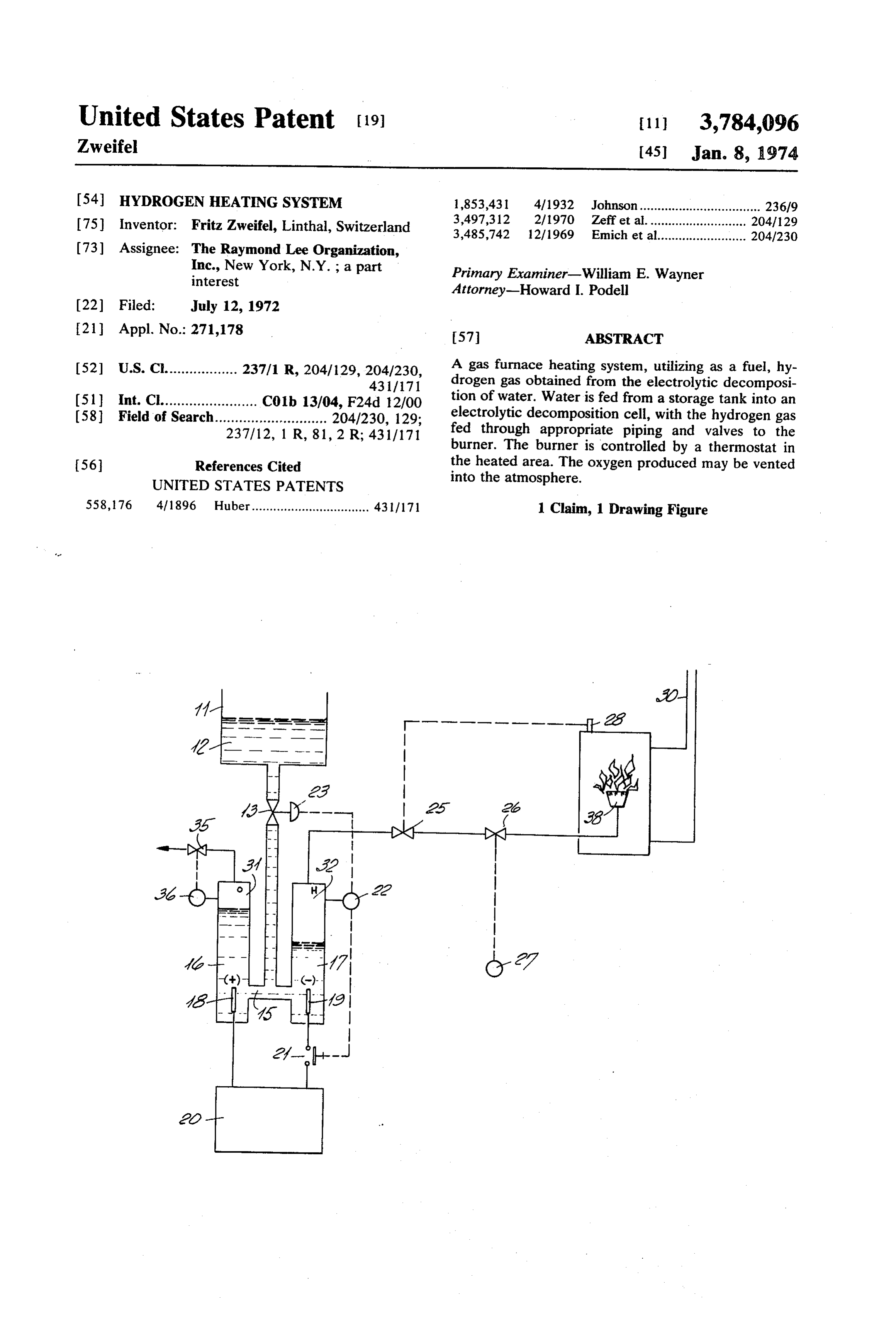
Page 2
Drawing sheet — no readable text.
Page 3
HYDROGEN HEATING SYSTEM temperature in the space which is served by the heating SUMMARY OF THE INVENTION system 30 of the burner 38.
The flow of electricty to the electrolytic cell 15 is
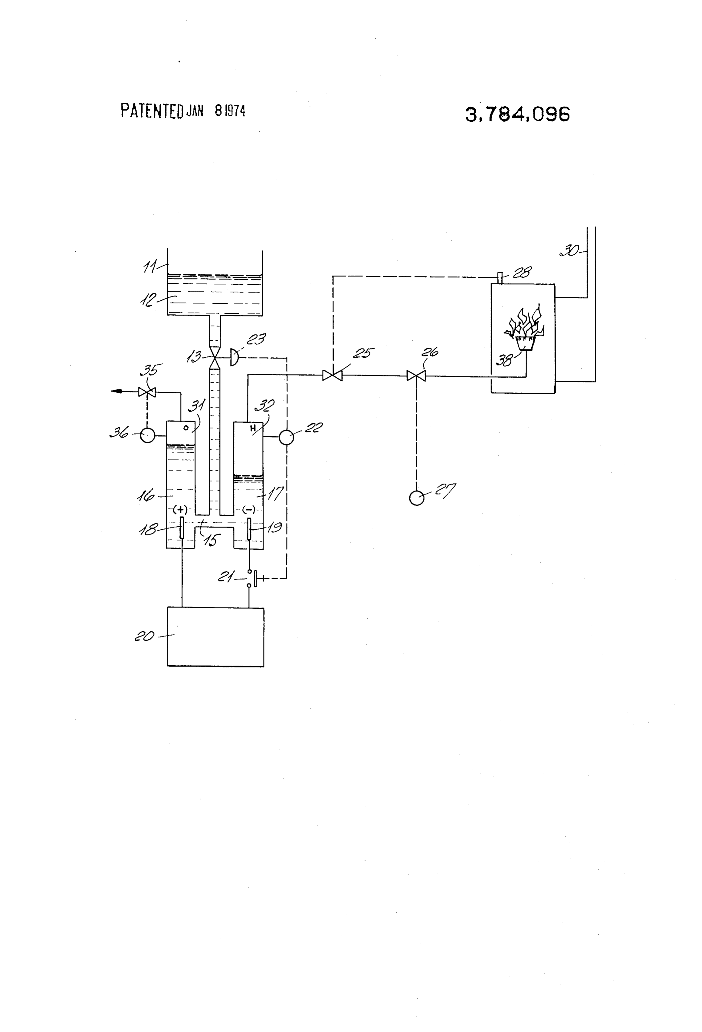
This invention relates to a gas fueled heating system, controlled by automatic switch 21 which is regulated and particularly to a gas heating furnace which is fueled by a pressure sensor 22. Sensor 22 is responsive to the by hydrogen, with the hydrogen produced by electro pressure of hydrogen gas 32 produced in the leg 17 of lytic decomposition of water. the electrolytic cell 15. Pressure sensor 22 also controls An advantage of this invention is the use of a gas fuel solenoid 23 which operates the valve 3 which admits in the heating burner which results in the complete ab water 12 from storage tank 11 into the electrolytic cell sence of pollutant gases. 10 15.
The hydrogen gas, which serves as fuel, is formed in In operation, a call for heat by room thermostat 27 a water-fed electrolytic cell by the passage of 1200 Am opens valve 26 to permit hydrogen gas to flow to the peres of electric current under a potential of 2 Volts. burner 38 and causing a reduction of hydrogen gas The water is continuously fed into the cell in response pressure in leg 17 of the electrolytic cell 15. Pressure to automatic valves dependent upon the water level 5 sensor 22 simultaneously causes valve 13 to open by and gas pressure in the cell. Electrolysis of the water produces gas in the proportion of two parts of oxygen activating solenoid 23, and water 12 is admitted into the electrolytic cell 15. The electrical circuit of the to one part of hydrogen by volume. An exhaust valve power supply 20 is activated by closing switch 21, in the electrolytic cell vents the produced oxygen to the which results in the diassassociation of the water 12 atmosphere. The hydrogen is fed to a gas burner, the 20 into hydrogen gas 32 and oxygen gas 31. If the pressure operation of which is controlled by a thermostat lo of hydrogen gas 32 increases in the system to an exces cated in the area which is heated by the burner. sive amount, the sequence is reversed and the electro BRIEF DESCRIPTION OF THE DRAWING lytic action and supply of water to the cell 15 is auto matically stopped.
The objects and features of the invention may be un 25 Since obvious changes may be made in the specific derstood with reference to the following detailed de embodiment of the invention described herein, it is in scription of an illustrative embodiment of the inven dicated that all matter contained herein is intended as tion, taken together with the accompanying drawing illustrative and not as limiting in scope. which is a schematic diagram of the flow of the water Having thus described my invention, what I claim as into the electrolytic cell, and of the flow of the gases new and desire to secure by Letters Patent of the produced in said cell to the heating burner. United States is:
DESCRIPTION OF THE PREFERRED 1. A heating system which is fueled by hydrogen gas EMBODIMENT: produced by the electrolytic decomposition of water, Turning now descriptively to the drawing, in which 35 said system including an electrolytic cell in which water is decomposed into hydrogen gas and oxygen gas in similar reference characters denote similar elements throughout the view, the illustration indicates water 12 separate compartments housing the cathode and the stored in tank 11 fed by gravity into electroytic cell 15. anode respectively, with automatic pressure-sensitive Cell 15 is divided into two vertical legs 16 and 17, and controlled valve means to exhaust the produced oxygen is supplied with direct current electricity by power unit 40 gas to the atmosphere, and thermostat-controlled valve 20. Power unit 20 may be a direct current generator, means to control the flow of the produced hydrogen battery, or alternating current rectifier operating from gas to a burner, said thermostat-controlled valve means an alternating current supply line. Power unit 20, pref being responsive to the ambient temperature in the erably, supplies 1200 amperes at 2 volt potential direct area which is heated by the heating system, in which a current to the anode 18 and cathode 19 of the electro 45 pressure sensor in the hydrogen-producing compart lytic cell 15. ment of the electrolytic cell controls a valve which reg Oxygen is formed in cell leg 16 which surrounds the ulates the admission of water into the electrolytic cell, the anode 18. Excessive pressure of oxygen gas 31 in and in which the pressure sensor in the hydrogen pro leg 16 of the cell 15 is relieved by venting to the atmo ducing compartment of the electrolytic cell also con sphere. Exhaust valve 35 is controlled by pressure regu 50 trols an electrical switch which controls the flow of lator 36 which is responsive to the pressure of oxygen electricity to the electrolytic cell, so that a reduction of gas 31 in leg 16 of the electrolytic cell 15. gas pressure in the hydrogen-producing compartment Hydrogen gas 32 is formed in leg 17 of the electro of the electrolytic cell results in the automatic switch lytic cell 15 and is led to the gas burner 38 through con ing on of the electrical current that produces the elec trol valves 25 and 26. Control valve 25 is activated by 55 trolysis and in the automatic opening of the valve which a thermostat 28 in the furnace flue which shuts off the causes water to flow into the electrolytic cell, where flow of hydrogen gas to the burner 38 when the flame said reduction of hydrogen gas pressure in the elec temperature becomes too high, or when the flame has trolytic cell is caused by the operation of the said gone out in the burner 38. Control valve 26 is activated thermostat-controlled valve means that controls by the room thermostat 27 and regulates the flow of hy 60 the flow of the hydrogen gas to the burner. drogen gas to the burner 38 so as to maintain desired : *k s:
Provenance
- Collection
- Cited prior art
- Original PDF
- patentimages.storage.googleapis.com →
- Filed
- 1972-07-12
- Pages
- 3
- Method
- pdftotext (the PDF's own text layer) + pdftoppm 300dpi page scans
- Source
- Google Patents bibliographic record
- Granted
- 1974-01-08
- Inventors
- F Zweifel; Lee Raymond Organization Inc
- Transcribed from
- patentimages.storage.googleapis.com →