patent · US4332775
Hydrogen generator utilizing solar energy to dissociate water
1 June 1982
Page 1 — bibliographic record
United States Patent (19) 11) 4,332,775 Genequand et al. 45) Jun. 1, 1982 54 HYDROGEN GENERATOR. UTILIZING 4,233,127 11/1980 Monahan ........................ 422/186 X SOLAR ENERGY TO DESSOCATE WATER OTHER PUBLICATIONS 75 Inventors: Pierre Genequand, Moillebeau-Parc; Fletcher, E. A. et al.; "Hydrogen and Oxygen from Daniel M. Gross, Carouge, both of Water”; Science, vol. 197, 9/77, pp. 1050-1056. Switzerland Nakamura T.; "Hydrogen Production from Water Uti 73) Assignee: Battelle Memorial Institute, lizing Solar Heat at High Temperatures', Solar Energy; Columbus, Ohio vol. 19, pp. 467-475.
(21) Appl. No.: 200,618 Primary Examiner-Barry Richman Attorney, Agent, or Firm-Philip M. Dunson
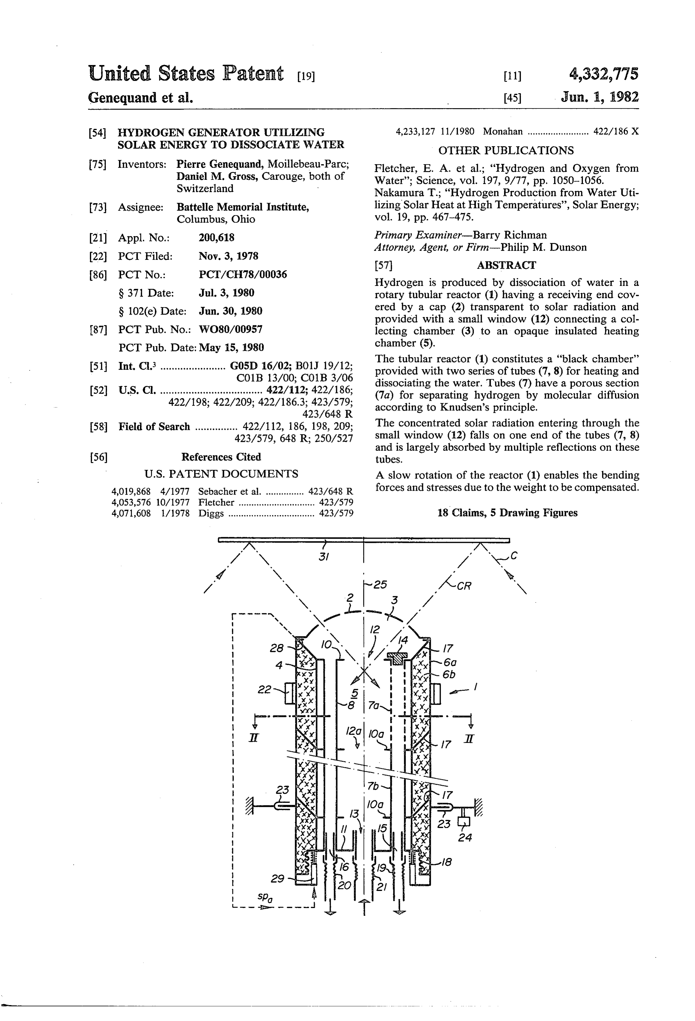
Hydrogen is produced by dissociation of water in a
S 371 Date: Jul. 3, 1980 rotary tubular reactor (1) having a receiving end cov S 102(e) Date: Jun. 30, 1980 ered by a cap (2) transparent to solar radiation and provided with a small window (12) connecting a col 87) PCT Pub. No.: WO80/00957 lecting chamber (3) to an opaque insulated heating PCT Pub. Date: May 15, 1980 chamber (5).
51 Int. Cl. ....................... G05D 16/02; B01J 19/12; The tubular reactor (1) constitutes a "black chamber' CO1B 13/00; C01B3/06 provided with two series of tubes (7,8) for heating and dissociating the water. Tubes (7) have a porous section (52) U.S. Cl. .................................... 422/112; 422/186; (7a) for separating hydrogen by molecular diffusion 422/198; 422/209; 422/186.3; 423/579; according to Knudsen's principle.
58 Field of Search ............... 422/112, 186, 198, 209; The concentrated solar radiation entering through the 423/579, 648 R; 250/527 small window (12) falls on one end of the tubes (7,8) and is largely absorbed by multiple reflections on these 56) References Cited tubes.
4,019,868 4/1977 Sebacher et al. ............... 423/648 R forces and stresses due to the weight to be compensated. 4,053,576. 10/1977 Fletcher .............................. 423/579 4,071,608 l/1978 Diggs .................................. 423/579 18 Claims, 5 Drawing Figures
Page 2
Drawing sheet — no readable text.
Page 3
Drawing sheet — no readable text.
Page 4
Drawing sheet — no readable text.
Page 5
thermal and mechanical constraints to which the heated
HYDROGEN GENERATOR. UTILIZING SOLAR refractory materials are subjected to be reduced. ENERGY TO DISSOCATE WATER However, the mass flux of a gas diffusing across a porous wall increases as a function of the pressure dif
TECHNICAL FIELD ference across this membrane, with the result that the The present invention relates to the production of operation of the generator at very low pressures re hydrogen using solar energy to dissociate water. duces the flow rate of the gas that is consequently sepa PRIOR ART rated. It is nevertheless possible to take account of this
reduction during separation by molecular diffusion, as
It has already been proposed to dissociate directly will be seen hereinafter.
water flowing over a surface heated by concentrated In addition, in order to ensure a good collection effi solar radiation, and collect the hydrogen and oxygen. ciency of the concentrated solar radiation, of the order The state of the art in this field may be illustrated by of 80% for example, the surface absorbing this concen the following publications: trated radiation should not re-emit an excessive amount (1) The article by E. A. Fletcher, entitled: “Hydro 15 of the absorbed energy, i.e. it should re-emit at most gen and Oxygen from Water', and published in the 20% for such a collection efficiency of 80%. review “Science', Vol. 197, Sept. 9, 1977, pages Nevertheless, the radiation flux re-emitted by a wall 1050-1056. heated to 2500' K. is of the order of 200 W/cm2. Conse (2) U.S. Pat. No. 4,053,576 to E. A. Fletcher. 20 quently, a collection efficiency of 80% would only be
(4) The article by T. Nakamura entitled: "Hydrogen achieved if the incident concentrated radiation flux Inc Production from Water utilising Solar Heat at high were equal to 1000 W/cm2, which corresponds to a Temperatures' and published in the review "Solar En concentration 10,000 times greater than that of the solar ergy', Vol. 19, pages 467-475, by Pergamon Press in radiation.
1977. 25 Consequently, assuming that the solar concentrator (5) Belgian Pat. No. 845,009 to the C.G.E. intercepts the solar radiation over a surface area of 50 The article by E. A. Fletcher mentioned in (1) above m, and concentrates the radiation 10,000 times to pro describes more particularly the following: vide a collection efficiency of 80% as mentioned above, Direct concentration of solar radiation onto a molec the surface illuminated by this concentrated radiation ular diffusion porous membrane (operating under 30 should not exceed 50 cm2. This clearly imposes a limit Knudsen flow conditions). on the collecting surface that could be heated directly Dissociation of water by passage through the mem by the concentrated solar radiation, while at the same brane thus heated directly by the concentrated solar time ensuring a good collection efficiency of the inci radiation. dent radiation.
Partial separation of hydrogen and oxygen by selec 35 Moreover, the heated collecting surface should be tive molecular diffusion in this membrane. have as far as possible like a black body so as to be able Compression of the vapours enriched in H2 and O2 to absorb the maximum amount of the incident concen respectively, after having cooled the vapours to a low temperature, and separation by H2O by condensation so trated radiation and thereby ensure a good collection efficiency.
as to recover H2 and O2 under pressure. 40
As regards the separation rate of the gases obtained
Preheating of the water to be dissociated, by counter from current heat exchange with the vapours enriched in H2 when the dissociation of water, this generally decreases the separation takes place at reduced pressure, as and O2 and superheated by passage through the said has already been mentioned above, which is scarcely membrane.
Use of a refractory porous membrane formed from 45 compatible with the requirement of having a reduced ThO2. collecting surface mentioned in connection with the collection efficiency.
OUTLINE OF THE INVENTION The separation of the gases by diffusion under Knud The main advantage of using concentrated solar radi sen flow conditions through a porous wall has a particu ation to effect the direct dissociation of water is that in 50 lar advantage in this connection however, since it pro principle it enables high thermodynamic yields at high vides the possibility of compensating a reduction in the temperature to be obtained. pressure by an increase in the diameter of the pores This advantage is however restricted by the refrac involved in the diffusion. A high mass flow may thus be tory construction materials at present available. In fact, guaranteed during the separation, even if the latter takes at the present time there are no refractory materials 55 place at very low pressures.
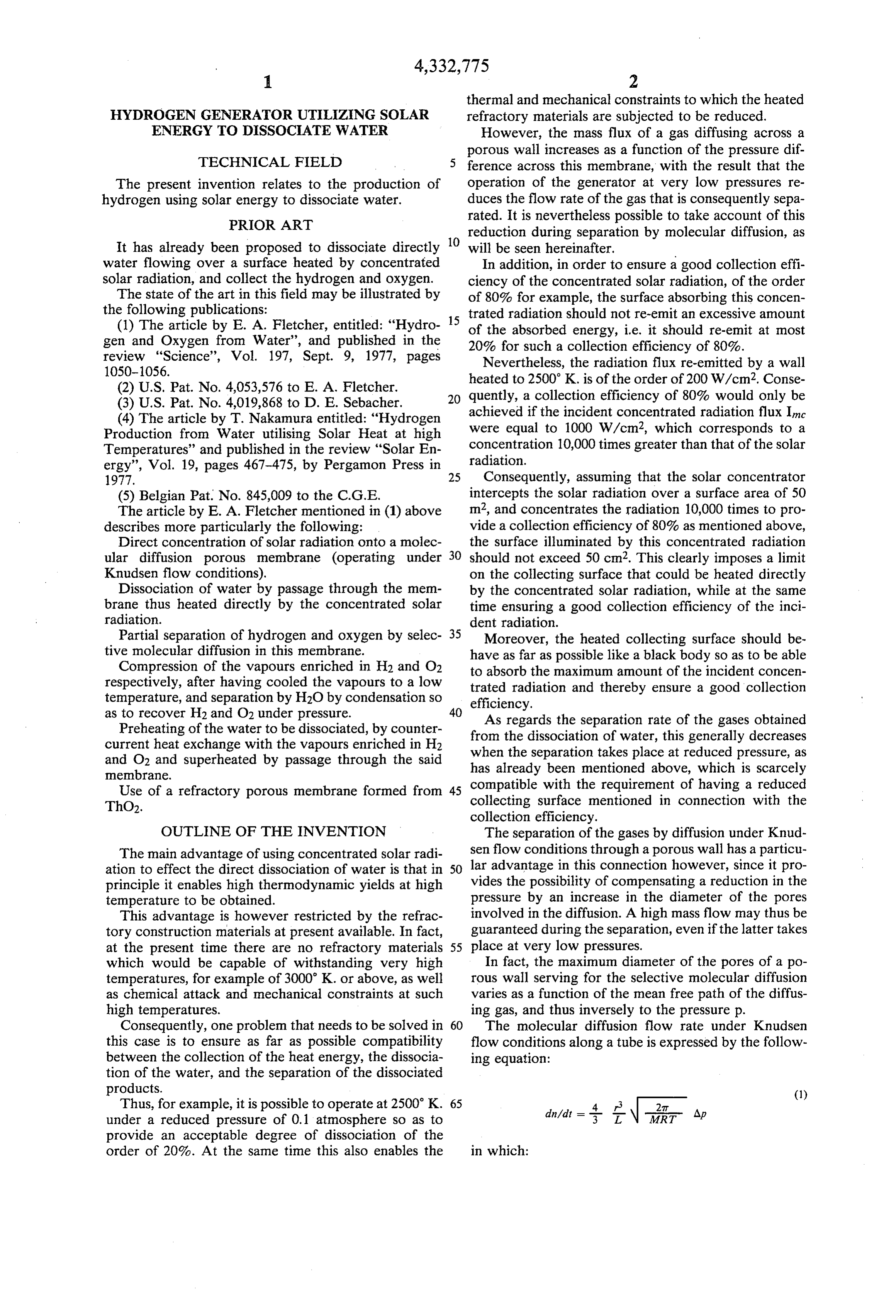
which would be capable of withstanding very high In fact, the maximum diameter of the pores of a po temperatures, for example of 3000 K. or above, as well rous wall serving for the selective molecular diffusion as chemical attack and mechanical constraints at such varies as a function of the mean free path of the diffus high temperatures. ing gas, and thus inversely to the pressure p. Consequently, one problem that needs to be solved in 60 The molecular diffusion flow rate under Knudsen this case is to ensure as far as possible compatibility flow conditions along a tube is expressed by the follow between the collection of the heat energy, the dissocia ing equation:
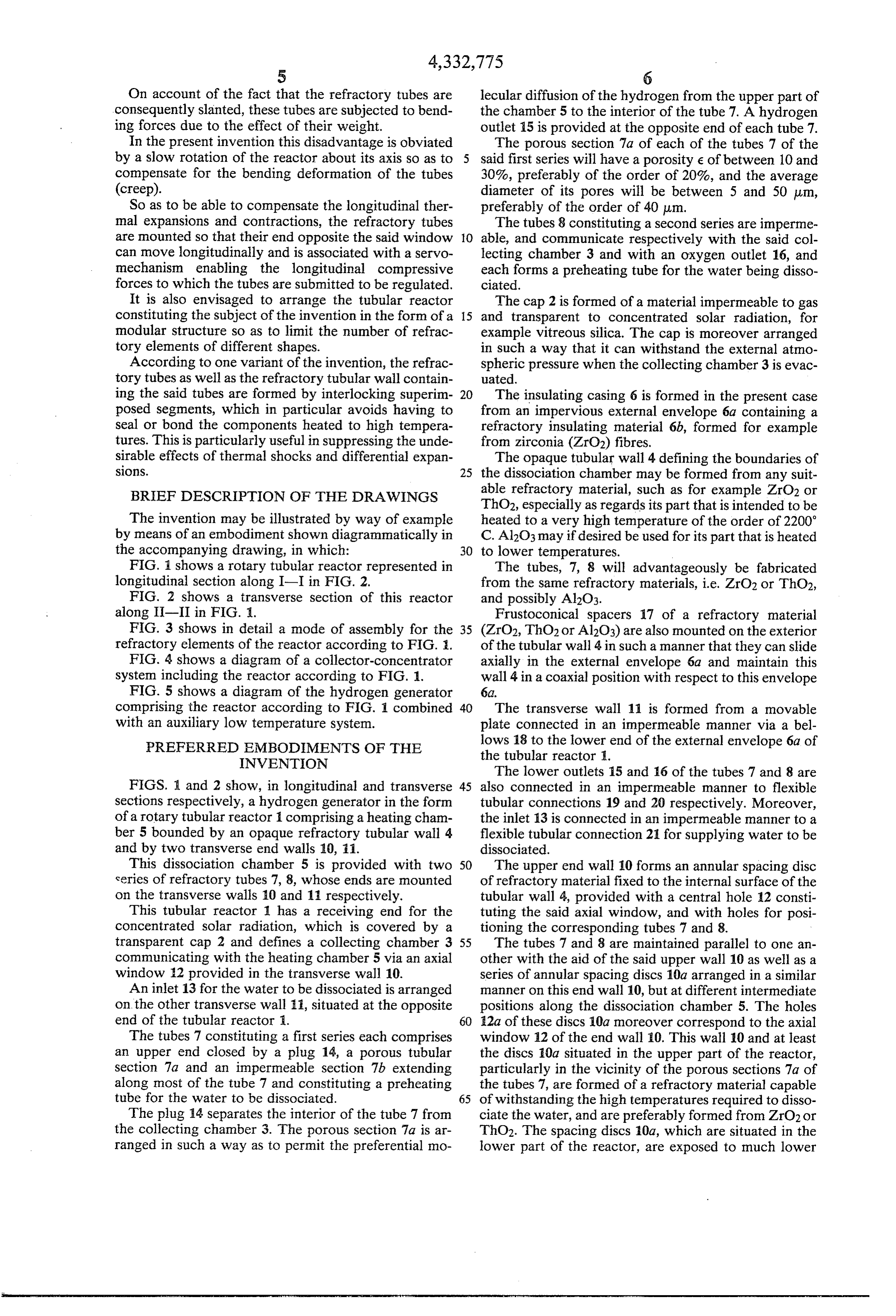
tion of the water, and the separation of the dissociated products. (1) Thus, for example, it is possible to operate at 2500 K. 65 2T Ap under a reduced pressure of 0.1 atmosphere so as to provide an acceptable degree of dissociation of the order of 20%. At the same time this also enables the in which:
Page 6
dn/dt is the diffusion flow rate expressed in moles/- These conditions would moreover be able to consti Sec; tute conditions moderately well adapted to the require r is the radius and L is the length of the tube; ments of a satisfactory operation of the generator. Ap is the pressure difference; The hydrogen generators proposed hitherto are sub M is the molecular weight of the diffusing gas; and 5 ject in addition to a further problem which is due to the R is the universal gas constant. fact that the wall onto which the solar radiation is di Now, if a uniformly porous wall is compared to a rectly concentrated does not at all have the properties uniform arrangement of juxtaposed tubes whose radius of a black body.
r is equal to the average radius of the pores and whose O In fact, the refractory materials proposed for the length L corresponds to the thickness of this wall, the construction of the collecting surface, such as thorium molecular diffusion flow rate across this wall may be dioxide, have a high reflecting power even at 2500 K. given approximately by the following equation derived The design and construction of an industrial hydro from equation (1) above: gen generator thus poses technical and economic prob 15 lens which are all the more complex since the collec
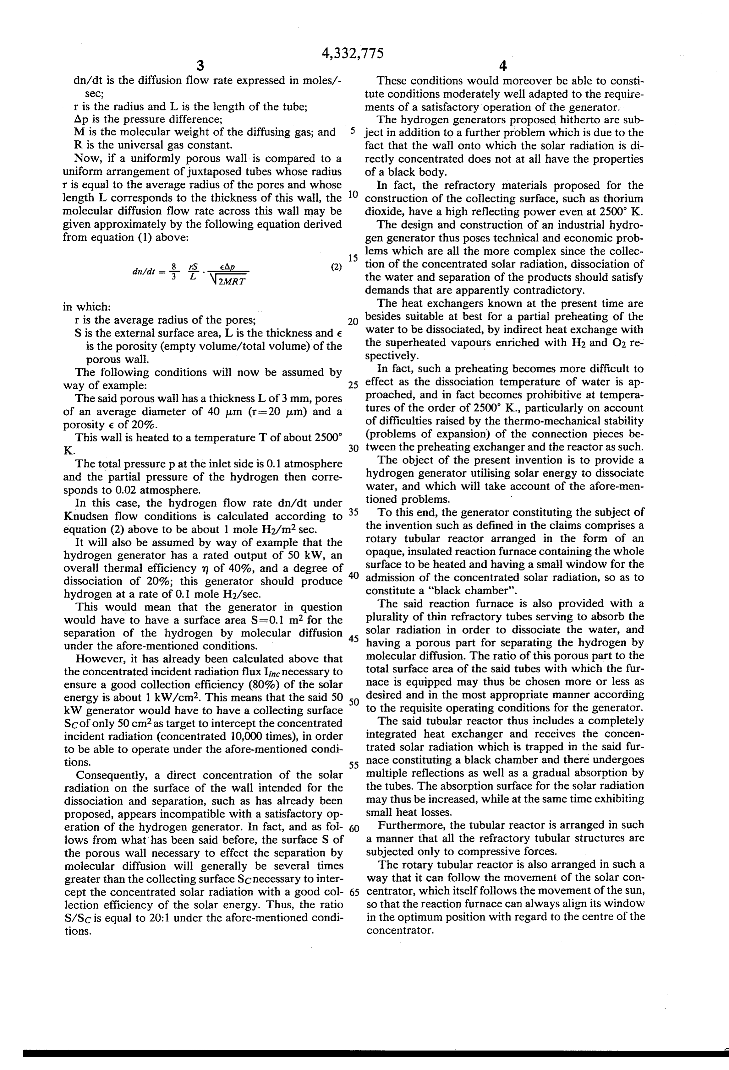
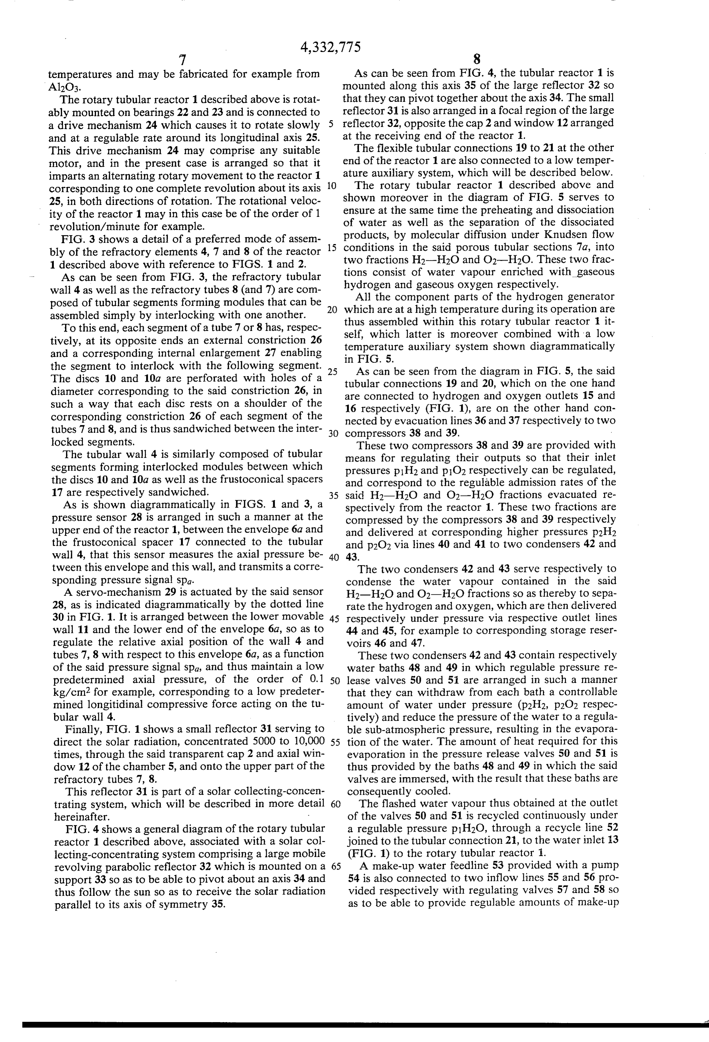
din Adit is -- eAp (2) tion of the concentrated solar radiation, dissociation of 3 L \rr the water and separation of the products should satisfy demands that are apparently contradictory.
in which: The heat exchangers known at the present time are r is the average radius of the pores; besides suitable at best for a partial preheating of the S is the external surface area, L is the thickness and e water to be dissociated, by indirect heat exchange with is the porosity (empty volume/total volume) of the the superheated vapours enriched with H2 and O2 re spectively.
porous wall.
The following conditions will now be assumed by In fact, such a preheating becomes more difficult to way of example: 25 effect as the dissociation temperature of water is ap The said porous wall has a thickness L of 3 mm, pores proached, and in fact becomes prohibitive at tempera of an average diameter of 40 um (r=20 um) and a tures of the order of 2500 K., particularly on account porosity e of 20%. of difficulties raised by the thermo-mechanical stability This wall is heated to a temperature T of about 2500 (problems of expansion) of the connection pieces be K. tween the preheating exchanger and the reactor as such. The total pressure p at the inlet side is 0.1 atmosphere The object of the present invention is to provide a and the partial pressure of the hydrogen then corre hydrogen generator utilising solar energy to dissociate sponds to 0.02 atmosphere. water, and which will take account of the afore-men In this case, the hydrogen flow rate din/dt under tioned problems.
Knudsen flow conditions is calculated according to 35 To this end, the generator constituting the subject of equation (2) above to be about 1 mole H2/m2 sec. the invention such as defined in the claims comprises a It will also be assumed by way of example that the rotary tubular reactor arranged in the form of an hydrogen generator has a rated output of 50 kW, an opaque, insulated reaction furnace containing the whole overall thermal efficiency m of 40%, and a degree of 40 surface to be heated and having a small window for the dissociation of 20%; this generator should produce constitute admission of the concentrated solar radiation, so as to hydrogen at a rate of 0.1 mole H2/sec. a "black chamber'. This would mean that the generator in question The said reaction furnace is also provided with a would have to have a surface area S=0.1 m2 for the plurality of thin refractory tubes serving to absorb the separation of the hydrogen by molecular diffusion 45 solar radiation in order to dissociate the water, and under the afore-mentioned conditions. having a porous part for separating the hydrogen by However, it has already been calculated above that molecular diffusion. The ratio of this porous part to the the concentrated incident radiation flux Inc necessary to total surface area of the said tubes with which the fur ensure a good collection efficiency (80%) of the solar nace is equipped may thus be chosen more or less as energy is about 1 kW/cm2. This means that the said 50 50 desired and in the most appropriate manner according kW generator would have to have a collecting surface to the requisite operating conditions for the generator. Scof only 50 cm2 as target to intercept the concentrated The said tubular reactor thus includes a completely incident radiation (concentrated 10,000 times), in order integrated heat exchanger and receives the concen to be able to operate under the afore-mentioned condi trated solar radiation which is trapped in the said fur tions. 55 nace constituting a black chamber and there undergoes Consequently, a direct concentration of the solar multiple reflections as well as a gradual absorption by radiation on the surface of the wall intended for the the tubes. The absorption surface for the solar radiation dissociation and separation, such as has already been may thus be increased, while at the same time exhibiting proposed, appears incompatible with a satisfactory op small heat losses.
eration of the hydrogen generator. In fact, and as fol 60 Furthermore, the tubular reactor is arranged in such lows from what has been said before, the surface S of a manner that all the refractory tubular structures are the porous wall necessary to effect the separation by subjected only to compressive forces. molecular diffusion will generally be several times The rotary tubular reactor is also arranged in such a greater than the collecting surface Scnecessary to inter way that it can follow the movement of the solar con cept the concentrated solar radiation with a good col 65 centrator, which itself follows the movement of the sun, lection efficiency of the solar energy. Thus, the ratio so that the reaction furnace can always align its window S/SC is equal to 20:1 under the afore-mentioned condi in the optimum position with regard to the centre of the tions. Concentrator.
Page 7
On account of the fact that the refractory tubes are lecular diffusion of the hydrogen from the upper part of consequently slanted, these tubes are subjected to bend the chamber 5 to the interior of the tube 7. A hydrogen ing forces due to the effect of their weight. outlet 15 is provided at the opposite end of each tube 7. In the present invention this disadvantage is obviated The porous section 7a of each of the tubes 7 of the by a slow rotation of the reactor about its axis so as to said first series will have a porosity e of between 10 and compensate for the bending deformation of the tubes 30%, preferably of the order of 20%, and the average (creep). diameter of its pores will be between 5 and 50 um, So as to be able to compensate the longitudinal ther preferably of the order of 40 um.
mal expansions and contractions, the refractory tubes The tubes 8 constituting a second series are imperme are mounted so that their end opposite the said window 10 able, and communicate respectively with the said col can move longitudinally and is associated with a servo lecting chamber 3 and with an oxygen outlet 16, and mechanism enabling the longitudinal compressive each forms a preheating tube for the water being disso forces to which the tubes are submitted to be regulated. ciated.
It is also envisaged to arrange the tubular reactor The cap 2 is formed of a material impermeable to gas constituting the subject of the invention in the form of a 15 and transparent to concentrated solar radiation, for modular structure so as to limit the number of refrac example vitreous silica. The cap is moreover arranged tory elements of different shapes. in such a way that it can withstand the external atmo According to one variant of the invention, the refrac spheric pressure when the collecting chamber 3 is evac tory tubes as well as the refractory tubular wall contain uated.
ing the said tubes are formed by interlocking superim 20 The insulating casing 6 is formed in the present case posed segments, which in particular avoids having to from an impervious external envelope 6a containing a seal or bond the components heated to high tempera refractory insulating material 6b, formed for example tures. This is particularly useful in suppressing the unde from zirconia (ZrO2) fibres.
sirable effects of thermal shocks and differential expan The opaque tubular wall 4 defining the boundaries of SOS. 25 the dissociation chamber may be formed from any suit BRIEF DESCRIPTION OF THE DRAWINGS able refractory material, such as for example ZrO2 or ThO2, especially as regards its part that is intended to be
The invention may be illustrated by way of example heated to a very high temperature of the order of 2200 by means of an embodiment shown diagrammatically in C. Al2O3 may if desired be used for its part that is heated the accompanying drawing, in which: 30 to lower temperatures.
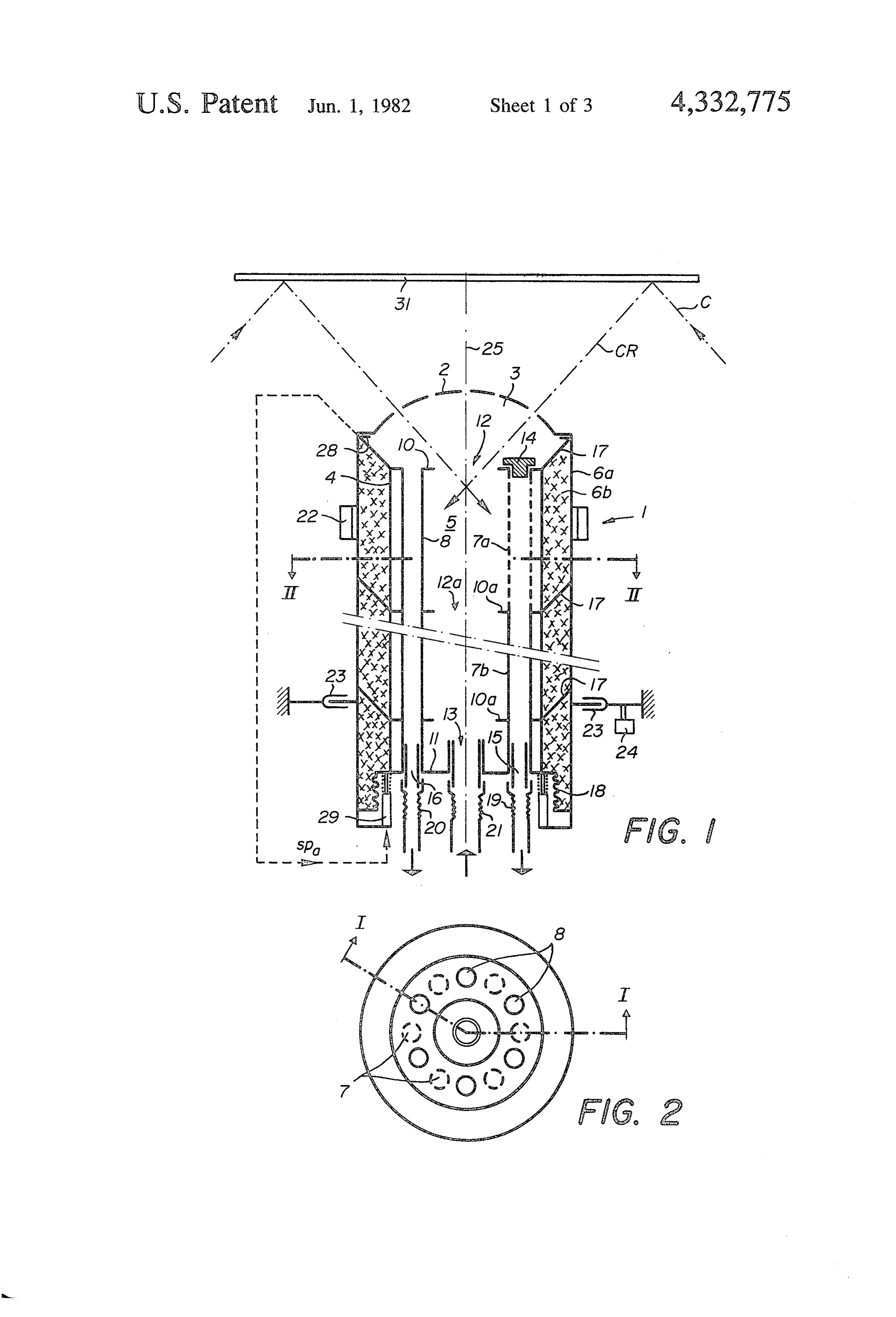
FIG. 1 shows a rotary tubular reactor represented in The tubes, 7, 8 will advantageously be fabricated longitudinal section along I-I in FIG. 2. from the same refractory materials, i.e. ZrO2 or Tho2, FIG. 2 shows a transverse section of this reactor and possibly Al2O3.
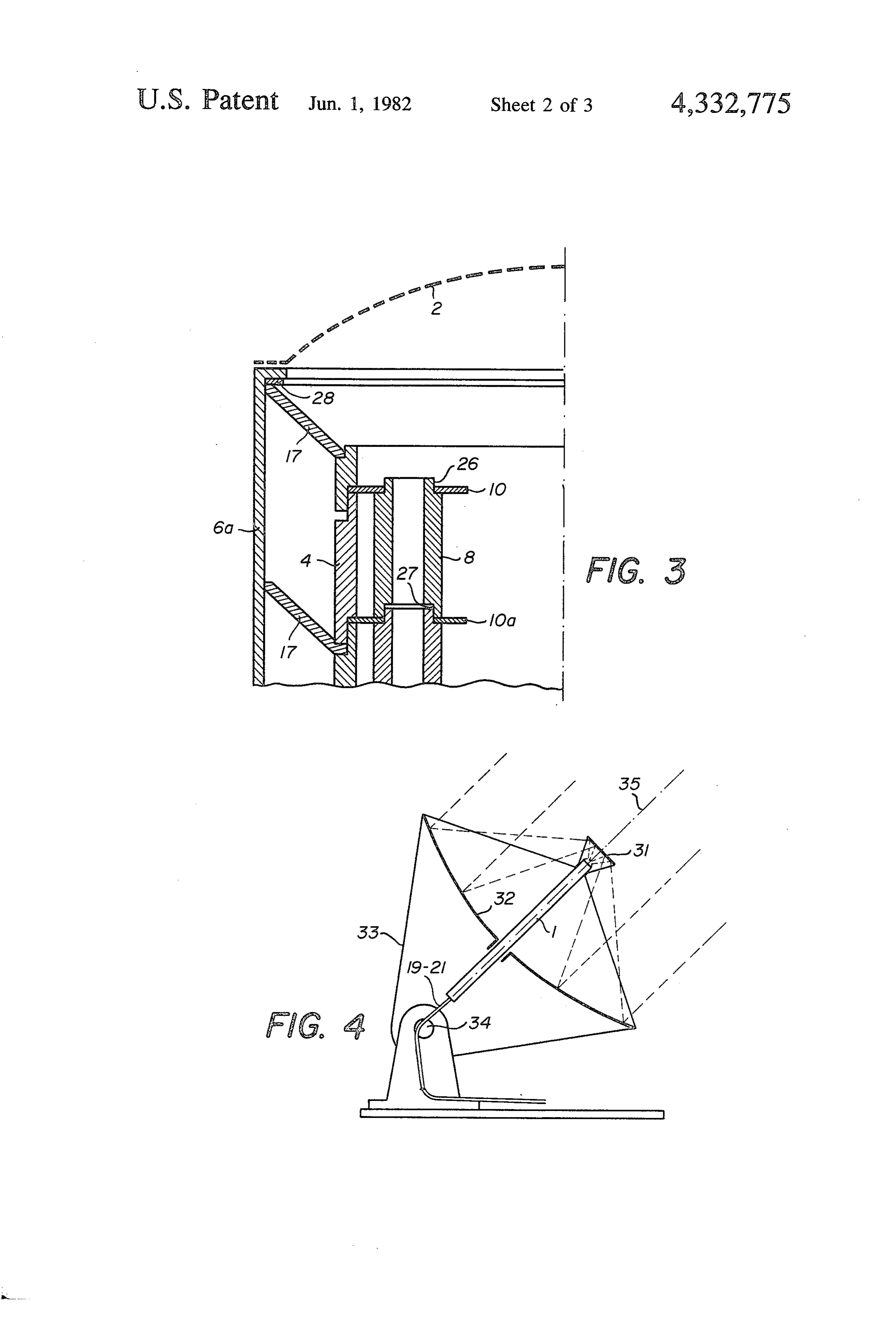
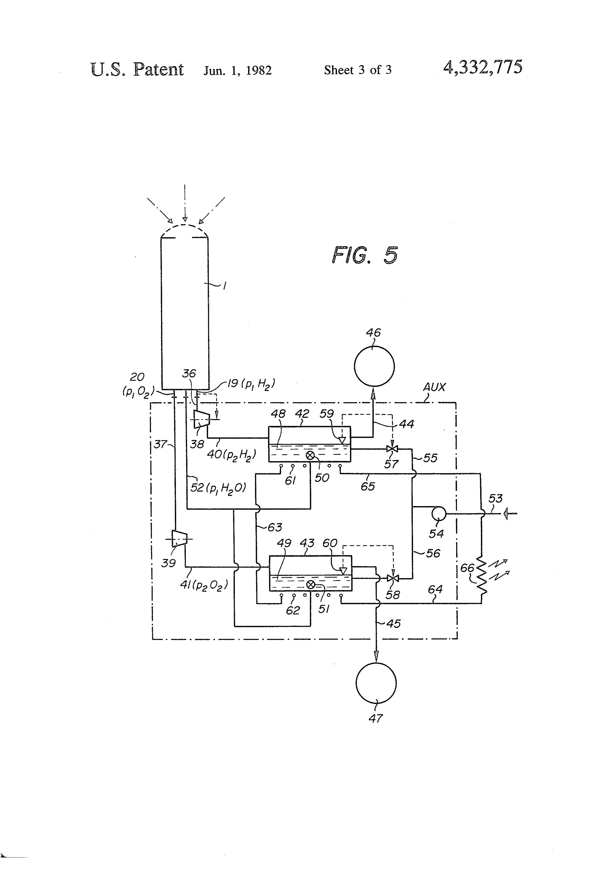
along II-II in FIG. . Frustoconical spacers 17 of a refractory material FIG. 3 shows in detail a mode of assembly for the 35 (ZrO2, ThC)2 or Al2O3) are also mounted on the exterior refractory elements of the reactor according to FIG. . of the tubular wall 4 in such a manner that they can slide FIG. 4 shows a diagram of a collector-concentrator axially in the external envelope 6a and maintain this system including the reactor according to FIG. 1. wall 4 in a coaxial position with respect to this envelope FIG. 5 shows a diagram of the hydrogen generator 6a.
comprising the reactor according to FIG. 1 combined 40 The transverse wall 11 is formed from a movable with an auxiliary low temperature system. plate connected in an impermeable manner via a bel PREFERRED EMBODEMENTS OF THE lows 18 to the lower end of the external envelope 6a of
INVENTION
the tubular reactor i.
The lower outlets 15 and 16 of the tubes 7 and 8 are
FIGS. 1 and 2 show, in longitudinal and transverse 45 also connected in an impermeable manner to flexible sections respectively, a hydrogen generator in the form tubular connections 19 and 20 respectively. Moreover, of a rotary tubular reactor 1 comprising a heating cham the inlet 13 is connected in an impermeable manner to a ber 5 bounded by an opaque refractory tubular wall 4 flexible tubular connection 21 for supplying water to be and by two transverse end walls 10, 11. dissociated.
This dissociation chamber 5 is provided with two 50 The upper end wall 10 forms an annular spacing disc series of refractory tubes 7, 8, whose ends are mounted of refractory material fixed to the internal surface of the on the transverse walls 10 and 11 respectively. tubular wall 4, provided with a central hole 12 consti This tubular reactor 1 has a receiving end for the tuting the said axial window, and with holes for posi concentrated solar radiation, which is covered by a tioning the corresponding tubes 7 and 8. transparent cap 2 and defines a collecting chamber 3 55 The tubes 7 and 8 are maintained parallel to one an communicating with the heating chamber 5 via an axial other with the aid of the said upper wall 10 as well as a window 2 provided in the transverse wall 10. series of annular spacing discs 10a arranged in a similar An inlet 13 for the water to be dissociated is arranged manner on this end wall 10, but at different intermediate on the other transverse wall 11, situated at the opposite positions along the dissociation chamber 5. The holes end of the tubular reactor . 60 12a of these discs 10a moreover correspond to the axial The tubes 7 constituting a first series each comprises window 12 of the end wall 0. This wall 10 and at least an upper end closed by a plug 14, a porous tubular the discs 10a situated in the upper part of the reactor, section 7a and an impermeable section 7b extending particularly in the vicinity of the porous sections 7a of along most of the tube 7 and constituting a preheating the tubes 7, are formed of a refractory material capable tube for the water to be dissociated. 65 of withstanding the high temperatures required to disso The plug 14 separates the interior of the tube 7 from ciate the water, and are preferably formed from ZrO2 or the collecting chamber 3. The porous section 7a is ar ThC2. The spacing discs 10a, which are situated in the ranged in such a way as to permit the preferential mo lower part of the reactor, are exposed to much lower
Page 8
temperatures and may be fabricated for example from As can be seen from FIG. 4, the tubular reactor 1 is Al2O3. mounted along this axis 35 of the large reflector 32 so The rotary tubular reactor 1 described above is rotat that they can pivot together about the axis 34. The small ably mounted on bearings 22 and 23 and is connected to reflector 31 is also arranged in a focal region of the large a drive mechanism 24 which causes it to rotate slowly reflector 32, opposite the cap 2 and window 12 arranged and at a regulable rate around its longitudinal axis 25. at the receiving end of the reactor 1. This drive mechanism 24 may comprise any suitable The flexible tubular connections 19 to 21 at the other motor, and in the present case is arranged so that it end of the reactor 1 are also connected to a low temper imparts an alternating rotary movement to the reactor 1 ature auxiliary system, which will be described below. corresponding to one complete revolution about its axis 10 The rotary tubular reactor 1 described above and 25, in both directions of rotation. The rotational veloc shown moreover in the diagram of FIG. 5 serves to ity of the reactor 1 may in this case be of the order of 1 ensure at the same time the preheating and dissociation revolution/minute for example. of water as well as the separation of the dissociated FIG. 3 shows a detail of a preferred mode of assem products, by molecular diffusion under Knudsen flow bly of the refractory elements 4, 7 and 8 of the reactor 15 conditions in the said porous tubular sections 7a, into two fractions H2-H2O and O2-H2O. These two frac 1 described above with reference to FIGS. 1 and 2.
As can be seen from FIG. 3, the refractory tubular tions consist of water vapour enriched with gaseous wall 4 as well as the refractory tubes 8 (and 7) are com hydrogen and gaseous oxygen respectively. All the component parts of the hydrogen generator posed of tubular segments forming modules that can be assembled simply by interlocking with one another. 20 which are at a high temperature during its operation are thus assembled within this rotary tubular reactor 1 it
To this end, each segment of a tube 7 or 8 has, respec self, which latter is moreover combined with a low tively, at its opposite ends an external constriction 26 temperature and a corresponding internal enlargement 27 enabling in FIG. 5. auxiliary system shown diagrammatically the segment to interlock with the following segment. 25 As can be seen from the diagram in FIG. 5, the said The discs 10 and 10a are perforated with holes of a tubular connections 19 and 20, which on the one hand diameter corresponding to the said constriction 26, in are connected to hydrogen and oxygen outlets 15 and such a way that each disc rests on a shoulder of the 16 respectively (FIG. 1), are on the other hand con corresponding constriction 26 of each segment of the nected by evacuation lines 36 and 37 respectively to two tubes 7 and 8, and is thus sandwiched between the inter 30 compressors 38 and 39.
locked segments. These two compressors 38 and 39 are provided with The tubular wall 4 is similarly composed of tubular means for regulating their outputs so that their inlet segments forming interlocked modules between which pressures p1H2 and p1O2 respectively can be regulated, the discs 10 and 10a as well as the frustoconical spacers and correspond to the regulable admission rates of the 17 are respectively sandwiched. 35 said H2-H2O and O2-H2O fractions evacuated re As is shown diagrammatically in FIGS. 1 and 3, a spectively from the reactor 1. These two fractions are pressure sensor 28 is arranged in such a manner at the compressed by the compressors 38 and 39 respectively upper end of the reactor 1, between the envelope 6a and and delivered at corresponding higher pressures p2H2 the frustoconical spacer 17 connected to the tubular and p2O2 via lines 40 and 41 to two condensers 42 and wall 4, that this sensor measures the axial pressure be 43.
tween this envelope and this wall, and transmits a corre The two condensers 42 and 43 serve respectively to sponding pressure signal spa. condense the water vapour contained in the said A servo-mechanism 29 is actuated by the said sensor H2-H2O and O2-H2O fractions so as thereby to sepa 28, as is indicated diagrammatically by the dotted line rate the hydrogen and oxygen, which are then delivered 30 in FIG. 1. It is arranged between the lower movable 45 respectively under pressure via respective outlet lines wall 11 and the lower end of the envelope 6a, so as to 44 and 45, for example to corresponding storage reser regulate the relative axial position of the wall 4 and voirs 46 and 47.
tubes 7, 8 with respect to this envelope 6a, as a function These two condensers 42 and 43 contain respectively of the said pressure signal spa, and thus maintain a low water baths 48 and 49 in which regulable pressure re predetermined axial pressure, of the order of 0.1 50 lease valves 50 and 51 are arranged in such a manner kg/cm2 for example, corresponding to a low predeter that they can withdraw from each bath a controllable mined longitidinal compressive force acting on the tu amount of water under pressure (p2H2, p2O2 respec bular wall 4. tively) and reduce the pressure of the water to a regula Finally, FIG. 1 shows a small reflector 31 serving to ble sub-atmospheric pressure, resulting in the evapora direct the solar radiation, concentrated 5000 to 10,000 55 tion of the water. The amount of heat required for this times, through the said transparent cap 2 and axial win evaporation in the pressure release valves 50 and 51 is dow 12 of the chamber 5, and onto the upper part of the thus provided by the baths 48 and 49 in which the said refractory tubes 7, 8. valves are immersed, with the result that these baths are This reflector 31 is part of a solar collecting-concen consequently cooled.
trating system, which will be described in more detail 60 The flashed water vapour thus obtained at the outlet hereinafter. of the valves 50 and 51 is recycled continuously under FIG. 4 shows a general diagram of the rotary tubular a regulable pressure p1H2O, through a recycle line 52 reactor 1 described above, associated with a solar col joined to the tubular connection 21, to the water inlet 13 lecting-concentrating system comprising a large mobile (FIG. 1) to the rotary tubular reactor 1. revolving parabolic reflector 32 which is mounted on a 65 A make-up water feedline 53 provided with a pump support 33 so as to be able to pivot about an axis 34 and 54 is also connected to two inflow lines 55 and 56 pro thus follow the sun so as to receive the solar radiation vided respectively with regulating valves 57 and 58 so parallel to its axis of symmetry 35. as to be able to provide regulable amounts of make-up
Page 9
water to the two baths 48 and 49, and thereby compen The reactor functions in the permanent operation sate for the amount of water continually dissociated in mode when the temperature y is sufficiently high to the reactor 1. allow the dissociation of the water, and when the con These two regulating valves 57 and 58 for the make densers are sufficiently hot to enable the water vapour up water may be automatically controlled by any suit to be injected at the chosen working pressure, able means, such as level sensors for the corresponding p1H2O=0.25 atmosphere, which corresponds to water bath, illustrated diagrammatically by the ele TD=2500 K., while the compressors 38 and 39 are ments 59 and 60 and functionally associated with these adjusted to the corresponding working pressures, valves 57 and 58, as is indicated diagrammatically by p1H2=0.025 atmosphere and p1O2=0.20 atmosphere, the dotted lines in FIG. 5. We are thus dealing in this 10 respectively.
case with a well-known type of level regulating device, Under these working conditions, a production of such as is used to regulate the level of water in a boiler. hydrogen of the order of 700 grams/hour is obtained for The condensers 42 and 43 are also associated respec an incident solar flux of 50 kW.
tively with an auxiliary cooling circuit, which is indi The rotary tubular reactor according to the inven cated diagrammatically by corresponding coils 61 and 15 tion, such as described above, is combined with a para 62 connected by lines 63, 64 and 65 to a cold source 66. bolic reflector so as to be able to concentrate the solar The latter enables all low temperature surplus heat to be radiation 5000 to 10,000 times in order for the reactor to evacuated from the afore-described auxiliary system achieve an acceptable efficiency at 2500 K. (Aux), so as to ensure the condensation and thus the The dimension of 8 m for the reflector diameter is the separation of all undissociated water contained in the 20 best value for adaptation to the standard supports pro said H2-H2O and O2-H2O fractions. This auxiliary vided for the heliostats of the revolving solar power cooling circuit 61 to 66 thus ensures in all cases the stations.
thermal balance of the whole of the afore-described This tubular reactor may constitute a modular unit generator, and enables hydrogen and oxygen to be re having all suitable dimensions to ensure a high effi covered separately and water to be recycled. 25
The hydrogen generator described above with refer nected toSeveral ciency.
modular units may moreover be con central unit containing all the low tempera ence to FIGS. 1 to 5 may by way of example have the ture auxiliary systems, so as thereby to ensure any large following characteristics: production of hydrogen that may be required. External diameter of the reactor (1)=30 cm It is clear that the compressors 38, 39 and the corre
sponding condensers 42, 43 described above may be
Internal diameter of the wall 4 (chamber 5)= 18 cm arranged in any suitable manner, for example in several Distribution of 6 tubes 7 alternating with 6 tubes 8 successive compression and condensation stages. over a circle 18 cm in diameter.
External diameter of the tubes 7, 8=2 cm, their wall by any suitable means, 39formay
The compressors 38, furthermore be driven example by turbines (not thickness=2 mm 35 and, their total length=about 5 m. shown) actuated by the vapour obtained by auxiliary Length of the porous tubular section 7a =30 cm exchange means, serving in particular to cool the enve Diameter of the small reflector 31 = 1 m lope 6a of the insulating casing 6, preferably in the Diameter of the large reflector 32=8 m. vicinity of the receiving end of the reactor 1, or serving The operation of the afore-described hydrogen gen O2-H2O 40 to cool the outlets 15 and 16 of the H2-H2O and erator may be explained in the following manner: fractions insufficiently cooled by their pas The working conditions for the functioning of the sage through the tubes 7 and 8. Thorium dioxide, ThC2, has particularly valuable reactor 1 under permanent operation will be chosen as advantages as refractory material for the construction follows in the present case: of the parts heated to high temperature in the rotary
tubular reactor forming the object of the present inven p1H2O=0.25 atmosphere; tion.
p1 O2=0.2 atmosphere; p2O2= 10 atmospheres; Thus, ThC2 has a melting point of the order of 3500 hydrogen suction pressure K., which leaves a good margin of safety (about 1000 p1H2=0.025 atmosphere; p2H2= 10 atmospheres; 50 K.) above the working temperature TD of 2500 K. dissociation temperature TD=2500 K. considered advantageous for the functioning of the In order to obtain economically the compression rotary tubular reactor according to the invention. ratios corresponding to these pressures, Roots type perature The good compressive strength of ThC2 at high tem compressors will for example be used. is advantageous, given the particular construc The reactor 1 may be started by the following opera 55 tion and mode of operation of the tubular reactor ac tions: cording to the invention, which essentially means that The compressors 38 and 39 are actuated, and the all its refractory tubular elements are only subjected to suction pressures are adjusted to a residual value less low compressive forces. In contrast, other construc than the selected working pressures (p1H2=0.025 atmo tions proposed in the state of the art, such as curved or sphere; p1O2=0.2 atmosphere), for example to 0.005 60 plane porous membranes, would be subjected to much atmosphere. higher stresses, in particular to bending forces. Water vapour is injected into the reactor at a pressure Moreover, ThC2 is one of the refractory materials corresponding to saturation at ambient temperature (for that is most stable and inert to oxidation and reduction example 0.05 atmosphere at 35 C.). by water vapour and its dissociation products at tem The concentrated solar radiation is applied progres 65 peratures up to 3000 K.
sively to the receiving end of the reactor 1, which is ThO2 thus ensures a good functioning under perma alternately turned by one complete revolution in one nent operation mode of the tubular reactor according to minute in both directions. the invention, that is to say without chemical reaction
Page 10
between Tho? and H2O and its dissociation products up a rotational movement comprising a complete revolu to at least 2500 K. tion of the reactor in one direction, then a complete Besides, ThC2 is inert above 2000 K. with respect to revolution in the opposite direction, and so on alter various other solid oxides such as MgO, ZrO2 and spi nately.
nel, and accordingly the connection of ThC)2 tubes in 6. The gas generator of claim 1, wherein the refrac the high temperature zone to tubes of the other oxides in tory lower end wall (11) includes conduits for introduc the low temperature and medium temperature zones ing water (13) into the reactor and for evacuating should not pose any particular problem. (15,16) the gases formed and collected therein, wherein Tho2 is only a weak absorber of light in the visible said lower wall (11) supports the tubes (7,8) for collect spectrum. However, the incorporation of an additive 10 ing the gases formed and is supported by yieldable such as CeO2 in very small amounts (S1%) should be means (18); thus enabling the tubes to freely extend sufficient to ensure the absorption of the solar radiation under heat by pushing said wall downward, which by the multiple reflections that occur by virtue of the prevents possible deformation.
particular disposition of the tubular reactor according 7. The generator of claim 1, wherein the tubes (7,8) to the invention, namely multiple reflections on the one 15 are for collecting the gases formed, said tubes being hand between the refractory tubes themselves, and on arranged axially and distributed along a circle, with the the other hand between these tubes and the refractory hydrogen collecting tubes (7) positioned alternately tubular wall that contains them. In fact, too strong an between the oxygen collecting tubes (8). absorption of the solar radiation would be undesirable 8. The generator of claim 1, wherein only the upper since it would promote thermal shocks, to which Tho? 20 part (7a) of each hydrogen collecting tube (7) is porous is relatively sensitive. and enables this gas to pass therethrough, the lower part We claim: thereof, as well as each oxygen collecting tube (8), 1. A gas generator for producing hydrogen and oxy acting as preheating means for the water to be dissoci gen from thermally dissociated water vapor, compris ated, such preheating occuring during contact with the ing 25 hot walls thereof.
a heat-insulated rotary tubular reactor (1) heated by 9. The generator of claim 1, comprising driving solar energy in incoming radiation (CR) from the means (24) and coupling means (23) therefor for rotat Sun, comprising ing the reactor (1) during operation to prevent bending an inner chamber (5), and possible collapse of the tubes (7,8) at high tempera inlet means (13) for providing water in the chamber, 30 ture.
an axial upper end wall (2) facing the incoming radia 10. A gas generator according to claim 1 wherein the tion and having the form of a transparent cap for said refractory tubes (7,8) are fitted into holes in a plu allowing the radiation to enter the inside of the rality of annular spacers (10a) for maintaining the rela reactor, tive positions of these tubes (7,8). a tubular side wall (4) and a flat lower end wall (11) 35 11. A gas generator according to claim 1, wherein the made of refractory material capable of absorbing a refractory tubes (7,8) comprise thorium dioxide or zir substantial portion of the collected radiation so as conia at least along an upper part of each tube. to raise, during operation, the temperature in the 12. A gas generator according to claim 1 or 11, inner chamber to a level sufficient to dissociate the wherein the refractory tubes (7,8) are arranged alter water therein to form hydrogen and oxygen, nately and distributed over a circle situated in the vicin means for separating the hydrogen from the oxygen, ity of the side wall (4).
comprising a plurality of substantially vertically 13. A gas generator according to claim 1, wherein a oriented refractory tubes (7,8) of which at least one reflector (31) is provided opposite the transparent cap (7) has a closed upper end (14) but a partially po (2) and positioned to receive a converging beam (C) of rous wall (7a) for letting the hydrogen preferen 45 concentrated solar radiation and reflect the radiation in tially penetrate therein, and another tube (8) has a a reflected convergent beam (CR) directed through the solid wall and an open upper end for collecting the transparent cap (2) and concentrated on a central win oxygen, and dow (12) in the reactor (1).
a lower end (15,16) of each tube being connected to 14. A gas generator according to claim 13, compris means for evacuating and storing the gases formed 50 ing also a parabolic reflector (32) having the same axis and collected therein. of symmetry (35) as that of the reactor (1) and that of 2. A gas generator according to claim 1, wherein the the reflector (31), all being mounted integral with one porous section (7a) of each porous-walled tube (7) com another on a support (33); and means for pivoting the prises a refractory oxide having a porosity of about 10 support to direct the parabolic reflector (32) toward the to 30% and a pore diameter of about 5 to 50 pum. 55 sun so as to receive the radiation parallel to its axis of 3. A gas generator according to claim 1, comprising symmetry, and to direct the converging beam of con also a servo-mechanism (29) communicating with the centrated solar radiation (C) onto the reflector (31), and lower end wall (11) and controlled by a pressure sensor thus form a reflected converging beam (CR) concen (28) responsive to the axial pressure on the upper end of trated on the central window (12) in the reactor (1). the tubular side wall (4) to maintain this pressure at a 60 15. A gas generator according to claim 14, wherein predetermined low value. the reflectors (31,32) are constructed and arranged to 4. A gas generator according to claim 1, wherein the concentrate the solar radiation at least about 5000 times. refractory side wall (4) is positioned by a plurality of 16. A hydrogen generator according to claim 1, frustoconical spacers (17) fixed to the external surface wherein the tubular wall (4) and the refractory tubes of this wall (4), between the latter and an external gas 65 (7,8) are formed of sections of modular tubes whose tight enclosure (6a). opposite ends have respectively external constrictions 5. A gas generator according to claim 1, comprising (26) and corresponding internal enlargements (27) for also driving means (24) for imparting to the reactor (1) interlocking adjacent sections with one another.
Page 11
17. A gas generator according to claim 16, wherein the said refractory tubes (7.8) are fitted into holes in a each said spacer (10a) is positioned between the inter plurality of annular spacers (10a) for maintaining the locked ends of successive tube sections. relative positions of these tubes (7,8).
18. A gas generator according to claim 17, wherein 5 : : k : :
Provenance
- Collection
- Cited prior art
- Original PDF
- patentimages.storage.googleapis.com →
- Filed
- 1978-11-03
- Pages
- 11
- Method
- pdftotext (the PDF's own text layer) + pdftoppm 300dpi page scans
- Source
- Google Patents bibliographic record
- Granted
- 1982-06-01
- Inventors
- Pierre Genequand; Daniel M. Gross; Battelle Memorial Institute Inc
- Transcribed from
- patentimages.storage.googleapis.com →