patent · US20080199744A1
Hydrogen generating apparatus, fuel cell power generation system, method of controlling hydrogen generating quantity and recorded medium recorded program performing the same
21 August 2008
Page 1 — bibliographic record
(19) United States (12) Patent Application Publication (10) Pub. No.: US 2008/0199744 A1
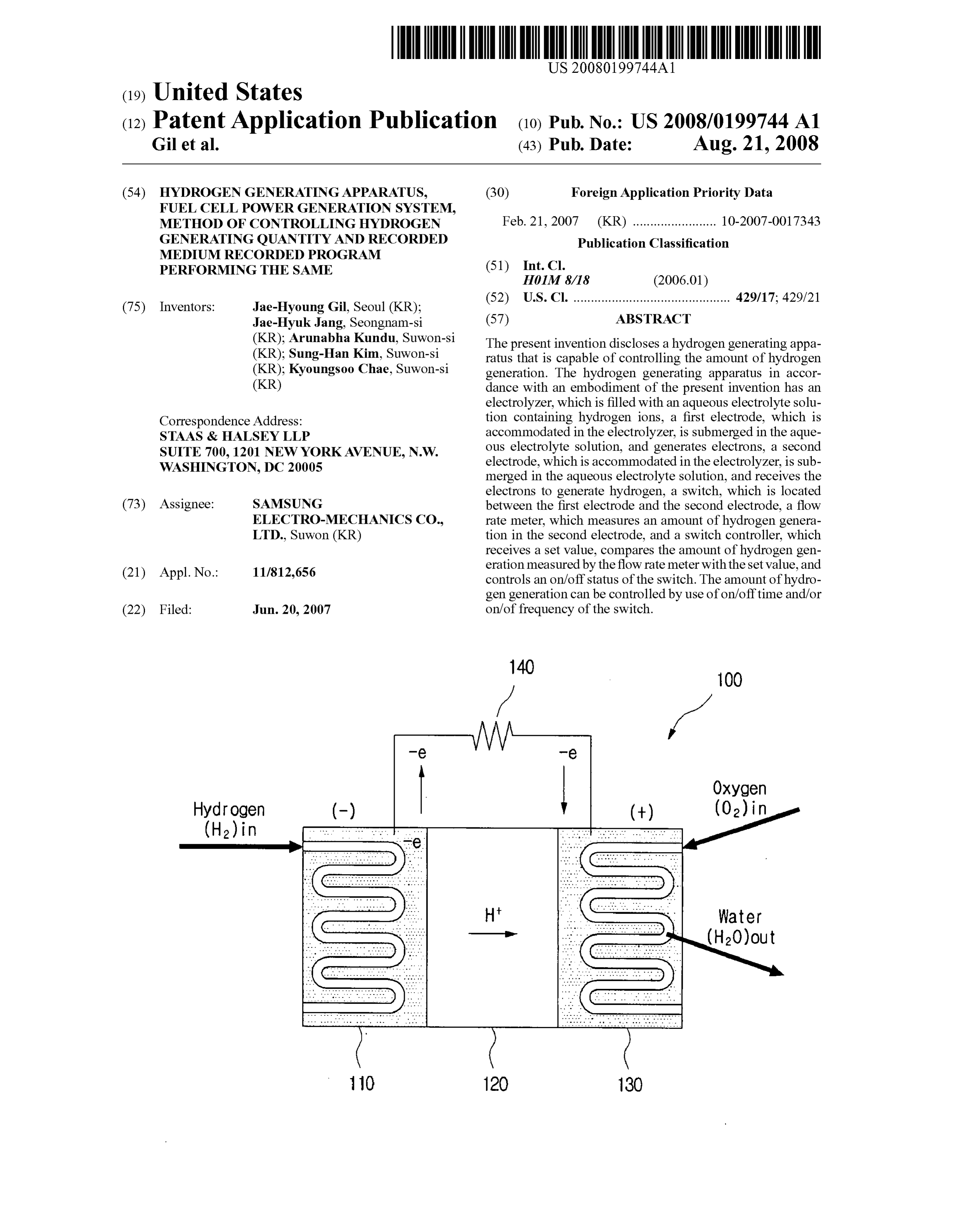
Gil et al. (43) Pub. Date: Aug. 21, 2008 (54) HYDROGENGENERATINGAPPARATUS, (30) Foreign Application Priority Data
FUEL CELL POWER GENERATION SYSTEM,
METHOD OF CONTROLLING HYDROGEN Feb. 21, 2007 (KR) ........................ 10-2007-OO17343 GENERATING QUANTITY AND RECORDED Publication Classification
MEDIUM RECORDED PROGRAM
PERFORMING THE SAME (51) Int. Cl.
52) U.S. Cl. ............................................. 429/17:429721 (75) Inventors: Jae-Hyoung Gil, Seoul (KR): (52) s Jae-Hyuk Jang, Seongnam-si (57) ABSTRACT
(KR); Arunabha Kundu, Suwon-si The present invention discloses a hydrogen generating appa (KR); Sung-Han Kim, Suwon-si ratus that is capable of controlling the amount of hydrogen (KR); Kyoungsoo Chae, Suwon-si generation. The hydrogen generating apparatus in accor (KR) dance with an embodiment of the present invention has an electrolyzer, which is filled with an aqueous electrolyte solu
Correspondence Address: tion containing hydrogen ions, a first electrode, which is STAAS & HALSEY LLP accommodated in the electrolyzer, is submerged in the aque SUTE 700 1201 NEW YORKAVENUE. N.W. ous electrolyte Solution, and generates electrons, a second WASHINGTON DC2OOOS L vs 7 ye electrode, which is accommodated in the electrolyzer, is sub 9 merged in the aqueous electrolyte solution, and receives the electrons to generate hydrogen, a Switch, which is located (73) Assignee: SAMSUNG between the first electrode and the second electrode, a flow ELECTRO-MECHANICS CO., rate meter, which measures an amount of hydrogen genera LTD., Suwon (KR) tion in the second electrode, and a switch controller, which receives a set value, compares the amount of hydrogen gen eration measured by the flow rate meter with the set value, and (21) Appl. No.: 11/812,656 controls an on/off status of the switch. The amount of hydro gen generation can be controlled by use of on/off time and/or (22) Filed: Jun. 20, 2007 on/offrequency of the switch.
Page 2
Drawing sheet — no readable text.
Page 3
Drawing sheet — no readable text.
Page 4
Drawing sheet — no readable text.
Page 5
Drawing sheet — no readable text.
Page 6
Drawing sheet — no readable text.
Page 7
Drawing sheet — no readable text.
Page 8
Drawing sheet — no readable text.
Page 9
Drawing sheet — no readable text.
Page 10
Drawing sheet — no readable text.
Page 11
Drawing sheet — no readable text.
Page 12
Drawing sheet — no readable text.
Page 13
Drawing sheet — no readable text.
Page 14
Drawing sheet — no readable text.
Page 15
Drawing sheet — no readable text.
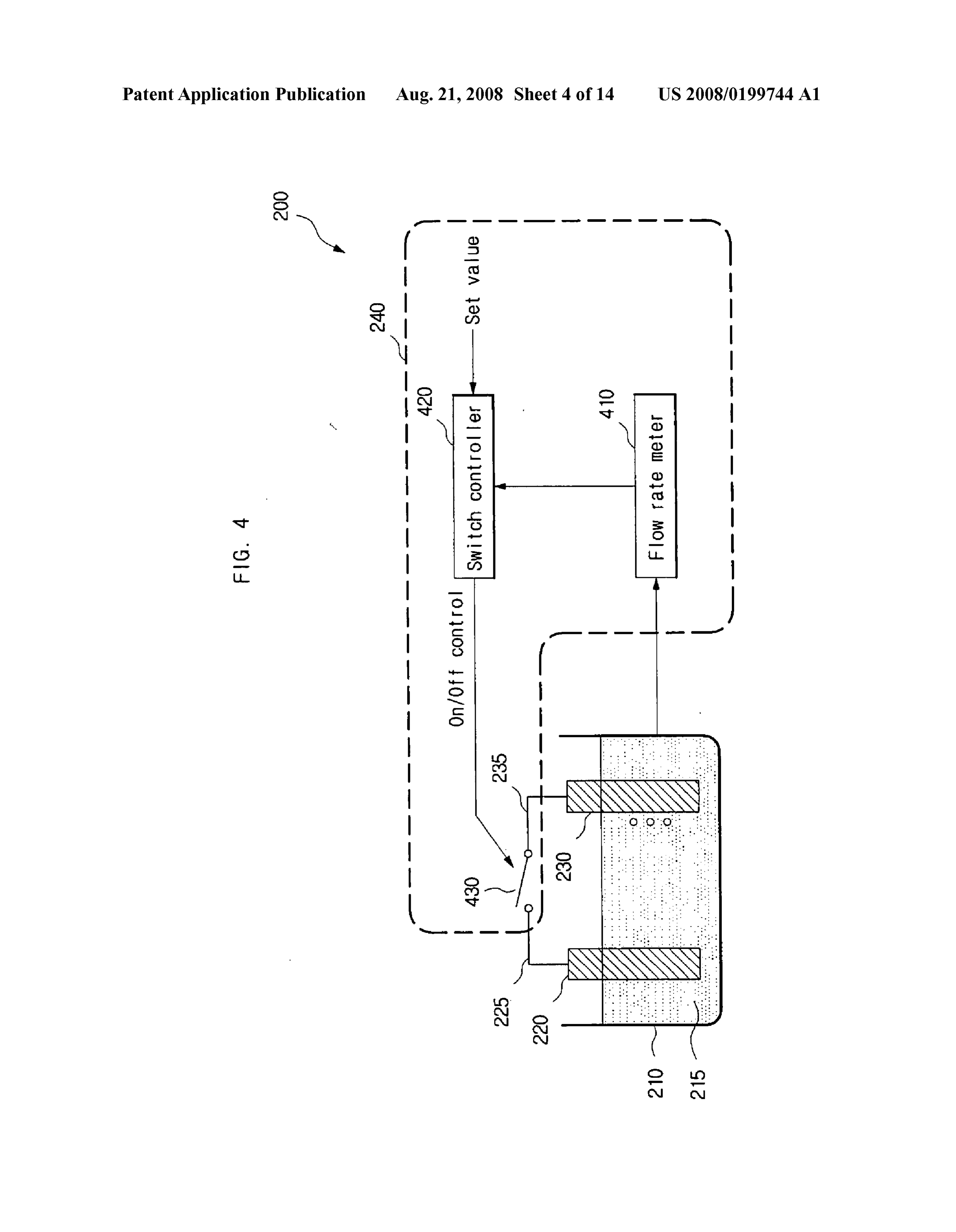
Page 16
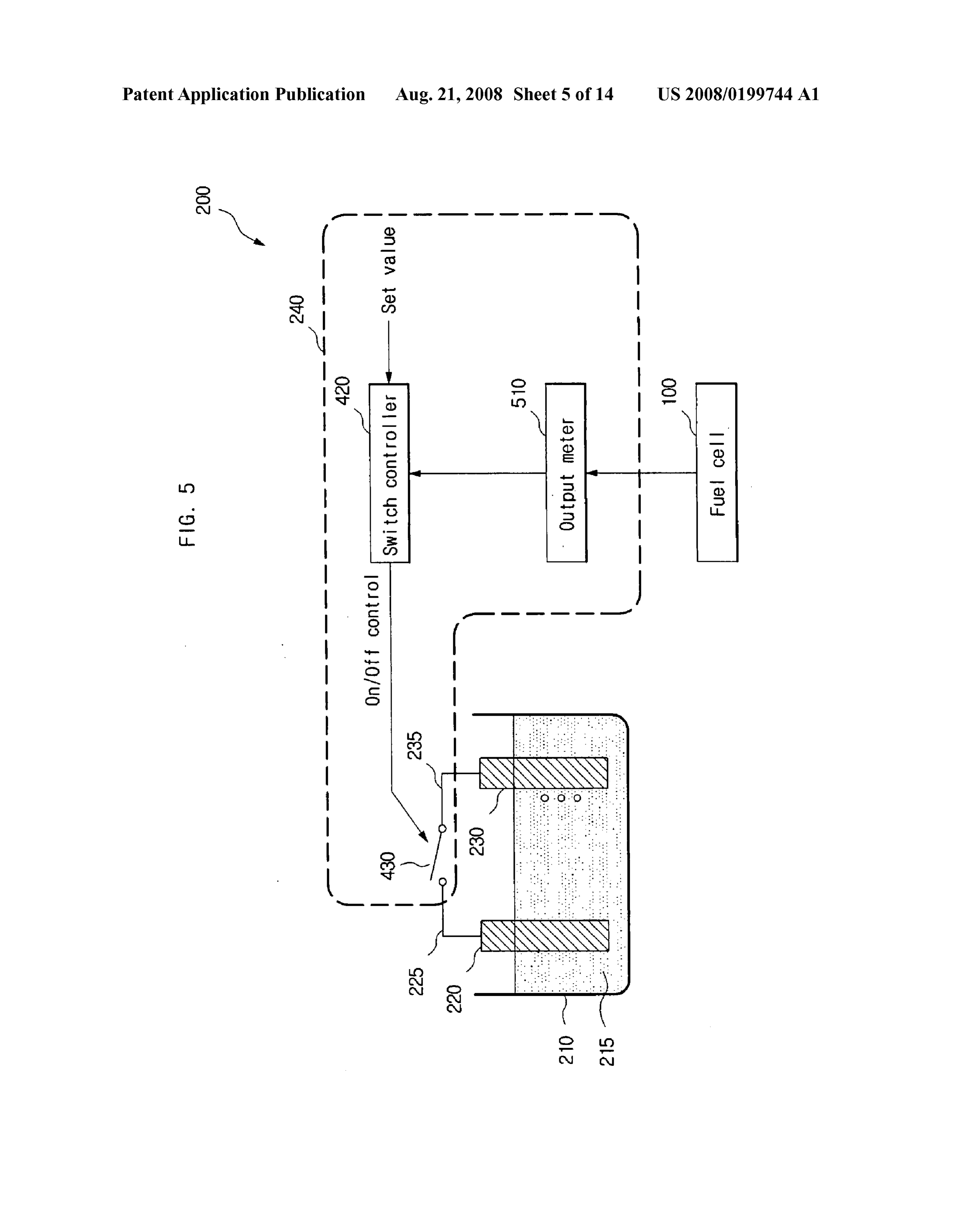
US 2008/O 199744 A1 Aug. 21, 2008
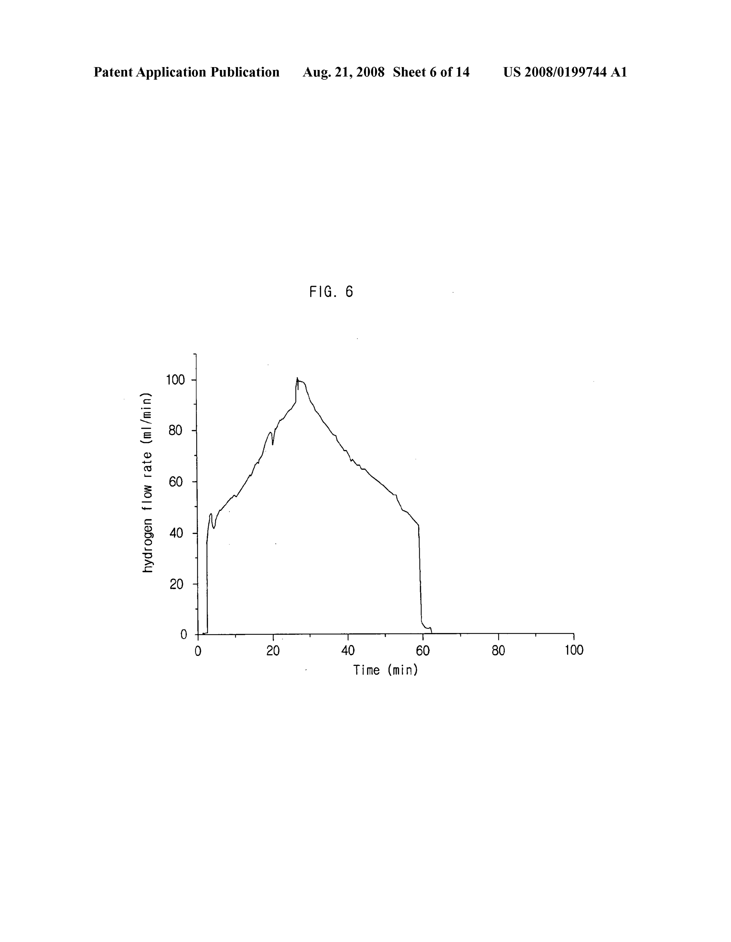
HYDROGENGENERATINGAPPARATUS, 0012 However, the former case requires a high reforming FUEL CELL POWER GENERATION SYSTEM, temperature, has a complicated system, consumes driving METHOD OF CONTROLLING HYDROGEN power, and contains impurities (e.g., CO and CO) in addition GENERATING QUANTITY AND RECORDED to pure hydrogen. The latter case deteriorates power density MEDIUM RECORDED PROGRAM due to a low rate of a chemical reaction in the anode and a PERFORMING THE SAME cross-over of hydrocarbon through the membrane. BACKGROUND OF THE INVENTION SUMMARY OF THE INVENTION
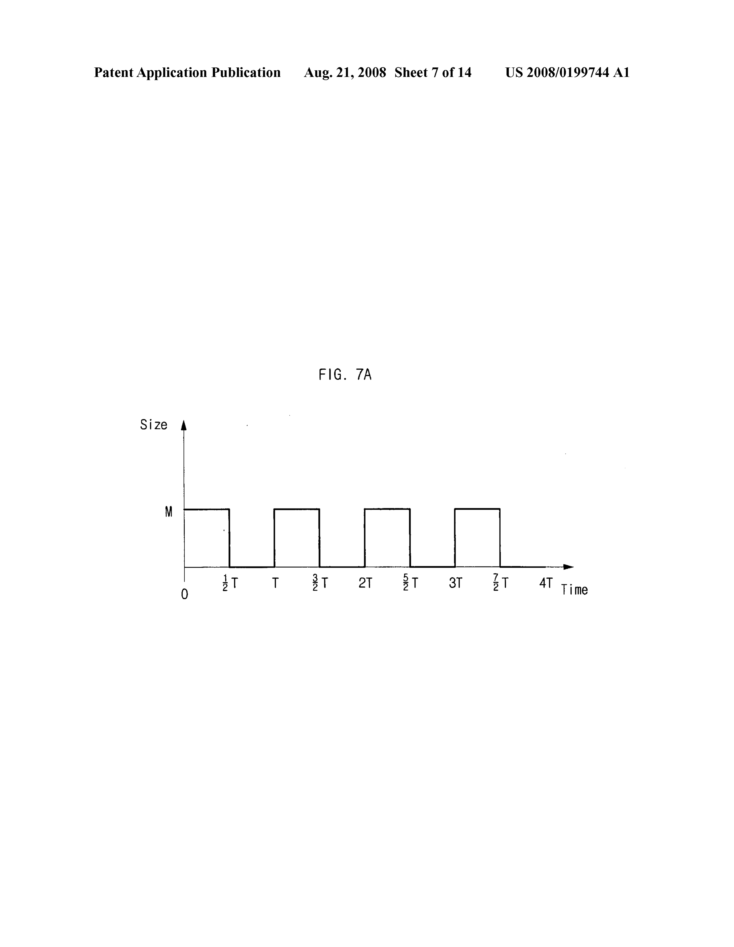
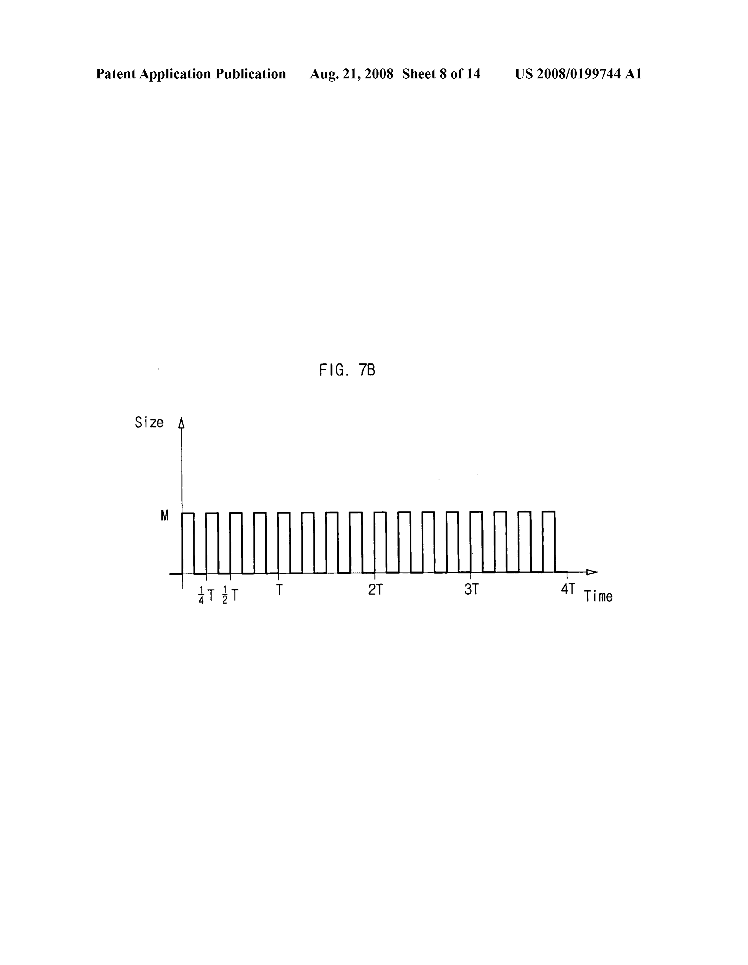
0001 1. Field of the Invention 0013 The present invention provides a hydrogen generat 0002 The present invention relates to a hydrogen gener ing apparatus, a fuel cell power generation system, a method ating apparatus, more particularly to a hydrogen generating of controlling the quantity of hydrogen generation, and a apparatus that can control the amount of generation of hydro recorded medium recorded with a program performing the gen Supplied to a fuel cell. method that can generate pure hydrogen at room temperature 0003 2. Background Art through an electrochemical reaction. 0004. A fuel cell refers to an energy conversion apparatus 0014. The present invention also provides a hydrogen gen that directly converts chemical energy of a fuel (hydrogen, erating apparatus, a fuel cell power generation system, a LNG, LPG, methanol, etc.) and air to electricity and/or heat method of controlling the quantity of hydrogen generation, by means of an electrochemical reaction. Unlike a conven and a recorded medium recorded with a program performing tional power generation technology that requires fuel com the method that can control the quantity of hydrogen genera bustion, steam generation, or a turbine or power generator, the tion without a separate BOP (Balance of Plant) unit while fuel cell technology needs no combustion process or driving maintaining a simple structure. device, thereby boosting energy efficiency and curbing envi 0015 The present invention also provides a hydrogen gen ronmental problems. erating apparatus, a fuel cell power generation system, a 0005 FIG. 1 illustrates an operational architecture of a method of controlling the quantity of hydrogen generation, fuel cell. and a recorded medium recorded with a program performing 0006 Referring to FIG.1, a fuel cell 100 is composedofan the method that are economical and eco-friendly. anode as a fuel pole 110 and a cathode as an air pole 130. The 0016. The present invention also provides a hydrogen gen fuel pole 110 is provided with hydrogen molecules (H), and erating apparatus, a fuel cell power generation system, a decomposes them into hydrogen ions (H) and electrons (e). method of controlling the quantity of hydrogen generation, The hydrogen ion (H) moves toward the air pole 130 via a and a recorded medium recorded with a program performing membrane 120, which is an electrolyte layer. The electron the method that can control the quantity of hydrogen genera moves through an external circuit 140 to generate an electric tion by use of On/Off time and/or On/Off frequency of a current. In the air pole 130, the hydrogen ions and the elec switch.
trons are combined with oxygen molecules in the atmosphere, 0017 Moreover, the present invention provides a hydro generating water molecules. The following chemical formu gen generating apparatus, a fuel cell power generation sys las represent the above chemical reactions occurring in the tem, a method of controlling the quantity of hydrogen gen fuel cell 100. eration, and a recorded medium recorded with a program
performing the method that can prevent waste or risk of leaking Surplus hydrogen in the air simply by turning on the
Airpole 130: /2 O+2H+2e->HO Switch and reduce the noise and power consumption by not using a gas pump or a liquid pump.
Overall reaction: H+1/2 O-->H-0 Chemical Formula 1 0018. An aspect of the present invention features a hydro gen generating apparatus that is capable of controlling the 0007. In short, the fuel cell 100 functions as a battery by amount of hydrogen generation.
Supplying the electric current, generated due to the flowing of 0019. The hydrogen generating apparatus in accordance the decomposed electrons, to the external circuit 140. Such a with an embodiment of the present invention includes an fuel cell 100 hardly emits an atmospheric pollutant such as electrolyzer, which is filled with an aqueous electrolyte solu Sox and NOx and makes little noise and vibration.
tion containing hydrogen ions, a first electrode, which is 0008 Meanwhile, in order to produce electrons in the fuel accommodated in the electrolyzer, is submerged in the aque pole 110, the fuel cell 100 necessitates a hydrogen generating ous electrolyte Solution, and generates electrons, a second apparatus that can change a common fuel to hydrogen gas. electrode, which is accommodated in the electrolyzer, is sub 0009. A hydrogen storage tank, generally known as a merged in the aqueous electrolyte solution, and receives the hydrogen generating apparatus, however, occupies a large electrons to generate hydrogen, a Switch, which is located space and should be kept with care. between the first electrode and the second electrode, a flow 0010 Moreover, as a portable electronic device, such as a rate meter, which measures an amount of hydrogen genera mobile phone and a notebook computer, requires a large tion in the second electrode, and a switch controller, which capacity of power, it is necessary that the fuel cell have a large receives a set value, compares the amount of hydrogen gen capacity and perform high performance while it is Small. eration measured by the flow rate meter with the set value, and 0011. In order to meet the above needs, methanol or for controls an on/off status of the Switch. mic acid, permitted to be brought into an airplane by Interna 0020. The switch controller can be inputted with the set tional Civil Aviation Organization (ICAO), is used for fuel value directly from a user through an input unit. The hydrogen reforming, or methanol, ethanol, or formic acid is directly generating apparatus can be coupled to a fuel cell and Supplies used as a fuel for the fuel cell. hydrogen, and the switch controller can be inputted with the
Page 17
US 2008/O 199744 A1 Aug. 21, 2008
set value in accordance with an amount of hydrogen genera 0028. The metal forming the first electrode can have a tion that is required by the fuel cell. higher ionization tendency than a metal forming the second 0021. The metal forming the first electrode can have a electrode.
higher ionization tendency than a metal forming the second 0029. The switch controller can generate and output a electrode. Switch control signal turning the Switch on and off, and the switch controller can determine an on/off ratio of the switch 0022. The flow rate meter can measure the amount of within one cycle by varying a duty ratio of the switch control hydrogen generation in units of flowrate. The Switch control signal. The meter can be a flow rate meter that measures the ler can generate and output a Switch control signal turning the amount of hydrogen generated in the second electrode in switch on and off, and the switch controller can determine an units of flowrate. The switch controller can control a fluctua on/off ratio of the switch within one cycle by varying a duty tion in the amount of hydrogen generation by varying an ratio of the Switch control signal. on/off frequency of the switch control signal. The switch 0023 The switch controller can control a fluctuation in the controller can compare the set value with the measured amount of hydrogen generation by varying an on/off fre amount of hydrogen generation, and can increase the duty quency of the Switch control signal. The Switch controller can ratio if the amount of hydrogen generation is Smaller than the compare the set value with the measured amount of hydrogen set value, reduce the duty ratio if the amount of hydrogen generation, and can increase the duty ratio if the amount of generation is greater than the set value, and maintain the duty hydrogen generation is Smaller than the set value, reduce the ratio if the amount of hydrogen generation is equal to the set duty ratio if the amount of hydrogen generation is greater than value. The set value can include an upper limit and a lower the set value, and maintain the duty ratio if the amount of limit, and the switch controller can compare the set value with hydrogen generation is equal to the set value. The set value the measured amount of hydrogen generation, and can includes an upper limit and a lower limit, and the Switch increase the duty ratio if the amount of hydrogen generation controller can compare the set value with the measured is smaller than the lower limit, reduce the duty ratio if the amount of hydrogen generation is greater than the upper limit, amount of hydrogen generation, and can increase the duty and maintain the duty ratio if the amount of hydrogen gen ratio if the amount of hydrogen generation is Smaller than the eration is between the lower limit and the upper limit. lower limit, reduce the duty ratio if the amount of hydrogen 0030 The meter can be an output meter that measures an generation is greater than the upper limit, and maintain the output of the fuel cell in units of watt (W), volt (V), ampere duty ratio if the amount of hydrogen generation is between the (A), ohm (S2) or a combination thereof. The Switch controller lower limit and the upper limit. can control a fluctuation in the output of the fuel cell by 0024. Another aspect of the present invention features a varying an on/off frequency of the Switch control signal. The fuel cell power generation system including a hydrogen gen switch controller can compare the set value with the measured erating apparatus that is capable of controlling the amount of output of the fuel cell, and can increase the duty ratio if the hydrogen generation. output of the fuel cell is smaller than the set value, reduce the 0025. The fuel cell power generation system in accor duty ratio if the output of the fuel cell is greater than the set dance with an embodiment of the present invention has a value, and maintain the duty ratio if the output of the fuel cell hydrogen generating apparatus, which controls an amount of is equal to the set value. The set value can include an upper hydrogen generation by controlling an on/off status of a limit and a lower limit, and the Switch controller can compare switch connected between electrodes, and a fuel cell, which is the set value with the measured output of the fuel cell, and can Supplied with hydrogen generated by the hydrogen generat increase the duty ratio if the output of the fuel cell is smaller ing apparatus and produces a direct current by converting than the lower limit, reduce the duty ratio if the output of the chemical energy of the hydrogen to electrical energy. fuel cell is greater than the upper limit, and maintain the duty 0026. The hydrogen generating apparatus can include an ratio if the output of the fuel cell is between the lower limit electrolyzer, which is filled with an aqueous electrolyte solu and the upper limit.
tion containing hydrogen ions, a first electrode, which is 0031. Another aspect of the present invention features a accommodated in the electrolyzer, is submerged in the aque method of controlling an amount of hydrogen generation in a ous electrolyte solution, and generates electrons, a second hydrogen generating apparatus controlling an amount of electrode, which is accommodated in the electrolyzer, is sub hydrogen generation by controlling an on/off status of a merged in the aqueous electrolyte solution, and receives the switch located between electrodes.
electrons to generate hydrogen, a Switch, which is located 0032. The method of controlling an amount of hydrogen between the first electrode and the second electrode, a meter, generation in accordance with an embodiment of the present which measures an amount of hydrogen generation or an invention includes the steps of being inputted with a set value; output of a fuel cell, and a switch controller, which receives a comparing a measured amount of hydrogen generation and set value, compares the amount of hydrogen generation or the the set value; and increasing a duty ratio of a Switch control output of the fuel cell measured by the meter with the set signal if the amount of hydrogen generation is Smaller than value, and controls an on/off status of the switch. the set value, reducing the duty ratio of the switch control 0027. The switch controller can be inputted with the set signal if the amount of hydrogen generation is greater than the value directly from a user through an input unit. The hydrogen set value, and maintaining the duty ratio of the Switch control generating apparatus can be coupled to the fuel cell and signal if the amount of hydrogen generation is equal to the set Supply hydrogen, and the Switch controller can be inputted value, in which the switch control signal controls the on/off with the set value in accordance with an amount of electric status of the switch within one cycle in accordance with the power, Voltage, current, impedance or a combination thereof duty ratio.
or an amount of hydrogen generation that is required by the 0033. The method of controlling an amount of hydrogen fuel cell. generation in accordance with another embodiment of the
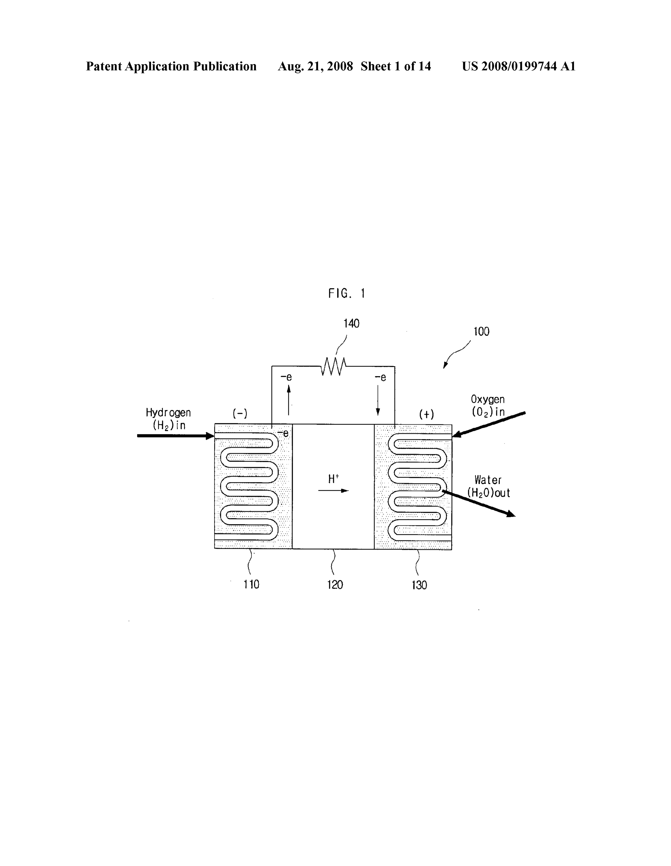
Page 18
US 2008/O 199744 A1 Aug. 21, 2008
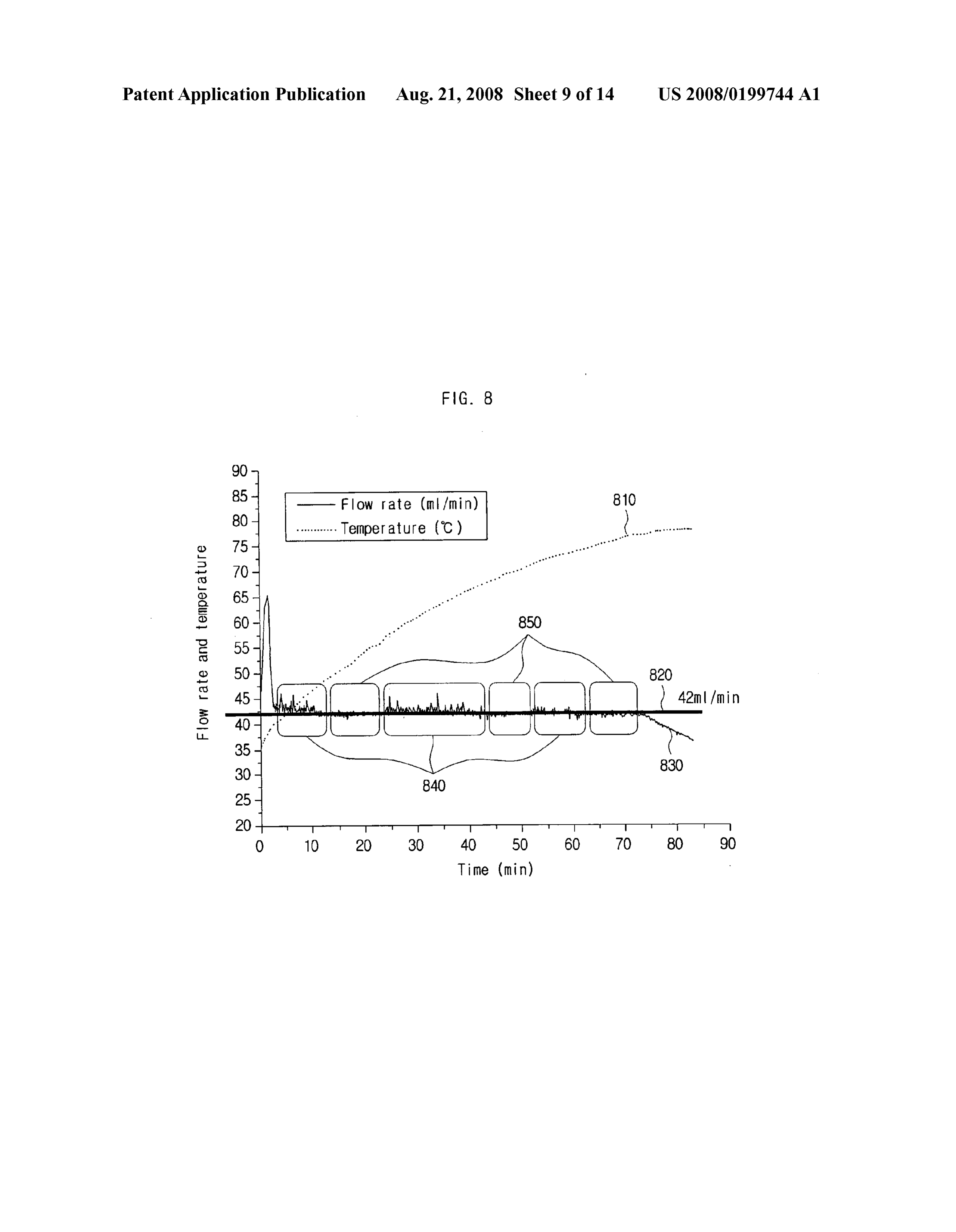
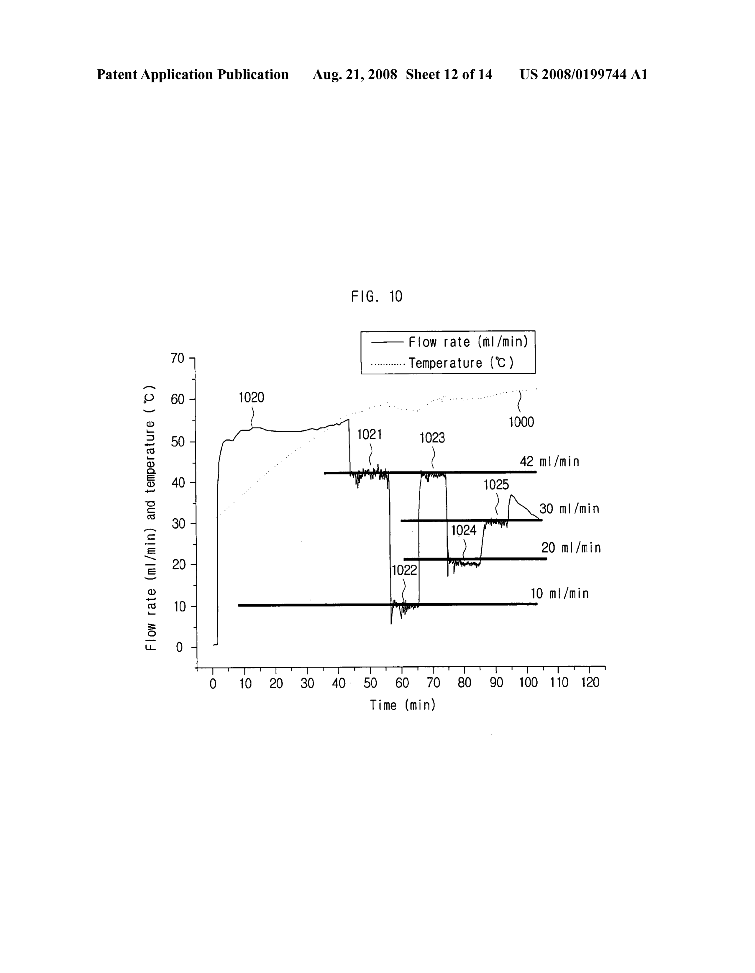
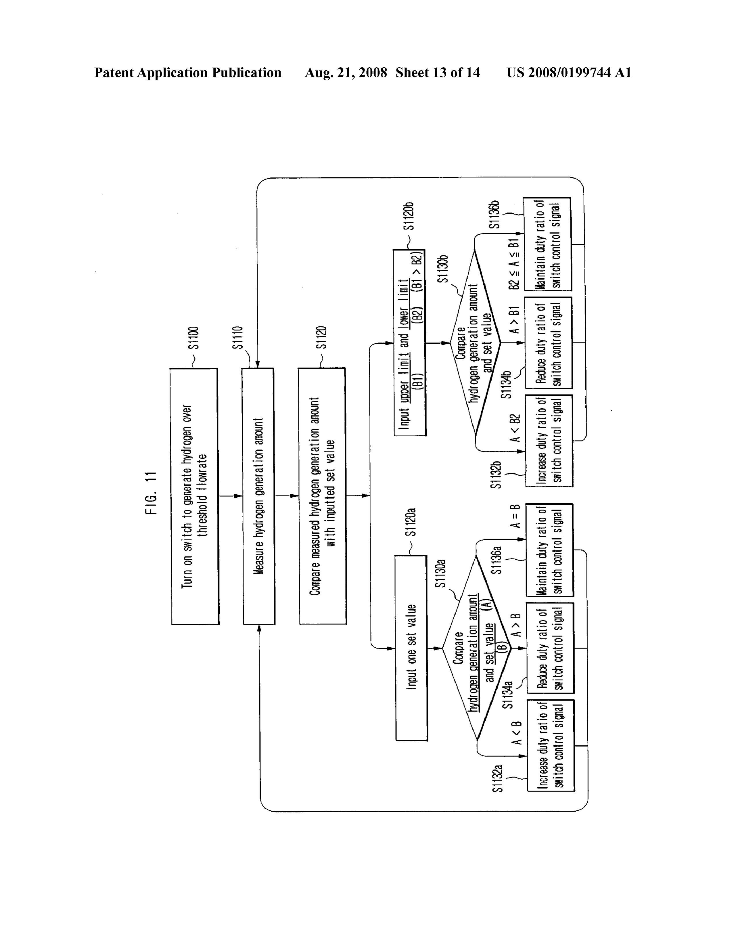
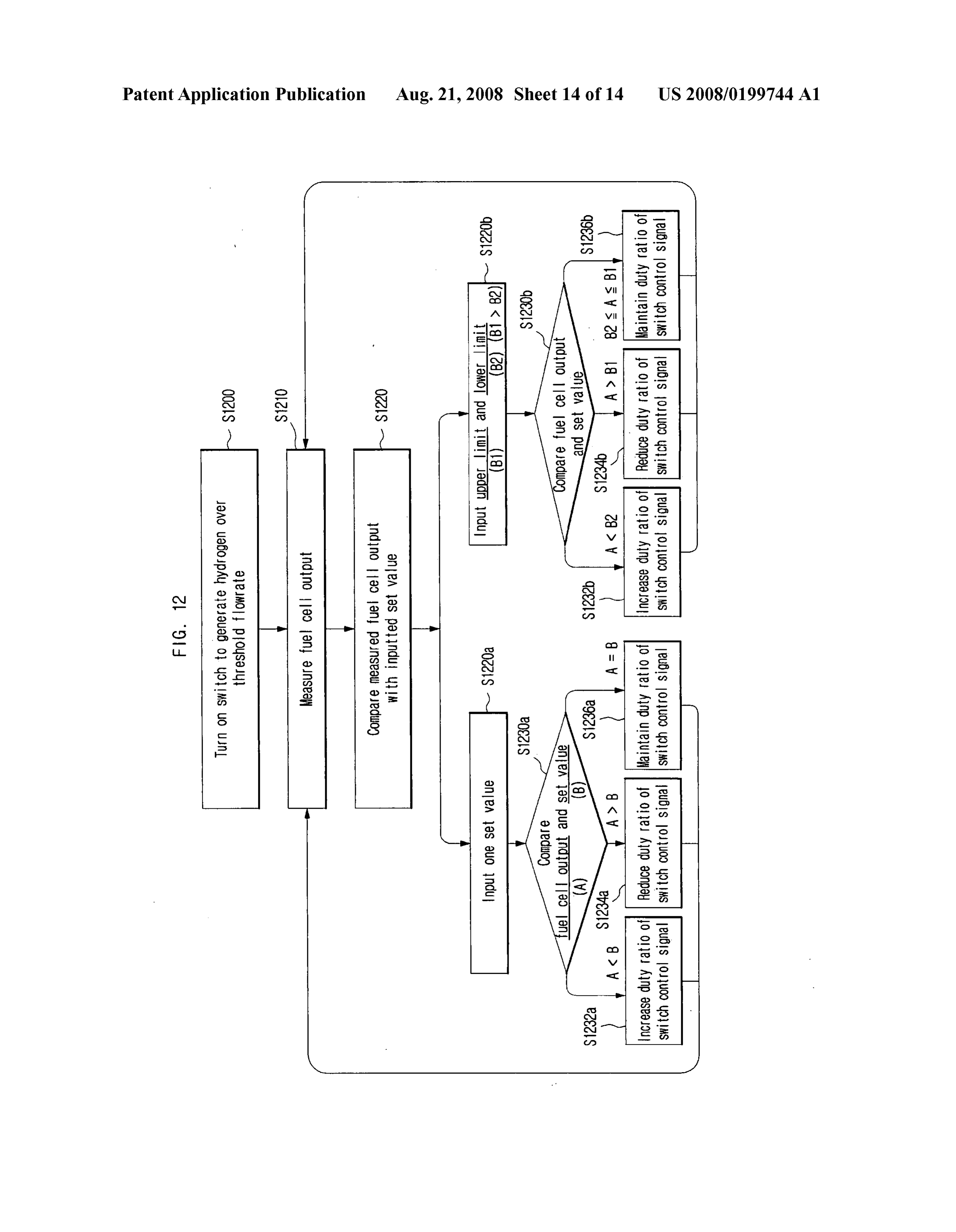
present invention includes the steps of being inputted with an 0041 FIG. 4 shows a block diagram of a control unit of a upper value and a lower value; comparing a measured amount hydrogen generating apparatus in accordance with an of hydrogen generation with the upper value and the lower embodiment of the present invention; value; and increasing a duty ratio of a Switch control signal if 0042 FIG. 5 shows a block diagram of a control unit of a the amount of hydrogen generation is Smaller than the lower hydrogen generating apparatus in accordance with another value, reducing the duty ratio of the Switch control signal if embodiment of the present invention; the amount of hydrogen generation is greater than the upper 0043 FIG. 6 is a graph indicating quantities of generated value, and maintaining the duty ratio of the Switch control hydrogen, expressed in flow rate, when the Switch is turned signal if the amount of hydrogen generation is between the On, lower value and the upper value, in which the switch control 0044 FIG. 7a shows a first example of On/Off frequencies signal controls the on/offstatus of the switch within one cycle of the Switch of a hydrogen generating apparatus in accor in accordance with the duty ratio. dance with an embodiment of the present invention; 0034. The method of controlling an amount of hydrogen 004.5 FIG.7b shows a second example of On/Off frequen cies of the Switch of a hydrogen generating apparatus in generation in accordance with yet another embodiment of the accordance with an embodiment of the present invention; present invention includes the steps of being inputted with a 0046 FIG. 8 shows the relation between time and quantity set value; comparing an output of the fuel cell and the set of hydrogen generation when the On/Off frequency of the value; and increasing a duty ratio of a Switch control signal if switch is controlled;
the output of the fuel cell is smaller than the set value, reduc 0047 FIG. 9a shows a first example of duty ratios of the ing the duty ratio of the switch control signal if the output of Switch of a hydrogen generating apparatus in accordance with the fuel cell is greater than the set value, and maintaining the an embodiment of the present invention; duty ratio of the switch control signal if the output of the fuel 0048 FIG.9b shows a second example of duty ratios of the cell is equal to the set value, in which the Switch control signal Switch of a hydrogen generating apparatus in accordance with controls the on/off status of the switch within one cycle in an embodiment of the present invention; accordance with the duty ratio. 0049 FIG. 10 shows the relation between time and quan 0035. The method of controlling an amount of hydrogen tity of hydrogen generation when the duty ratio of the switch generation in accordance with yet another embodiment of the is controlled;
present invention includes the steps of being inputted with an 0050 FIG. 11 shows a flowchart of a method of control upper value and a lower value; comparing a measured output ling the quantity of hydrogen generation in a hydrogen gen of the fuel cell with the upper value and the lower value; and erating apparatus in accordance with an embodiment of the increasing a duty ratio of a Switch control signal if the output present invention; and of the fuel cell is smaller than the lower value, reducing the 0051 FIG. 12 shows a flowchart of a method of control duty ratio of the switch control signal if the output of the fuel ling the quantity of hydrogen generation in a hydrogen gen cell is greater than the upper value, and maintaining the duty erating apparatus in accordance with another embodiment of ratio of the switch control signal if the output of the fuel cell the present invention.
is between the lower value and the upper value, in which the switch control signal controls the on/off status of the switch DESCRIPTION OF THE EMBODIMENTS within one cycle in accordance with the duty ratio.
0036) Another aspect of the present invention features a 0.052 Since there can be a variety of permutations and recording medium having recorded a computer readable pro embodiments of the present invention, certain embodiments gram to control an amount of hydrogen generation in a hydro will be illustrated and described with reference to the accom gen generating apparatus controlling an amount of hydrogen panying drawings. This, however, is by no means to restrict generation by controlling an on/off status of a Switch located the present invention to certain embodiments, and shall be between electrodes. A program performing a method of con construed as including all permutations, equivalents and Sub trolling an amount of hydrogen generation described above is stitutes covered by the spirit and scope of the present inven recorded in the recording medium, which is readable by a tion. Throughout the drawings, similar elements are given computer. similar reference numerals. Throughout the description of the present invention, when describing a certain technology is
BRIEF DESCRIPTION OF THE DRAWINGS determined to evade the point of the present invention, the pertinent detailed description will be omitted.
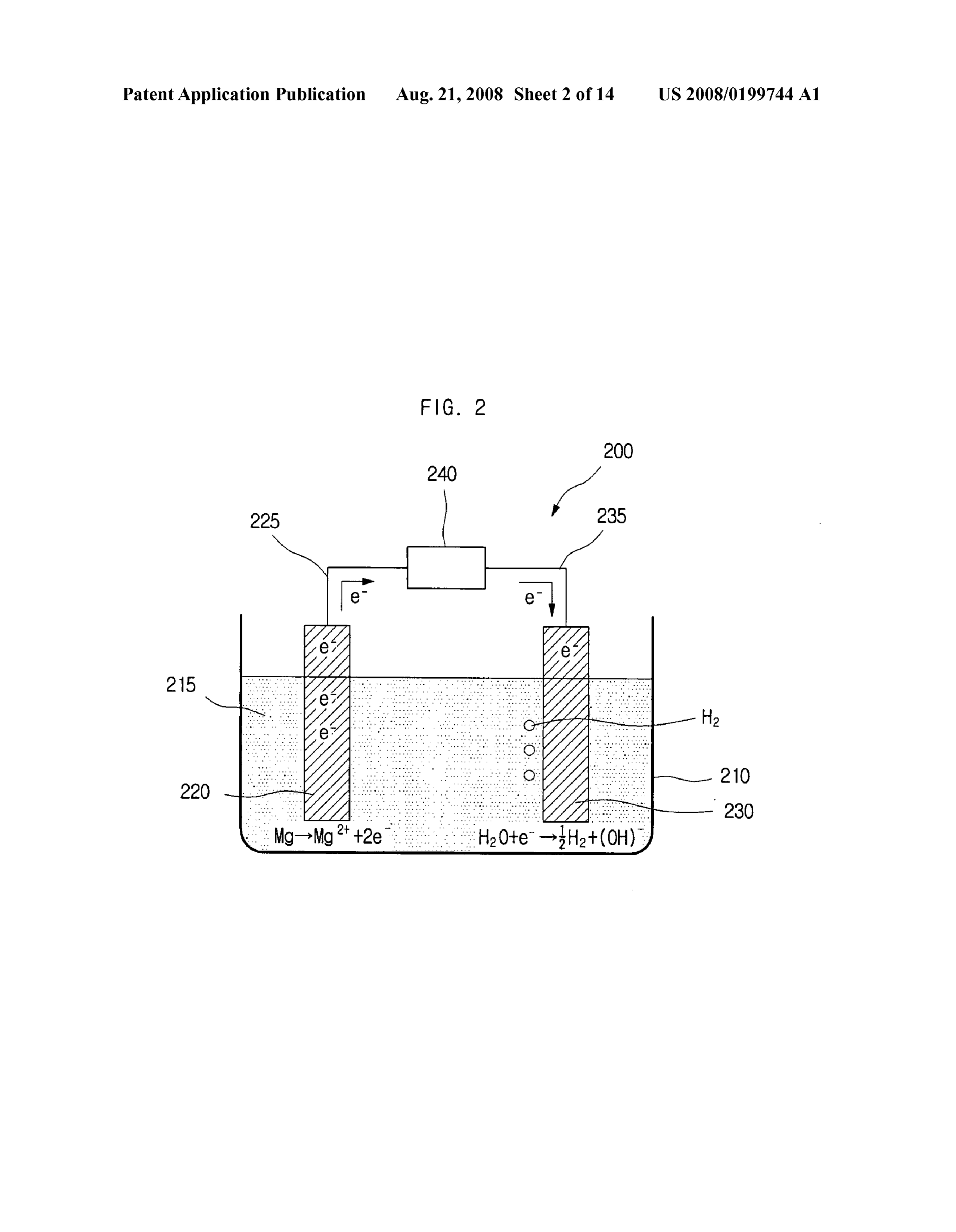
0037. These and other features, aspects and advantages of 0053 Terms such as “first and “second can be used in the present invention will become better understood with describing various elements, but the above elements shall not be restricted to the above terms. The above terms are used regard to the following description, appended claims and only to distinguish one element from the other. For instance, accompanying drawings where: the first element can be named the second element, and vice 0038 FIG. 1 illustrates an operational architecture of a Versa, without departing the scope of claims of the present fuel cell; invention. The term “and/or shall include the combination of 0039 FIG. 2 shows a sectional view of a hydrogen gener a plurality of listed items or any of the plurality of listed items. ating apparatus in accordance with an embodiment of the 0054 When one element is described as being “con present invention; nected' or “accessed to another element, it shall be con 0040 FIG.3 is a graph showing how the amount of electric Strued as being connected or accessed to the other element directly but also as possibly having another element in current between a first electrode and a second electrode and between. On the other hand, if one element is described as the amount of generated hydrogen are related in a hydrogen being “directly connected” or “directly accessed to another generating apparatus in accordance with an embodiment of element, it shall be construed that there is no other element in the present invention; between.
Page 19
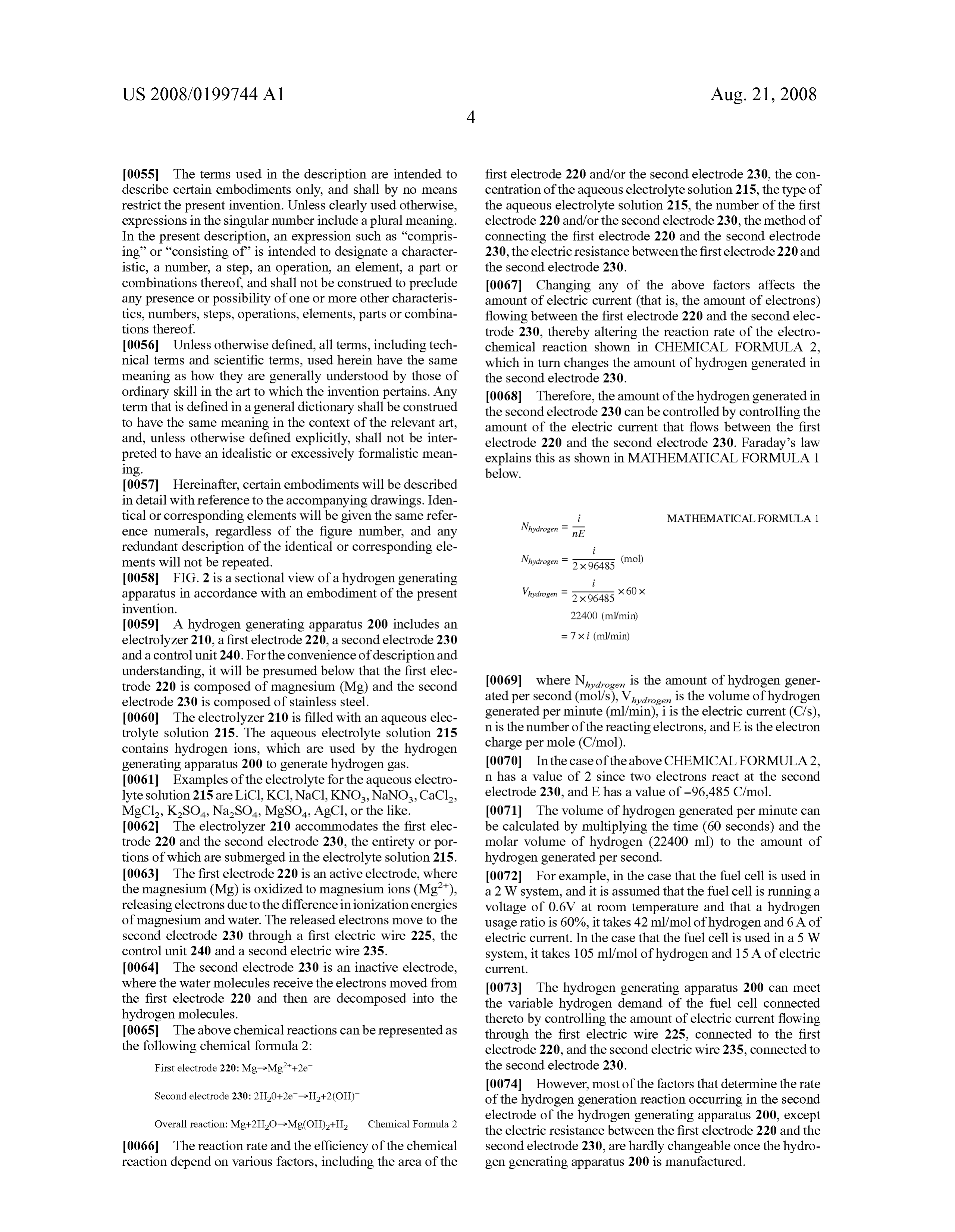
US 2008/O 199744 A1 Aug. 21, 2008
0055. The terms used in the description are intended to first electrode 220 and/or the second electrode 230, the con describe certain embodiments only, and shall by no means centration of the aqueous electrolyte solution 215, the type of restrict the present invention. Unless clearly used otherwise, the aqueous electrolyte solution 215, the number of the first expressions in the singular number include a plural meaning. electrode 220 and/or the second electrode 230, the method of In the present description, an expression Such as "compris connecting the first electrode 220 and the second electrode ing’ or “consisting of is intended to designate a character 230, the electric resistance between the first electrode 220 and istic, a number, a step, an operation, an element, a part or the second electrode 230.
combinations thereof, and shall not be construed to preclude 0067 Changing any of the above factors affects the any presence or possibility of one or more other characteris amount of electric current (that is, the amount of electrons) tics, numbers, steps, operations, elements, parts or combina flowing between the first electrode 220 and the second elec tions thereof. trode 230, thereby altering the reaction rate of the electro 0056. Unless otherwise defined, all terms, including tech chemical reaction shown in CHEMICAL FORMULA 2, nical terms and Scientific terms, used herein have the same which in turn changes the amount of hydrogen generated in meaning as how they are generally understood by those of the second electrode 230.
ordinary skill in the art to which the invention pertains. Any 0068. Therefore, the amount of the hydrogen generated in term that is defined in a general dictionary shall be construed the second electrode 230 can be controlled by controlling the to have the same meaning in the context of the relevant art, amount of the electric current that flows between the first and, unless otherwise defined explicitly, shall not be inter electrode 220 and the second electrode 230. Faraday's law preted to have an idealistic or excessively formalistic mean explains this as shown in MATHEMATICAL FORMULA 1 1ng. below.
0057. Hereinafter, certain embodiments will be described in detail with reference to the accompanying drawings. Iden tical or corresponding elements will be given the same refer i MATHEMATICAL FORMULA 1 ence numerals, regardless of the figure number, and any Nhydrogen = nE redundant description of the identical or corresponding ele ments will not be repeated. Nhydrogen = 2x 96485 (mol) 0058 FIG. 2 is a sectional view of a hydrogen generating i apparatus in accordance with an embodiment of the present Whydrogen = 2x 96485 x 60 x invention.
0059 A hydrogen generating apparatus 200 includes an electrolyzer 210, a first electrode 220, a second electrode 230 = 7Xi (ml/min) and a control unit 240. For the convenience of description and understanding, it will be presumed below that the first elec trode 220 is composed of magnesium (Mg) and the second I0069 where N, is the amount of hydrogen gener electrode 230 is composed of stainless steel. ated per second (mol/s), V, is the Volume of hydrogen 0060. The electrolyzer 210 is filled with an aqueous elec generated per minute (ml/min), i is the electric current (Cfs), trolyte solution 215. The aqueous electrolyte solution 215 n is the number of the reacting electrons, and E is the electron contains hydrogen ions, which are used by the hydrogen charge per mole (C/mol).
generating apparatus 200 to generate hydrogen gas. 0070. In the case of the above CHEMICAL FORMULA2, 0061 Examples of the electrolyte for the aqueous electro n has a value of 2 since two electrons react at the second lyte solution 215 are LiCl, KC1, NaCl, KNO, NaNO, CaCl, electrode 230, and E has a value of -96.485 C/mol. MgCl, KSO, NaSO, MgSO, AgCl, or the like. 0071. The volume of hydrogen generated per minute can 0062. The electrolyzer 210 accommodates the first elec be calculated by multiplying the time (60 seconds) and the trode 220 and the second electrode 230, the entirety or por molar volume of hydrogen (22400 ml) to the amount of tions of which are submerged in the electrolyte solution 215. hydrogen generated per second.
0063. The first electrode 220 is an active electrode, where 0072 For example, in the case that the fuel cell is used in the magnesium (Mg) is oxidized to magnesium ions (Mg"), a 2W system, and it is assumed that the fuel cell is running a releasing electrons due to the difference inionization energies Voltage of 0.6V at room temperature and that a hydrogen of magnesium and water. The released electrons move to the usage ratio is 60%, it takes 42 ml/mol of hydrogen and 6A of second electrode 230 through a first electric wire 225, the electric current. In the case that the fuel cell is used in a 5W control unit 240 and a second electric wire 235. system, it takes 105 ml/mol of hydrogen and 15 A of electric 0064. The second electrode 230 is an inactive electrode, Current.
where the water molecules receive the electrons moved from 0073. The hydrogen generating apparatus 200 can meet the first electrode 220 and then are decomposed into the the variable hydrogen demand of the fuel cell connected hydrogen molecules. thereto by controlling the amount of electric current flowing 0065. The above chemical reactions can be represented as through the first electric wire 225, connected to the first the following chemical formula 2: electrode 220, and the second electric wire 235, connected to First electrode 220:Mg->Mg2+2e. the second electrode 230.
0074. However, most of the factors that determine the rate
Second electrode 230: 2H20+2e->H+2(OH) of the hydrogen generation reaction occurring in the second Overall reaction: Mg+2H2O->Mg(OH)2+H2 Chemical Formula 2 electrode of the hydrogen generating apparatus 200, except the electric resistance between the first electrode 220 and the 0066. The reaction rate and the efficiency of the chemical second electrode 230, are hardly changeable once the hydro reaction depend on various factors, including the area of the gen generating apparatus 200 is manufactured.
Page 20
US 2008/O 199744 A1 Aug. 21, 2008
0075. Therefore, the hydrogen generating apparatus 200 0092. The above conditions were used for every graph according to this embodiment of the present invention has the referred to in describing the present invention. control unit 240 disposed between the first electric wire 225 0093 FIG. 3 shows a greater flow rate of the hydrogen and the second electric wire 235, which connect the first than a theoretical value based on MATHEMATICAL FOR electrode 220 and the second electrode 230, in order to regu MULA1, due to an interaction of the three pairs of electrodes. late the electric resistance between the first electrode 220 and 0094. Nevertheless, it is verified from FIG.3 that the flow the second electrode 230. rate of hydrogen is correlated with the amount of electric 0076. Thus, the hydrogen generating apparatus 200 con current between the first electrode 220 and the second elec trols the electric resistance between the first electrode 220 and trode 230. Also, the graph shows an almost linear relation the second electrode 230, that is, the amount of the electric between the flow-rate and the amount of the electric current, current flowing therebetween, thereby generating as much which agrees with the MATHEMATICAL FORMULA 1. hydrogen as needed by the fuel cell. (0095 FIG. 4 is a block diagram of the control unit 240 of 0077. The first electrode 220 can be also composed of a the hydrogen generating apparatus in accordance with an metal having a relatively high ionization tendency, such as embodiment of the present invention. iron (Fe), aluminum (Al), Zinc (Zn), or the like. The second 0096. The control unit 240 comprises a flow rate meter electrode 230 can be also composed of a metal having a 410, a Switch controller 420 and a switch 430. relatively low ionization tendency compared to the metal of 0097. The flow rate meter 410 measures the amount of the first electrode 220, such as platinum (Pt), aluminum (Al), hydrogen, in units of flow rate, generated from the second copper (Cu), gold (Au), silver (Ag), iron (Fe), or the like. electrode 230 of the hydrogen generating apparatus. As 0078. The control unit 240 controls a transfer rate, that is, described above, in order to use the hydrogen generating the amount of electric current, at which electrons generated in apparatus 200 in accordance with the present invention by the first electrode 220 are transferred to the second electrode coupling to a fuel cell, a certain amount of hydrogen genera 230. tion, not a total quantity of hydrogen generation, should be 007.9 The control unit 240 receives information on the maintained, and thus it is required that the amount of hydro amount of power or hydrogen demanded for the fuel cell and, gen generation be measured in units of ml/min. Of course, it according to the information, controls the amount of electrons is possible to use other measurement units as long as the unit flowing from the first electrode 220 to the second electrode is capable of measuring the flow rate. 230. If the demanded amount of power or hydrogen is large, (0098. The switch controller 420 is inputted with a set the control unit 240 increases the amount of electrons, and the value, which is related to the amount of hydrogen generation. control unit 240 reduces the amount of the electrons if the The hydrogen generating apparatus 200 is disposed with a demanded amount of power or hydrogen is Small. separate input unit (not shown), through which the set value 0080. The hydrogen generating apparatus 200 can receive can be inputted by the user. The required amount of output the information on the amount of the power or the hydrogen (i.e. electric power, Voltage, current, impedance, or a combi demanded for the fuel cell from the fuel cell combined with nation thereof) or hydrogen generation may be inputted by a the hydrogen generating apparatus 200 or from a user, who fuel cell that is coupled to the hydrogen generating apparatus inputs the information through a separate input unit. 200. In the latter case, the fuel cell may be separately 0081. The hydrogen generating apparatus of the present equipped with a hydrogen requiring unit for inputting the invention can have a plurality of the first electrodes 220 amount of output or hydrogen generation that is needed by the and/or the second electrodes 230. In the case that a plural hydrogen generating apparatus 200. number of the first electrode 220 and/or the second electrode (0099. The switch controller 420 compares the inputted set 230 are disposed, it can take a shorter time to generate the value with the amount of hydrogen generation measured by demanded amount of hydrogen since the hydrogen generat the flow rate meter 410. If the amount of generated hydrogen ing apparatus 200 can generate more hydrogen per unit time. is smaller than the set value, the switch 430 is controlled to 0082 FIG.3 is a graph showing how the amount of electric increase the amount of hydrogen generation, and if the current flowing between the first electrode 220 and the second amount of generated hydrogen is greater than the set value, electrode 230 is related to the volume of hydrogen generated the switch 430 is controlled to reduce the amount of hydrogen on the second electrode 230. Here, it should be noted that the generation. It is assumed that the switch 430 is controlled by Volume of hydrogen is shown in flow-rate measured per a switch control signal such that the switch controller 420 can minute, because not the total Volume of generated hydrogen turn the Switch 430 on or off.
but the flow-rate of hydrogen is significant to a fuel cell. 0100. The switch is disposed between the first electrode 0083. An experiment for FIG. 3 was conducted under the 220 and the second electrode 230. Electrons generated in the first electrode 220 is transferred to the second electrode 230 if following conditions:
0084 First electrode 220: Magnesium (Mg) the switch 430 is turned on, and the electrons generated in the first electrode 220 is not transferred to the second electrode 0085. Second electrode 230: Stainless steel 230 if the Switch 430 is turned off. 0.086 Distance between the electrodes: 3 mm 0101 That is, the control unit 240 controls the amount of 0087 Ingredients and concentration of electrolyte: 30 wt hydrogen generation, using the Switch 430 to control whether % KC1 the electrons are to be transferred from the first electrode 220 0088. Number of the electrodes: Magnesium 3 each, to the second electrode 230.
Stainless steel 3 each 0102 FIG. 5 is a block diagram of the control unit 240 of 0089 Electrode connecting method: Serial the hydrogen generating apparatus in accordance with 0090 Volume of aqueous electrolyte solution: 60 cc (ex another embodiment of the present invention. cessive condition) 0103) The control unit 240 includes an output meter 510, a 0091 Size of the electrode: 24mmx85mmx1 mm switch controller 420 and a switch 430. Here, the switch
Page 21
US 2008/O 199744 A1 Aug. 21, 2008
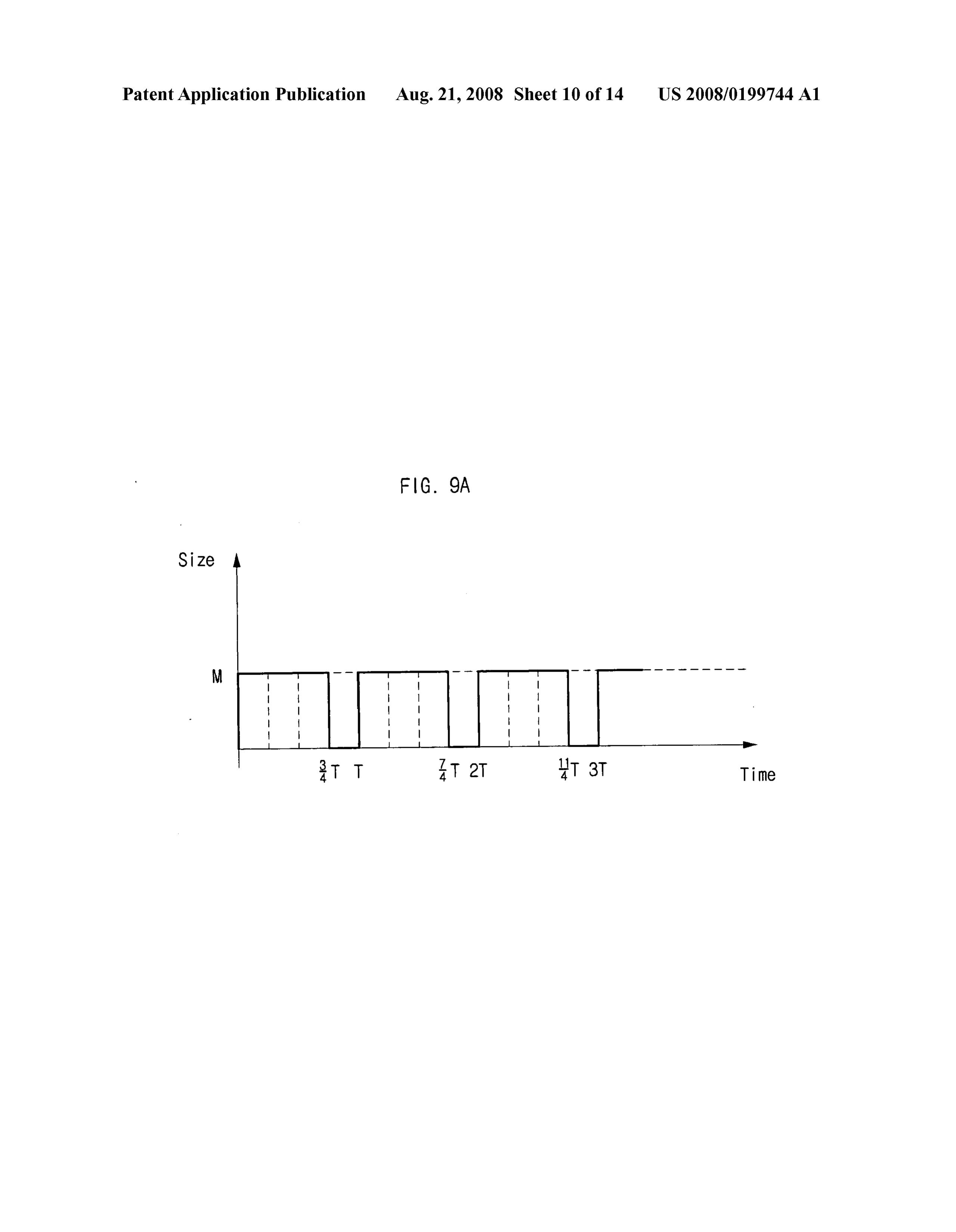
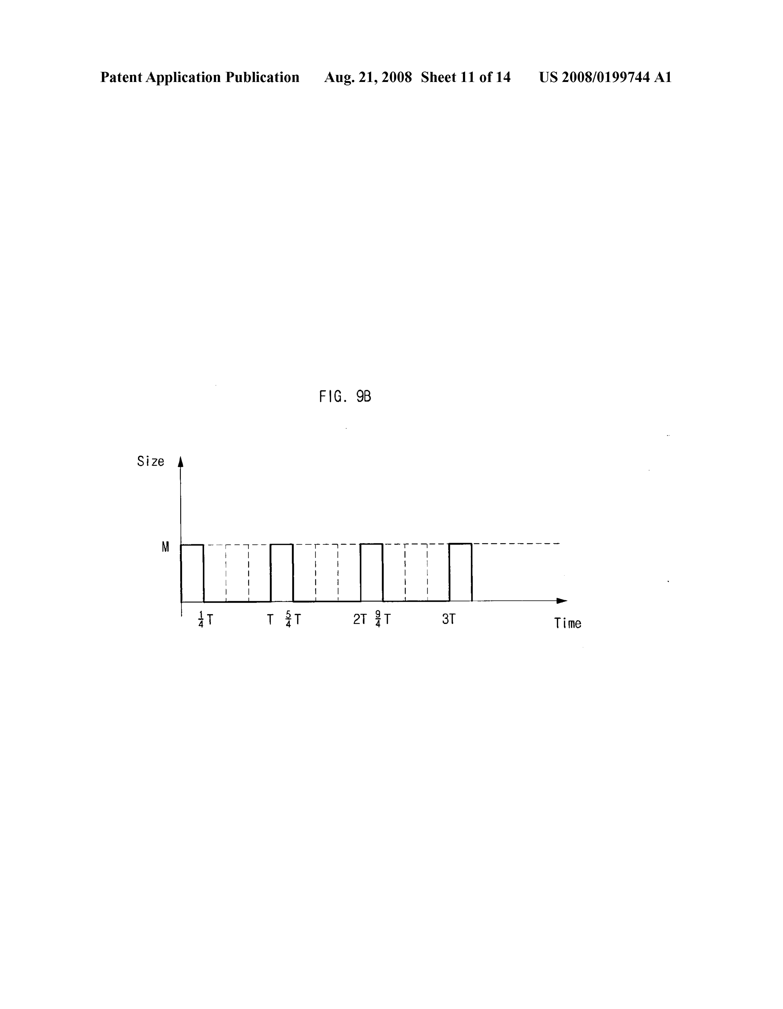
controller 420 and the switch 430 function the same way as 0113. The switch control signal inputted to the switch 430 described earlier with reference to FIG. 4, and thus their has a duty ratio (e.g., 50% in the case of FIGS. 7a and 7b), and description will be omitted. thus the switch 430 is turned on and off for the same duration 0104. The output meter 510 is connected to the fuel cell within one cycle.
100 to measure an output of the fuel cell 100. Here, the output 0114 Referring to FIG. 8, when the duty ratio of the refers to, for example, the amount of electric power, Voltage, switch 430 is controlled such that 42 ml/min of hydrogen is current, impedance or a combination thereof of the fuel cell generated for a fuel cell that requires 2 W of electric power, 100 that receives hydrogen, which is generated from the there is fluctuation in the amount of hydrogen generation hydrogen generating apparatus 200. The below description according to the on/off frequency. The temperature 810 of the will focus on electric power as the output of the fuel cell. hydrogen generating apparatus 200 increases steadily but 0105. As described above, a certain amount of hydrogen stays below 80 generation during certain duration, not a total amount of 0115 The amount of hydrogen generation 820 is close to hydrogen generation, has to be maintained in order to use the 42 ml/min. When the on/off frequency is relatively small (i.e., hydrogen generating apparatus 200 in accordance with an a large cycle) as in FIG.7a, the fluctuation is strong, as shown embodiment of the present invention by coupling with the in boxes represented by 840. When the on/off frequency is fuel cell. Therefore, the amount of electric power of the fuel relatively large (i.e., a small cycle) as in FIG.7b, the fluctua cell 100 based on the amount of hydrogen generation is mea tion is weak, as shown in boxes represented by 850. sured in units of watt (W). Ofcourse, it is possible to use other 0116. Therefore, for the same duty ratio, a relatively larger units as long as the amount of electric power can be measured. on/off frequency of the Switch control signal causes less fluc 0106 Although the below description focuses on the con tuation and is easier to maintain the desired amount of hydro trol with the Switch 430 of a hydrogen generating apparatus gen generation.
that is equipped with the flow rate meter 410 shown in FIG.4, 0117 FIG. 9a is a first example of duty ratios of the switch it shall be evident that the same description applies to a of a hydrogen generating apparatus in accordance with an hydrogen generating apparatus 200 equipped with the output embodiment of the present invention, and FIG.9b is a second meter 510 shown in FIG. 5. example of duty ratios of the Switch of a hydrogen generating 0107 FIG. 6 is a graph of the amount of hydrogen genera apparatus in accordance with an embodiment of the present tion, expressed in units of flow rate, when the switch 430 is invention. FIG. 10 shows how the quantity of hydrogen gen turned on. eration is related to time when the duty ratio of the switch is 0108). If the switch 430 stays on for a while, the reaction controlled.
becomes very fast at the beginning, raising the temperature 0118 Referring to FIG. 9a, the switch control signal has a and rapidly increasing the amount of hydrogen generation as cycle of T and a duty ratio of 75%, that is, the switch control much as 100 ml/min. Then, the amount of hydrogen genera signal is high for 3/4 T and low for 4 T. tion quickly drops due to the reduction of water in the aqueous 0119 Referring to FIG.9b, the switch control signal has a electrolyte solution and the metal composing the first elec cycle of T, which is the same as that of FIG. 9a, and a duty trode 220. ratio of 25%, that is, the switch control signal is high for 4T 0109. In such a case, it becomes difficult to control the and low for 3/4 T.
amount of hydrogen generation, and thus the amount of 0.120. By controlling the duty ratio of the switch control hydrogen generation is controlled to a desired flow rate by signal that is inputted to the switch 430, it becomes possible having the switch controller 420 control the turning on/off of to control the amount of hydrogen generation per time that is the switch 430 such that the switch 430 has a certain duty ratio generated in the hydrogen generating apparatus 200. and/or on/off frequency. This will be further described with I0121 Referring to FIG. 10, the amount of hydrogen gen reference to FIG. 7a. eration is left to increase naturally at the beginning (refer to 0110 FIG. 7a is a first example of the on/off frequency of the portion of graph represented by 1020), and then the switch the Switch of a hydrogen generating apparatus in accordance controller 420 controls the on and off of the switch 430 to with an embodiment of the present invention, and FIG.7b is generate 42 ml/min (1021), 10 ml/min (1022), 42 ml/min a second example of the on/off frequency of the switch of a (1023), 20 ml/min (1024) and 30 ml/min (1025) of hydrogen. hydrogen generating apparatus in accordance with an I0122) When the amount of hydrogen generation is embodiment of the present invention. Furthermore, FIG. 8 adjusted from 42 ml/min (1021) to 10 ml/min (1022), the ratio shows how the amount of hydrogen generation is related to of off-time of the switch control signal within one cycle is time when the on/off frequency of the switch is controlled. It increased, that is, the duty ratio is gradually decreased. Then, will be assumed hereinafter that the Switch 430 is turned on by steadily maintaining the duty ratio when the flow rate when the size of an inputted Switch control signal is M (i.e., meter 410 reads 10 ml/min of hydrogen generation, the high) and turned off when the size of an inputted switch amount of hydrogen generation is kept at 10 ml/min. control signal is 0 (i.e., low). I0123. When the amount of hydrogen generation is 0111 Referring to FIG. 7a, the switch control signal adjusted from 10 ml/min (1022) to 42 ml/min (1023), the ratio inputted to the switch 430 has a frequency of T and a duty of on-time of the Switch control signal within one cycle is ratio of 50%. In other words, the switch control signal input increased, that is, the duty ratio is gradually increased. Then, ted to the switch 430 is high for '/2T and low for /2 T. by steadily maintaining the duty ratio when the flow rate 0112 Referring to FIG. 7b, on the other hand, the switch meter 410 reads 42 ml/min of hydrogen generation, the control signal inputted to the switch 430 has a frequency of 4 amount of hydrogen generation is kept at 42 ml/min. T and a duty ratio of 50%. In other words, the switch control 0.124. By repeatedly performing the above adjustment of signal inputted to the switch 430 is high for /&T and low for duty ratio, the switch controller 420 can adjust the amount of /8 T. hydrogen generation according to changing set values.
Page 22
US 2008/O 199744 A1 Aug. 21, 2008
0.125. As described with reference to FIGS. 7a to 8, it is reduced in step S1134a. If the amount of hydrogen generation possible to control the fluctuation in the amount of hydrogen is equal to the set value (A=B), the current duty ratio of the generation by changing the on/off frequency of the Switch Switch control signal is maintained, in step S1136.a. 430 in case a certain amount of hydrogen generation is main 0.136. In case the upper limit and the lower limit are input tained. ted in step S1120b, the amount of hydrogen generation (A), 0126. Moreover, the amount of hydrogen generation mea the upper limit (B1) and the lower limit (B2) are compared in sured in units of flow rate in FIGS. 6 to 10 may be the amount step 1130b. If the amount of hydrogen generation is smaller of electric power outputted from the fuel cell 100 in a hydro than the lower limit (A-B2), the duty ratio of the switch gen generating apparatus 200 shown in FIG. 5. For example, control signal is increased in step 1132b, and if the amount of the flow rate of 42 ml/min shown in FIGS. 6 to 10 can hydrogen generation is greater than the upper limit (AZB1). correspond to 2 W, depending on the operation condition of the duty ratio of the Switch control signal is reduced in step the fuel cell 100. S1134b. If the amount of hydrogen generation is between the 0127. In other words, the earlier-measured amounts of upper limit and the lower limit (B2=A=B1), the current duty hydrogen generation correspond to the output of the fuel cell ratio of the switch control signal is maintained in S1136b. (i.e., amount of electric power) that is measured by the output I0137. By repeating steps S1120 to S1136a or S1136b, the meter 510 of the hydrogen generating apparatus 200. The hydrogen generating apparatus 200 can generate the amount amount of hydrogen generation to be controlled through the of hydrogen according to the inputted set value. on/off control of the switch corresponds to the output of the 0.138 FIG. 12 is a flowchart showing a method of control fuel cell, that is, the amount of electric power. ling the amount of hydrogen generation in a hydrogen gen 0128. The Switch of the hydrogen generating apparatus in erating apparatus in accordance with another embodiment of accordance with an embodiment of the present invention can the present invention. The hydrogen generating apparatus of be made of an MOS (metal-oxide semiconductor) transistor. FIG. 12 is illustrated in FIG.S.
0129. The switch controller of the hydrogen generating 0.139. The switch controller 420 of the hydrogen generat apparatus in accordance with an embodiment of the present ing apparatus 200 turns on the switch 430 and generates invention can use a power circuit of the fuel cell and be hydrogen over a certain threshold of flow rate, in the step included in a control unit of a fuel cell generating system. In represented by S1200.
other words, by including the switch controller in the control 0140. The output meter 510 measures the output (e.g., unit of a fuel cell generating system, the Switch controller and amount of electric power) of the fuel cell, in the step repre the control unit of the fuel cell generating system can be made sented by S1210, and the Switch controller 420 compares the into one chip. output of the fuel cell, measured by the output meter 510, and 0130. Moreover, the hydrogen generating apparatus of the the inputted set value in S1220. Here, the inputted set value present invention can compose a fuel cell generating system can be one value, as shown in S1220a, or have an upper limit by being connected to a fuel cell. The fuel cell generating and a lower limit with a range, as shown in S1220b. system includes a hydrogen generating apparatus that is pos 0.141. The switch controller 420 generates a switch control sible to control the amount of hydrogen generation and a fuel signal for controlling the on/off of the switch 430 according to cell that generates electricity by being supplied with hydro the set value and applies the Switch control signal to the gen from the hydrogen generating apparatus. Switch 430.
0131 FIG. 11 is a flowchart showing a method of control 0142. If one set value is inputted, as shown in S1220a, the ling the amount of hydrogen generation in a hydrogen gen output of the fuel cell (A) and the set value (B) are compared erating apparatus in accordance with an embodiment of the in S1230a. In case the output of the fuel cell is smaller than the present invention. The hydrogen generatingapparatus of FIG. set value (A-B), the duty ratio of the switch control signal is 11 is illustrated in FIG. 4. increased in S1232a, and if the output of the fuel cell is greater 0132) The switch controller 420 of the hydrogen generat than the set value (AaB), the duty ratio of the switch control ing apparatus 200 turns on the switch 430 and generates signal is reduced in S1234a. If the output of the fuel cell is hydrogen over a certain threshold of flow rate, in the step equal to the set value (A=B), the current duty ratio of the represented by S1100. switch control signal is maintained in S1236a. 0133. In step S1110, the flow rate meter 410 measures the 0143. In case the upper limit and the lower limit are input amount of hydrogen generation, and in step S1120 the Switch ted in step S1220b, the amount of hydrogen generation (A), controller 420 compares the amount of hydrogen generation, the upper limit (B1) and the lower limit (B2) are compared in measured by the flow rate meter 410, with an inputted set step 1230b. If the amount of hydrogen generation is smaller value. Here, the inputted set value can be one value, as shown than the lower limit (A-B2), the duty ratio of the switch in step S1120a, or have an upper limit and a lower limit with control signal is increased in step 1232b, and if the amount of a range, as shown in step 1120b. hydrogen generation is greater than the upper limit (AZB1). 0134. The switch controller 420 generates a switch control the duty ratio of the Switch control signal is reduced in step signal for controlling the on/off of the Switch according to the S1234b. If the amount of hydrogen generation is between the set value and applies the Switch control signal to the Switch upper limit and the lower limit (B2=A=B1), the current duty 430. ratio of the switch control signal is maintained in S1236b. 0135) If one set value is inputted, as shown in step S1120a, 0144. By repeating steps S2120 to S1236a or S1236b, the the amount of hydrogen generation (A) and the set value (B) hydrogen generating apparatus 200 can generate the amount are compared in step S1130a. In case the amount of hydrogen of hydrogen according to the inputted set value. generation is smaller than the set value (A-B), the duty ratio 0145. In the above method of controlling the amount of of the switch control signal is increased in step S1132a, and if hydrogen generation, steps S1120 to S1136a or 1136b, or the amount of hydrogen generation is greater than the set steps S1220 to S1236a or 1236b, can be written in a computer value (AaB), the duty ratio of the switch control signal is program. Codes and code segments, composing the program,
Page 23
US 2008/O 199744 A1 Aug. 21, 2008
can be easily realized by a computer programmer skilled in 9. The apparatus of claim 6, in which the set value com the art. Moreover, the program is stored in a computer read prises an upper limit and a lower limit, able medium, and realizes the method of controlling the and the switch controller compares the set value with the amount of hydrogen generation by being read and run by a measured amount of hydrogen generation, and increases computer. The computer readable medium described above the duty ratio if the amount of hydrogen generation is includes a magnetic recording medium, an optical recording smaller than the lower limit, reduces the duty ratio if the medium and a carrier wave medium. amount of hydrogen generation is greater than the upper 0146 The drawings and detailed description are only limit, and maintains the duty ratio if the amount of examples of the present invention, serve only for describing hydrogen generation is between the lower limit and the the present invention and by no means limit or restrict the upper limit.
spirit and scope of the present invention. Thus, any person of 10. A fuel cell power generation system comprising: ordinary skill in the art shall understand that a large number of a hydrogen generating apparatus, controlling an amount of permutations and other equivalent embodiments are possible. hydrogen generation by controlling an on/off status of a The true scope of the present invention must be defined only Switch connected between electrodes; and by the ideas of the appended claims. a fuel cell, being Supplied with hydrogen generated by the What is claimed is: hydrogen generating apparatus and producing a direct 1. A hydrogen generating apparatus comprising: current by converting chemical energy of the hydrogen an electrolyzer, filled with an aqueous electrolyte Solution to electrical energy.
containing hydrogen ions; 11. The system of claim 10, in which the hydrogen gener a first electrode, accommodated in the electrolyzer, Sub ating apparatus comprises:
merged in the aqueous electrolyte solution, and gener an electrolyzer, filled with an aqueous electrolyte Solution ating electrons; containing hydrogen ions;
a second electrode, accommodated in the electrolyzer, Sub a first electrode, accommodated in the electrolyzer, Sub merged in the aqueous electrolyte solution, receiving the merged in the aqueous electrolyte solution, and gener electrons to generate hydrogen; ating electrons;
a switch, located between the first electrode and the second a second electrode, accommodated in the electrolyzer, Sub electrode: merged in the aqueous electrolyte solution, receiving the a flow rate meter, measuring an amount of hydrogen gen electrons to generate hydrogen; eration in the second electrode; and a switch, located between the first electrode and the second a Switch controller, receiving a set value, comparing the electrode:
amount of hydrogen generation measured by the flow a meter, measuring an amount of hydrogen generation oran rate meter with the set value, and controlling an on/off output of a fuel cell; and status of the switch. a Switch controller, receiving a set value, comparing the 2. The apparatus of claim 1, in which the switch controller amount of hydrogen generation or the output of the fuel is inputted with the set value directly from a user through an cell measured by the meter with the set value, and con input unit. trolling an on/off status of the switch. 3. The apparatus of claim 1, in which the hydrogen gener 12. The system of claim 11, in which the switch controller ating apparatus is coupled to a fuel cell and Supplies hydro is inputted with the set value directly from a user through an gen, input unit.
and the switch controller is inputted with the set value in 13. The system of claim 11, in which the hydrogen gener accordance with an amount of hydrogen generation that ating apparatus is coupled to the fuel cell and Supplies hydro is required by the fuel cell. gen, 4. The apparatus of claim 1, in which a metal forming the and the switch controller is inputted with the set value in first electrode has a higher ionization tendency than a metal accordance with an amount of electric power, Voltage, forming the second electrode. current, impedance or a combination thereof or an 5. The apparatus of claim 1, in which the flow rate meter amount of hydrogen generation that is required by the measures the amount of hydrogen generation in units of flow fuel cell.
rate. 14. The system of claim 11, in which a metal forming the 6. The apparatus of claim 1, in which the switch controller first electrode has a higher ionization tendency than a metal generates and outputs a Switch control signal turning the forming the second electrode.
switch on and off, 15. The system of claim 11, in which the switch controller and the Switch controller determines an on/off ratio of the generates and outputs a Switch control signal turning the switch within one cycle by varying a duty ratio of the switch on and off,
Switch control signal. and the switch controller determines an on/off ratio of the 7. The apparatus of claim 6, in which the switch controller switch within one cycle by varying a duty ratio of the controls a fluctuation in the amount of hydrogen generation Switch control signal.
by varying an on/off frequency of the Switch control signal. 16. The system of claim 15, in which the meter is a flow rate 8. The apparatus of claim 6, in which the switch controller meter that measures the amount of hydrogen generated in the compares the set value with the measured amount of hydro second electrode in units of flowrate. gen generation, and increases the duty ratio if the amount of 17. The system of claim 16, in which the switch controller hydrogen generation is Smaller than the set value, reduces the controls a fluctuation in the amount of hydrogen generation duty ratio if the amount of hydrogen generation is greater than by varying an on/off frequency of the Switch control signal. the set value, and maintains the duty ratio if the amount of 18. The system of claim 16, in which the switch controller hydrogen generation is equal to the set value. compares the set value with the measured amount of hydro
Page 24
US 2008/O 199744 A1 Aug. 21, 2008
gen generation, and increases the duty ratio if the amount of value, reducing the duty ratio of the Switch control signal hydrogen generation is Smaller than the set value, reduces the if the amount of hydrogen generation is greater than the duty ratio if the amount of hydrogen generation is greater than upper value, and maintaining the duty ratio of the Switch the set value, and maintains the duty ratio if the amount of control signal if the amount of hydrogen generation is hydrogen generation is equal to the set value. between the lower value and the upper value, in which 19. The system of claim 16, in which the set value com the switch control signal controls the on/off status of the prises an upper limit and a lower limit, switch within one cycle in accordance with the duty and the switch controller compares the set value with the ratio.
measured amount of hydrogen generation, and increases 26. A method of controlling an amount of hydrogen gen the duty ratio if the amount of hydrogen generation is eration in a hydrogen generating apparatus controlling an smaller than the lower limit, reduces the duty ratio if the amount of hydrogen generation by controlling an on/off sta amount of hydrogen generation is greater than the upper tus of a switch that is connected to a fuel cell and located limit, and maintains the duty ratio if the amount of between electrodes, the method comprising: hydrogen generation is between the lower limit and the being inputted with a set value;
upper limit. comparing an output of the fuel cell and the set value; and 20. The system of claim 15, in which the meter is an output increasing a duty ratio of a Switch control signal if the meter that measures an output of the fuel cell in units of watt output of the fuel cell is smaller than the set value, (W), volt (V), ampere (A), ohm (S2) or a combination thereof. reducing the duty ratio of the switch control signal if the 21. The system of claim 20, in which the switch controller output of the fuel cell is greater than the set value, and controls a fluctuation in the output of the fuel cell by varying maintaining the duty ratio of the Switch control signal if an on/off frequency of the Switch control signal. the output of the fuel cell is equal to the set value, in 22. The system of claim 20, in which the switch controller which the switch control signal controls the on/offstatus compares the set value with the measured output of the fuel of the switch within one cycle in accordance with the cell, and increases the duty ratio if the output of the fuel cell duty ratio.
is smaller than the set value, reduces the duty ratio if the 27. A method of controlling an amount of hydrogen gen output of the fuel cell is greater than the set value, and main eration in a hydrogen generating apparatus controlling an tains the duty ratio if the output of the fuel cell is equal to the amount of hydrogen generation by controlling an on/off sta set value.
tus of a switch that is connected to a fuel cell and located 23. The system of claim 20, in which the set value com between electrodes, the method comprising: prises an upper limit and a lower limit, and the switch controller compares the set value with the being inputted with an upper value and a lower value; measured output of the fuel cell, and increases the duty comparing a measured output of the fuel cell with the upper ratio if the output of the fuel cell is smaller than the lower value and the lower value; and limit, reduces the duty ratio if the output of the fuel cell increasing a duty ratio of a Switch control signal if the is greater than the upper limit, and maintains the duty output of the fuel cell is smaller than the lower value, ratio if the output of the fuel cell is between the lower reducing the duty ratio of the switch control signal if the limit and the upper limit. output of the fuel cell is greater than the upper value, and 24. A method of controlling an amount of hydrogen gen maintaining the duty ratio of the Switch control signal if eration in a hydrogen generating apparatus controlling an the output of the fuel cell is between the lower value and amount of hydrogen generation by controlling an on/off sta the upper value, in which the Switch control signal con tus of a switch located between electrodes, the method com trols the on/off status of the switch within one cycle in prising: accordance with the duty ratio. being inputted with a set value; 28. A recording medium having recorded a computer read comparing a measured amount of hydrogen generation and able program to control an amount of hydrogen generation in the set value; and a hydrogen generating apparatus controlling an amount of increasing a duty ratio of a Switch control signal if the hydrogen generation by controlling an on/off status of a amount of hydrogen generation is Smaller than the set switch located between electrodes, in which the recording value, reducing the duty ratio of the Switch control signal medium, being readable by a computer, having recorded a if the amount of hydrogen generation is greater than the program performing a method of controlling an amount of set value, and maintaining the duty ratio of the Switch hydrogen generation of claim 24.
control signal if the amount of hydrogen generation is 29. A recording medium having recorded a computer read equal to the set value, in which the Switch control signal able program to control an amount of hydrogen generation in controls the on/off status of the switch within one cycle a hydrogen generating apparatus controlling an amount of in accordance with the duty ratio. hydrogen generation by controlling an on/off status of a 25. A method of controlling an amount of hydrogen gen switch located between electrodes, in which the recording eration in a hydrogen generating apparatus controlling an medium, being readable by a computer, having recorded a amount of hydrogen generation by controlling an on/off sta program performing a method of controlling an amount of tus of a switch located between electrodes, the method com hydrogen generation of claim 25. prising: 30. A recording medium having recorded a computer read being inputted with an upper value and a lower value; able program to control an amount of hydrogen generation in comparing a measured amount of hydrogen generation a hydrogen generating apparatus controlling an amount of with the upper value and the lower value; and hydrogen generation by controlling an on/off status of a increasing a duty ratio of a Switch control signal if the switch located between electrodes, in which the recording amount of hydrogen generation is Smaller than the lower medium, being readable by a computer, having recorded a
Page 25
US 2008/O 199744 A1 Aug. 21, 2008
program performing a method of controlling an amount of switch located between electrodes, in which the recording hydrogen generation of claim 26. medium, being readable by a computer, having recorded a 31. A recording medium having recorded a computer read- program performing a method of controlling an amount of able program to control an amount of hydrogen generation in hydrogen generation of claim 27. a hydrogen generating apparatus controlling an amount of hydrogen generation by controlling an on/off status of a ck

Provenance
- Collection
- Patents citing this work
- Original assignee
- Samsung Electro Mechanics Co Ltd
- Pages
- 25
- Method
- pdftotext (the PDF's own text layer) + pdftoppm 300dpi page scans
- Patent office record
- patents.google.com →
- Source
- Google Patents citing-documents table
- Inventors
- Jae-Hyoung Gil; Jae-Hyuk Jang; Arunabha Kundu; Sung-han Kim; Kyoungsoo Chae; Samsung Electro Mechanics Co Ltd
- Published
- 2008-08-21
- Transcribed from
- patentimages.storage.googleapis.com →