patent · US3661424
Geothermal energy recovery from deep caverns in salt deposits by means of air flow
9 May 1972
Page 1 — bibliographic record
United States Patent (15) 3,661,424 Jacoby
54) GEOTHERMAL ENERGY RECOVERY
FROM DEEP CAVERNS IN SALT Primary Examiner-Ernest R. Purser
DEPOSITS BY MEANS OF AIR FLOW Attorney-Bean & Bean 72) inventor: Charles H. Jacoby, Dalton, Pa.
73) Assignee: International Salt Company, Clarks Sum mit, Pa. There is disclosed a method for abstracting geothermal heat from depths below ground that are inaccessible by commer (22 Filed: Oct. 20, 1970 cially practicable bore hole drilling techniques. More particu 21 Appl. No.: 82,231 larly, the invention is of a method for extracting heat from such an inaccessible source which comprises forming a cavern or reservoir at an accessible depth in a salt dome or spire 52 U.S. Cl............................................299/4, 611.5, 16571, which is in thermal communication with the otherwise inac 165/45 cessible heat source, and flowing air at comparatively low 5) Int. Cl...................................... E21b 43/28, F28d 21/00 speeds through the cavern in heat-exchange relation with the 58 Field of Search..................... 165/1, 45; 60/26; 166/254; wall surfaces thereof to absorb heat therefrom, and then flow 611.5; 299/2, 4, 5 ing it speedily through a relatively small (compared to the cavern volume) passageway to a point of use above ground, 56) References Cited whereby it retains a substantial proportion of the heat energy
UNITED STATES PATENTS
absorbed in the cavern. Such energy is utilized in any suitable manner, one such preferred use being for the evaporation of 3,348,883 10/1967 Jacoby et al...............................299/4 brine extracted from the cavern during preparation thereof or 3,386,768 6/1968 Jacoby et al.. obtained from neighboring salt deposits. 3,490,513 1/1970 Villanueva........................... 165/45 X 11 Claims, 4 Drawing Figures
Page 2
Drawing sheet — no readable text.
Page 3
Drawing sheet — no readable text.
Page 4
Drawing sheet — no readable text.
Page 5
Drawing sheet — no readable text.
Page 6
GEOTHERMAL ENERGY RECOVERY FROMDEEP
CAVERNS IN SALT DEPOSITS BY MEANS OF AIR FLOW The cavern will be at a depth close enough to the deep-seated heat source that the heat of the cavern walls will be promptly
BACKGROUND OF THE INVENTION replenished as withdrawn so as to maintain the heat extraction process at an acceptably high rate and temperature.
It is well known that the interior of the earth is extremely The volume of the cavern should be great compared to the hot, and because heat is an essential form of energy utilized in volume of the heated air exit passageway, which conveniently connection with almost all human activities as well as industri comprises abore hole extending from the cavern to a point at al operations, many suggestions have been made of ways to or near the earth's surface at which the heat of the gas or gases take advantage of this virtually unlimited supply of heat. 10 is utilized.
Because of our constantly increasing needs for energy and sufficientlySuch long a system will operate to maintain the gas (air) in the cavern so that it will be raised to a rapidly diminishing sources of fossil fuels, as well as our cur suitably high temperature, rently serious concern about air and water pollution caused by exit passageway so that heatandtransfer then to speed it through the and heat loss from the burning fuels to produce heat and electrical energy, it is vital that commercially feasible methods for extracting "clean' 15 gas to the earth through the passageway walls is minimized. For best operation, the volumes of the cavern and exit heat from this unlimited source be perfect.
Numerous other systems for such purposes have been previ passageway will be within certain ranges, as will the retention times of the gas in these places. In accordance with the present ously suggested but have met with only limited success, and invention, very large quantities of heat will be obtained from are of little if any commercial importance. For example, sup the geothermal source at very little expense after that incurred plies of hot gases or liquids issuing through fissures in the earth's surface are limited; extremely erratic and productively 20 forVarious the bore hole drilling and casing operations.
objects, details, constructions, operations, uses, unreliable; and are usually accompanied by inordinate equip and advantages of the invention will be apparent from the fol ment corrosion and "scaling' problems. None of these other lowing description, systems previously suggested possess the feasibility potentials drawing showing bytaken in conjunction with the illustrative of systems utilizing heat derived from inaccessibly deep 25 ing the methods of theway of example some systems for effect invention, in which drawing:
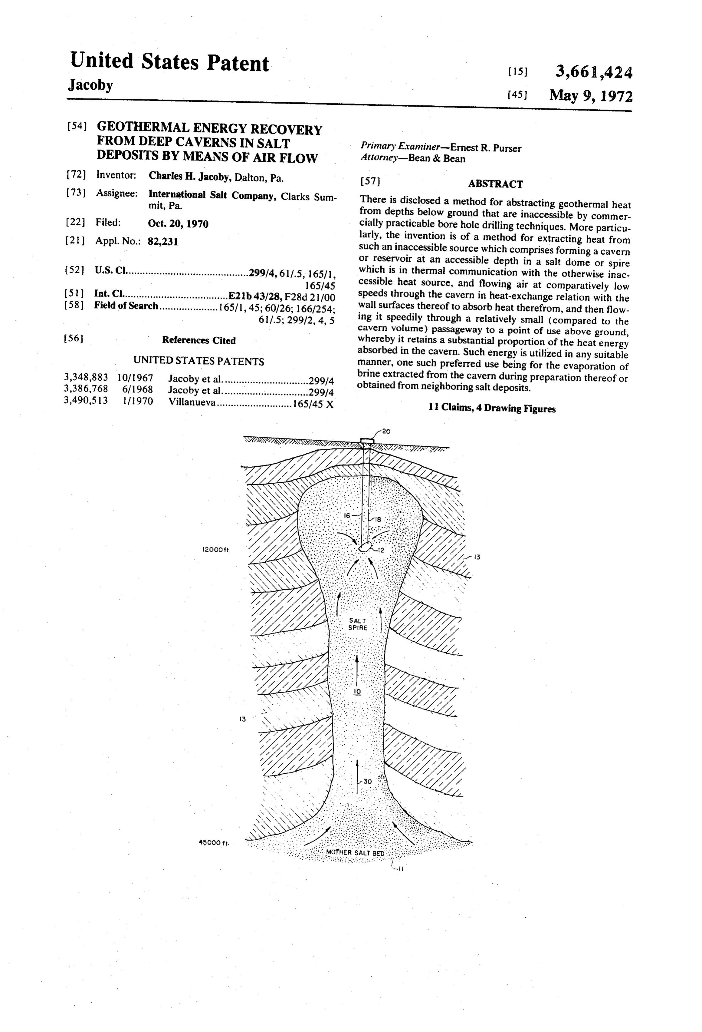
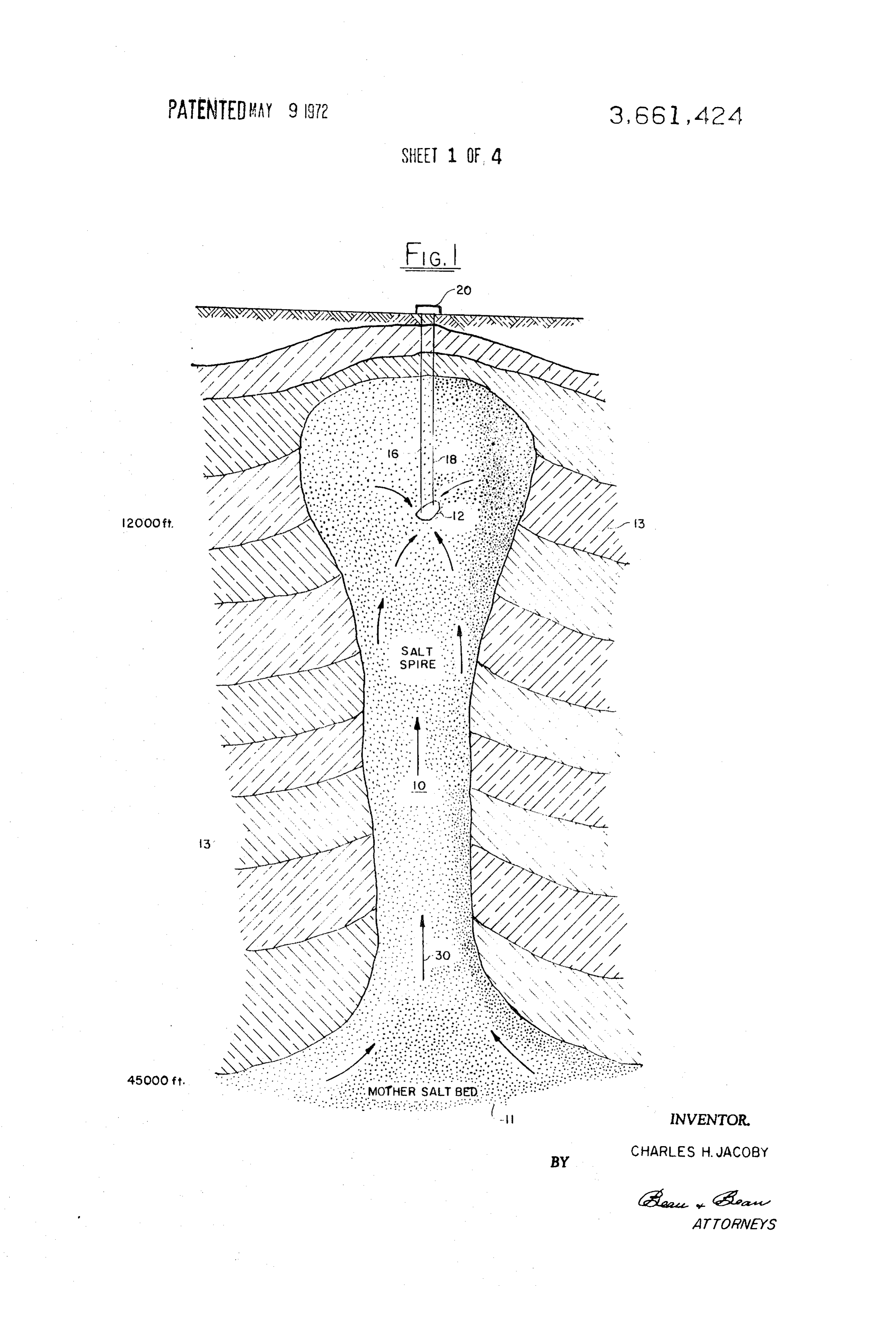
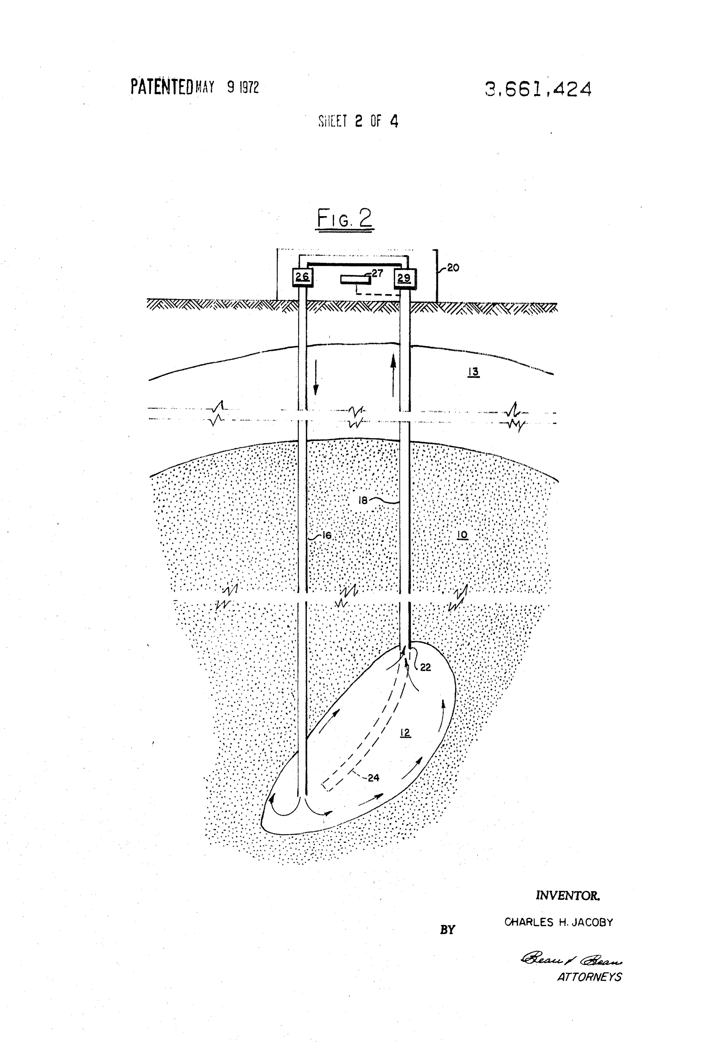
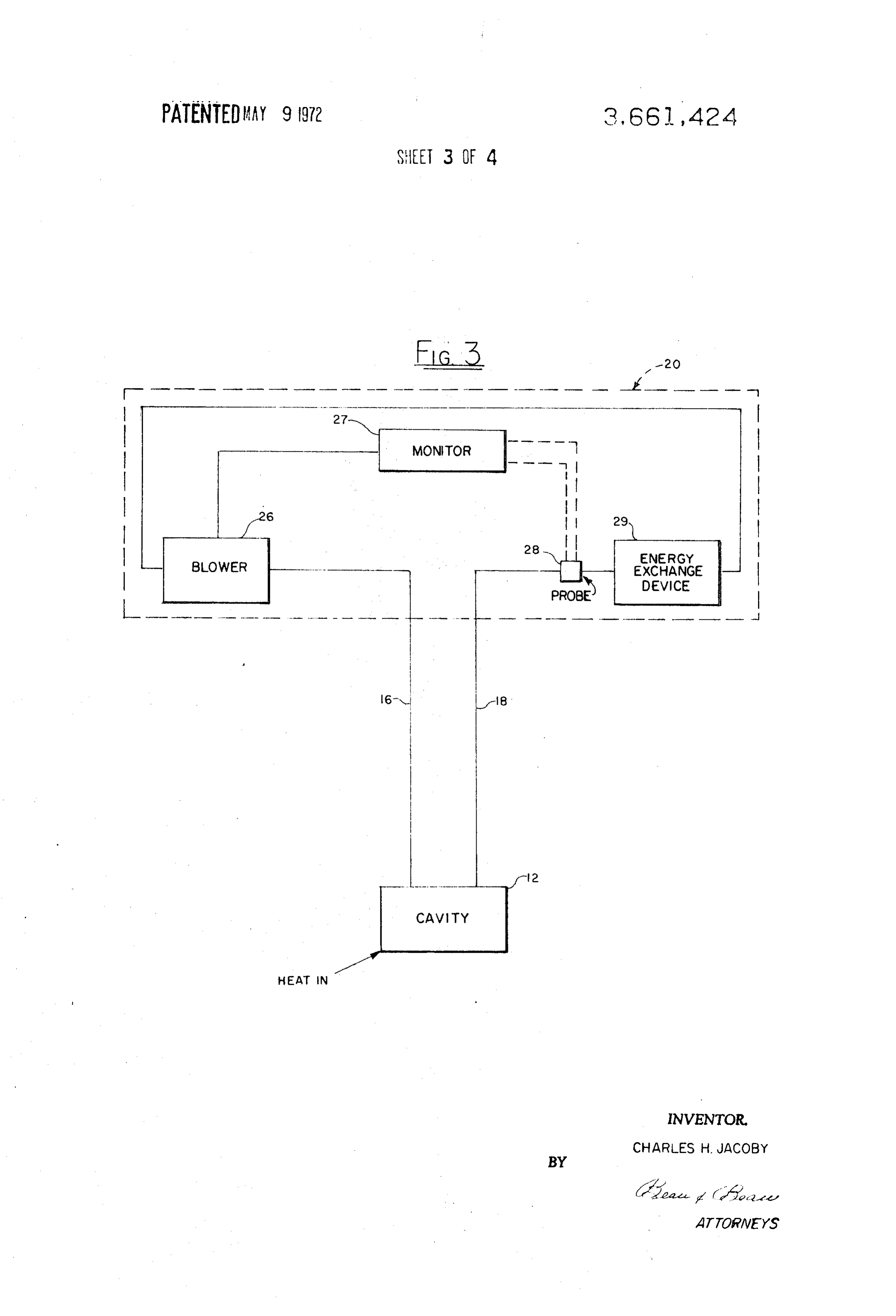
sources by conduction of such heat part-way towards the earth's surface through a highly heat conductive mineral spire THE DRAWING or dome-like geological structure, such heat being then ex tracted from the structure by forming at some accessible FIG. 1 is a vertical geologic sectional view illustrating a typi depth therein a heat-exchange cavern or "well" from which "- 30 cal system installed in a salt dome in accordance with the clean' heat may be extracted and piped to the earth's surface present invention;
without undesirable loss or contamination. Some such FIG. 2 is a fragmentary view on an enlarged scale of upper methods have been previously described in my pending U.S. and lower portions of the geologic section of FIG. 1, illustrat application Ser. Nos. 21,052; 21,051 and 21,082; all filed ing in more detail, but schematically, a form of heat extraction Mar. 19, 1970. 35 system and a form of aboveground heat utilization system; FIG. 3 is a flow diagram for the system of FIGS. 1 and 2; and
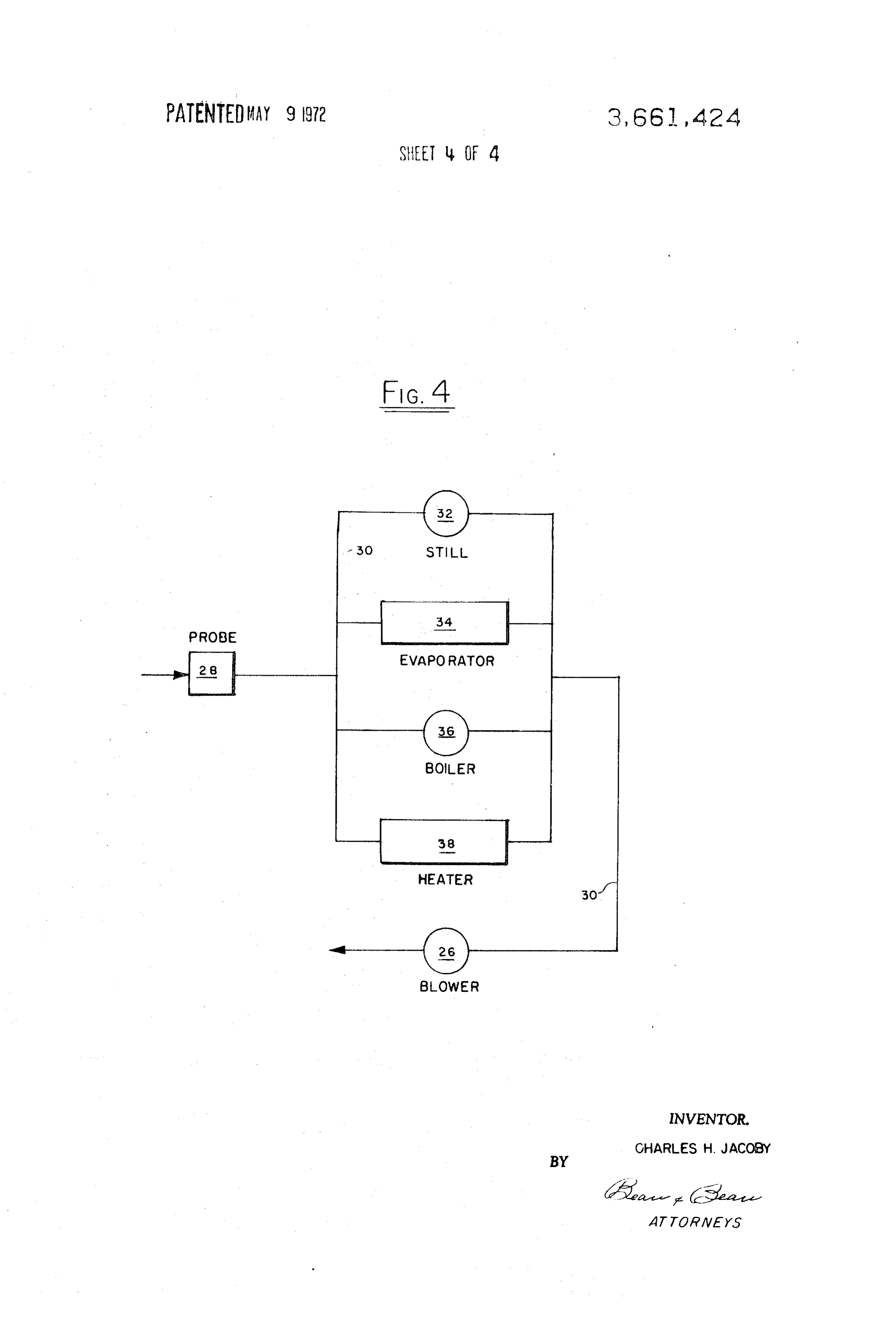
THE PRESENT INVENTION FIG. 4 is a schematic plan view of a plurality of energy In accordance with the present invention, geothermal heat exchange devices of different types such as may be employed is extracted from an otherwise inaccessible source by a 40 to utilize the heat energy of the air exiting from the cavern the velocity of the delivered heated air being caused by such plu method which comprises first locating a particular type of ral utilizations to be diminished to readily useful range. mineral formation; establishing a heat well or cavern at an ac cessible depth within said formation; flowing a comparatively DETAILED DESCRIPTION OF THE INVENTION cool gas throughout the heat well in heat exchange relation with the wall surfaces thereof; removing the heated gas from 45 in FIG. 1 is shown a geological phenomenon, known as a the heat well and transporting it to a point where its heat ener salt spire or dome 10 which had been formed by fluid or gy may be utilized. A suitable mineral formation is one of high plastic flow from a deepseated "mother bed' or the like as heat conductivity which extends vertically in thermal con shown at 11, and vertical intrusion of the spire or dome por tinuity from a deep-seated heat source at a depth which is in tion towards the earth surface through surrounding typical accessible by commercially practicable bore hole drilling SO geological strata 13 which are of lesser thermal conductivity. a techniques, to a higher level which is accessible by such heat reservoir cavity 12 is created in the dome by first drilling techniques. The heat well which is established within the for from an appropriate location at the earth's surface a pair of mation is at an accessible depth, and deep enough to assure bore holes as shown at 16 and 18, to a relatively great depth that heatenergy flowing from the source into the heat well will such as 12,000-15,000 feet as illustrated, after which a stream be at sufficient temperature and in efficient thermal communi 55 of water is flowed down one of the bore holes to dissolve salt cation with the deep-seated source of heat so that the heat ex below it and between it and the other bore hole through which tracted from the cavern or heat well will be continually brine is returned to the surface. The dissolving of the salt replenished so as to make the facility economically feasible. A leaves a hollow reservoir or cavern 12 in the salt dome after preferred form of mineral formation for this purpose com removal of the brine. The cavern then serves as a heat reser prises a salt dome or spire; the sodium chloride crystals of 60 voir through which air is passed to remove heat from the which are not only highly heat conductive by nature, but also cavern wall surfaces conducted thereto through the salt spire are soluble in water and/or various other solvents. 10 from the nother salt bed 11. Directions of air flow to and In accordance with this invention it is most desirable that the means employed for extracting heat from the heat well be 16 andthe18,cavern from are shown by arrows alongside passageways and the transmission of heat to the cavern from the a gas, preferably a noncondensible gas, which absorbs heat 65 inaccessible mother salt bed source of heat is similarly in from the cavern walls without extracting or otherwise chang ing the geometry or condition of the sodium chloride walls isdicated. The heat extracted by the air exiting from the cavern utilized in any suitable way at an installation or facility as thereof. To obtain the best heat extraction performance by the shown schematically at 20, which may be located either at the gas which will preferably be air, certain operational parame earth's surface or underground, as preferred. ters will be regulated to be within ranges that have been found 70 In FIG. 2 in addition to the improved enlarged illustration of to be most effective for efficient heat extraction. For example, the spire, bore holes and cavern, there are shown schematic the total surface area of the cavern walls will generally not ex representations of a typical heat utilization system located ceed the cross-sectional area of the spire or dome below the aboveground as well as means by which the cavern 12 may be cavern, so as to maintain an efficient heat conduction for heat created. Initially, vertical bore holes 16 and 18 may be bored transfer from the very deep source of heat into the cavern. 75 and cased as illustrated, the casing of bore hole 18 ending at
Page 7
22. However, the bore hole may then be extended and dome or spire of halite; rock salt, or sodium chloride; inclined by methods known to the drilling art so as to meet or quartzite; hematite; or the like, as explained hereinabove. almost meet the nether end of bore hole 16 as shown at 24.
Then upon forcing water downwardly through bore hole Among are still other such minerals, which may be less preferable but usable under proper conditions, are magnetite; grossu passageway 16 any intervening salt between the bottoms of 5 larite; anhydrite; chlorite; and dolomite; provided of course the holes will be dissolved away. The brine produced may be that geologically they exist in highly efficient thermal con removed and evaporated to solid salt, and continued circula tinuity with the heat tion of water through the passage 24 will ultimately produce a heat transfer throughsource. In order to obtain a useful rate of the selected mineral deposit from heat cavern 12 of the type shown.
As is illustrated in both FIGS. 2 and 3, the flow of heat ex 10 source mineral to the heat exchange cavern, the conductivity of the "heat conduit' should be at least 12 X 10 calories tracting gas through the cavern is preferably automatically per centimeter per second per C. As explained hereinabove, controlled. Thus, blower, jet engine or suitable means 26 for the heat conducting mineral formation should extend creating a high speed flow of air downwardly through downwardly for a sufficient distance as to be in communica passageway 16 is regulated in its operation so as to maintain the desired temperature of the exit gas from passageway 18 15 tion with a deep-seated heat source at high temperatures. However, pluralities of conductive strata may of course be being delivered to energy exchange device or facility 29. A employed in lieu of a single conductive mineral deposit, pro monitoring device represented at 27, may be employed vided it is productive of a sufficient heat supply. responsive to a temperature probe, as shown at 28, or a flow It is contemplated in accordance with the present invention, meter or a system responsive to total heat extracted, either or 20 that although quartzite and hematite and the like are known to both of which can be substituted for the temperature measur be heat-conductive minerals, a deposit thereof does not ing device or used in conjunction with it. Details of the means usually possess the advantages of a sodium chloride spire or of controlling flow rate in response to desired characteristics dome in that it is readily water-soluble and thereby may be of the exit gas are not given here since methods for accom readily dissolved to form a heat exchange cavity at an accessi plishing such purposes are well known, and do not in them 25 ble depth. Also, although caverns can be made in insoluble selves constitute novel features of the present invention. rock? minerals by blasting; acid or basic dissolving; or by In FIG. 4 various facilities are shown for converting the heat mechanical fracturing, such operations are much more dif energy of the hot gas exiting from the subterranean heat ficult and expensive in comparison to the solution mining of a source to useful work. Thus, high speed hot air leaving cavity cavity in a salt dome or spire. Accordingly, although such vari 12 through exit passageway 18 and passing through monitor 30 ants may in some cases be utilizable, the following descrip ing station component 28 is divided and conveyed by piping tions will deal primarily with the extraction of geothermal heat 30 such as to still 32 in which a brackish water feed is con from salt domes or spires; because this concerns the highly verted to pure water by means of heat energy extracted from preferred field of application of the invention. the air; brine evaporation tank 34, in which the passageway of Salt domes penetrate the earth's crust at various places air through heat exchange piping in the tank or by direct con under both land or water. Geologists have been able to locate tact boils off water and concentrates the brine or crystallizes it such salt spires and domes by observation of the types of to a solid form; boiler 36 in which steam is produced for con neighboring geologic structures, and by deductions from past version into electricity in a generator-condenser apparatus, experience as to where a dome may be located. In more recent not illustrated; and space heating heat exchanger 38, in which years their efforts have been aided in locating such intrusions cold water or air may be heated or converted to steam for 40 by measurements of the characteristics of reflected sound or space heating purposes. Although not illustrated, in some in radio waves, much in the manner utilized for locating deposits stances a portion of the hot air produced may be utilized of oil. Similarly, the height of the spire and the depth of the directly, and make-up air may be added to the return flow mother bed of salt which acts as a deep-seated heat source are passing through blower 26. Utilization of several such energy 45 also ascertainable.
conversion facilities, as indicated in FIG. 4, allows the large Once a suitable spire is located the bore holes are drilled in amount of energy in a high speed exit gas to be used efficiently the manner previously described in connection with the ex and at ordinarily handled gas flow rates. The piping and con planation of the drawing. Then a heat exchange cavern is tainer facilities will of course be sized so as to diminish ap created by dissolving the salt therebetween with feed water to preciably the velocity of the gas flowing through such heat 50 produce a brine, which may be recovered to produce useful exchange devices. salt. Instead of using two bore holes as shown, it is apparent that a greater number may be employed, and that several
OPERATION OF THE INVENTION caverns may be thus created and interconnected. Alternative The rock and mineral formations which largely comprises ly, a single bore hole with concentric casings may be used to provide both the means of addition of water to the cavern area the "crust" or mantle structure of the earth are of relatively 55 and low heat conductivity or "insulative' characteristics. There a passageway for removing the resulting brine. Following fore, although they may extend deep into the earth and ulti as air is recycled formation of the cavern a relatively cool gas such mately contact high temperature geothermal heat sources, by being blown or otherwise forced into the they are not capable of satisfactorily transmitting heat from cavern; allowed to remain therein for a sufficient period of said sources to locations which are accessible to modern min 60 time to absorb heat from the cavern surfaces by conduction or ing or bole hole drilling processes and from which the heat can convection; and then removed from the cavern and delivered to the point of utilization. To attain an economically feasible be efficiently and economically recovered. The temperature operation the deep-seated source of heat should be at least drop in transmission of fluids from the deep-seated heat source to a recovery location through such normally encoun 65 20,000 feet below the surface of the earth, and preferably at least 40,00 or 50,00 feet therebelow. Any such heat source tered geologic formations at accessible levels is too great to found permit utilization of such heat at high enough temperatures as would at a level of less than say 20,000 feet below sea level to render the operation commercially feasible. Geysers, hot temperature not usually be reliable and would probably diminish in after a few years of use.
springs, heated pools or volcanic flows, or the like are not reli able sources for such purposes, and create other problems 70 over 200 F. andthe
To maintain cavern at a high temperature, generally preferably over 250 F. and more preferably such as hazardous working conditions and/or corrosion and/or over 300' F., the deepseated heat source should usually be at a scaling of the operative equipment. substantially higher temperature, generally over 350 F. and However, according to the present invention, the heat of the preferably higher than 500F. Also, the heat communication deep-seated heat source in the earth can be efficiently cross-sectional removed when a suitable mineral deposit is located such as a 75 deep-seated heatarea of the spire between the cavern and the source should be at least equal to the max
Page 8
imum cross-section of the cavern and preferably at least equal
to the total wall surface area of the cavern, and most It has been found that the inlet air/gas need not be in troduced under high pressures to obtain such desirable high preferably two or more times that area. By surface area of the rates cavern is meant the surface of an equivalent geometric shape sures,ofsayexit flow. For example, at comparatively low pres from 0.5 to 5 atmospheres, applied to the air/gas at nearest to its general shape, tions in the cavern walls.
without allowances for indenta the top of the inlet passageway, high speed flow is assured.
This is aided in part by a "chimney" effect through the exit
The area relationships above mentioned are requisite for al passageway, lowing rapid and efficient transfer of heat from the deep large and of course is aided by the employment of a seated heat source to the cavernwalls. If the spire is too thin in sized passageway. Thus, it is possible to obtain exit gas relation to the cavern size, transfer of heat from the heat 10 temperatures at the surface of the earth of 180 F. and higher, source to the cavern will be minimal and would not support or and in fact temperatures of 200°F. and even as high as 250 F. the desired high temperature heat extraction/replenishment ficiently.more, are obtainable when the system is operating most ef system. This factor is especially important when a gas such as recycling The the output temperatures may also be increased by air/gas system. However, in those instances air is employed as the means of extracting heat from the where it is desired to employ air directly in such a manner as cavern and delivering it to a point of use. To insure that the 15 to prevent recycle, high temperatures are also obtainable. cavern heat supply does not diminish, its depth should be at least 5,000 feet below the earth's surface, and will normally be by insulating the exit pipe. delivered The temperature of the gas may also be increased
It is undesirable to insulate the inlet over 10,000 feet below the earth's surface. Preferably, the passageway cavern will be constructed at as great a depth as is economi 20 salt dome andbecause it picks up some heat from the ambient actually aids in warming the air as it nears the cally feasible;
drilling the limit being the depth to which bore hole cavern. If this passageway is practicable. pipe is to be insulated at all, it will be in the upper portion thereof where it is exposed to cold
The size of the bore hole(s) will be determined by how a rock near the surface of the earth. Insulation for the exit sufficient flow of air to and from the cavern may be attained.
Because the air entering the cavern is at a lower temperature passageway may be of any suitable type; such as foamed 25 concrete; foamed plastic; e.g., polyurethane, polyester or than that leaving the cavern, it will be possible to drill the en polystyrene foams; or "dead" air or "trapped" gas. Although trance bore hole to a smaller diameter than the exit bore hole the passageway walls will normally be of metal, such as steel or for the outlet passageway. The larger the exit passageway the suitable metal alloy, it is contemplated by this invention that better, because the flow of the heated gas to the earth surface synthetic polymeric materials may also be used, at least for the facility will be more rapid with lower heat losses. Thus, if feasi 30 interior passageways when disposed within a suitable protect ble, provision of an exit passageway sized in the upper part of ing cover.
a 20 to 200 square inch cross-sectional area range is preferred. The present system performs surprisingly well, considering Retention times in the exit passageway should be less than 5 that air and other noncondensible gases are notoriously minutes; generally less than 2 minutes; and from 5 seconds to 35 classed as being of low heat capacities. The relatively poor 30 seconds is preferred. heat transfer rates from such gases, and the fast passage of Thus, it is apparent that the cross-sections of the inlet and such gases through the exit passageway contribute to make it exit passageways are very small, compared to the volumetric possible for a substantial proportion of the energy content of capacity of the cavern. Therefore, the retention times of gas in gas leaving the cavern to be available for utilization at the sur the passageways are very much shorter than those of the gas face of the earth. High speed transport of the heated air/gas when in the cavern. This permits a leisurely flow of air/gas for 40 has bee found to be possible at relatively low pressures, good heat transfer effect when the gas is in the cavern, and thereby avoiding existence of pressure forces in the cavern minimizes heat losses from the air/gas when passing from the such as would tend to fracture the spire and promote leakages cavern to point of heat recovery. The cavern will typically be therefrom. The air may exit at a speed on the order of the of a volumetric capacity over 100,000 cubic feet, and will 45 speed of sound at the surface of the earth without creating ex preferably be over 1,000,000 cubic feet capacity. Thus, for ex traordinary stresses on the system, due in part to the tight fit ample, when in the form of a cylinder, the cavern may have a between casings and the bore hole walls and the somewhat diameter of from 50 to 1,000 feet and a length of from 100 to plastic nature of the material of the salt spire or dome. 10,000 feet. It may be disposed to extend substantially verti Although the material of a salt spire or dome at the depths cally or horizontally, or it may be in an inclined attitude. 50 below ground contemplated herein is somewhat plastic, a Preferred cavern sizes are from 200 to 500 feet in diameter heat-exchange cavern of the type contemplated herein will not and 500 to 5,000 feet in length. The retention time of gas in tend to close as fast as might be expected, due to the cooling the cavern will typically be at least several minutes, and effect of the air passing therethrough; since plasticity is related preferably will be of the order of half an hour. Most to temperature. In any case if it should be desired to enlarge preferably, the retention time will be as long as possible; from 55 the size and consequent heat transfer capacity of the cavern, 3 to 100 hours being considered to be excellent. Usually, the this can be readily accomplished by recirculating water retention time is increased to the maximum by locating the through it. Such need for an increased capacity may be noted inlet and outlet passageways so as to be separated by the fromair.a drop in the "well head' temperature of the delivered length of the cavern. Such arrangement also helps in keeping 60 hotDespite the problems one might expect to encounter in the cavern swept free of old or "stagnant' gas.
Throughputs of gas to be heated may vary widely, but rates utilizing air which is of very low heat capacity as a heat from 20 to 5,000, and preferably 100 to 1,000 cubic feet per transfer fluid and employing it at high speed flow rates, appli second are contemplated. Obviously, the maximum cant has discovered that such method is feasible and possesses throughput rate is determined by the limitations of high speed 65 and many advantages. The ready availability of air or similar gases air flow through the most restricted portions of the flow its safety in use and non-disturbing effect on a salt cavern system. At the flow rates mentioned, the heat transfer rate moisture and/or bore holes, are only some of these advantages. Any may be from 1,000,000 to 10 or 50 million B.t.u. per hour. ing, and does entrained in the air is converted to a gas upon heat The higher the flow rate, the less heat is lost while the cavern cordingly, not interfere with the intended operations. Ac heated air moves on to the energy converting station. There 70 the present invention represents an important ad fore, it is apparent that as air/gas is introduced through the heat' vance in the development of methods for extracting “clean inlet passageway it "floats' through the heat-exchange fashion. from the earth's core, in an economic and efficient chamber, whereupon it is heated and then rushes upwardly are utilizable Such heat supplies are therefore relatively cheap, and through the exit passageway, as in the manner of a jet engine at the well head for many purposes and is accom system. 75 panied by addition of no pollutants to the earth's surface land, water or atmosphere.
Page 9
The following example illustrates typical use of the present parameters within the ranges previously given in the specifica method, but is not to be considered as a limitation on the in tion may be employed with good heat extraction effect. The vention. Unless otherwise mentioned, all parts are by weight; energy conversion equipment utilized may be located above temperatures are in degrees Farenheit; and measurements are or belowground, and may of course be of any suitable types of in feet. 5 equipment for most efficient operation. Therefore, it is to be
EXAMPLE understood that although the invention has been described with respect to certain working examples and illustrations a cavern of the type illustrated in FIGS. 1 and 2 is con thereof, it is not to be considered as limited to the specific em structed in a salt spire on the Gulf Coast of Louisiana. The 10 bodiments described herein, since it is evident that equivalents cavern shape is approximately cylindrical, upwardly directed, may be substituted without going beyond the inventive con with an equivalent radius of about 200 feet and a length of ceptor the scope of the invention.
about 3,000 feet. The bore hole passageways communicating I claim:
with the cavern are 12 inch pipes. An air flow of about 1,000 1. The method of extracting geothermal heat as a source of cubic feet per second is maintained by an applied pressure of 15 useful energy, at a desired rate from otherwise inaccessible approximately 1 atmosphere gauge, at the top of the inlet depths below ground, which method comprises the steps of: passageway. Air, utilized as a carrier of energy, is recirculated a. locating a mineral formation of high heat conductivity ex to the cavern, the inlet temperature thereof being about 120° tending vertically in thermal continuity from a deep F. seated heat source, said heat source being at a depth At cavern temperatures in the range of 250 to 350 F., the 20 which is inaccessible by commercially practicable bore temperature of the air exiting from the passageway at the sur hole drilling techniques, and said formation extending to face of the earth is from 180° to 250 F. The higher tempera a level which is accessible by commercially practicable ture ranges are developed when the pipe employed is insulated bore hole drilling techniques; and the linear velocities of the air approach sonic velocity. b. establishing a heat well within said formation at an ac Thus, at speeds from 500 to 2,000 feet per second in the exit 25 cessible depth within said mineral formation sufficient to pipe, the highest temperatures are produced, although at assure that heat energy will flow from said source to said speeds from 100 to 500 feet per second effective heating may heat well so as to substantially constantly replenish heat also be obtained from the outlet gas. Retention times in the extracted therefrom at said desired rate; bore hole passageways are from 5 seconds to 2 minutes, 30 c. flowing a comparatively cool gas through said heat well, usually from 10 to 20 seconds, and retention times in the whereby it acquires heat energy from the heat well at said cavern range from 3 to 90 hours, depending on the velocity desired rate without extracting the mineral defining the with which the air is forced through the system. heat well;
At an air flow rate of 1,000 cubic feet per second out of the d. removing the heated gas from the heat well; exit passageway the retention time therein is about 16 seconds 35 e. transporting it to a point where its heat energy may be and the retention time in the cavern is about one-half hour. utilized; and
The air leaving the well head at a temperature of about 250 f. utilizing the heat energy in the gas resulting from its con F. and returning to the bore hole passageway at about 120 F. tact with the heat well.
supplies over 10,000,000 B.t.u./hour, which is approximately 2. A method according to claim 1 wherein said mineral for evenly divided between the installations shown in FIG. 4, for 40 mation of high heat conductivity is one which as been formed purification of brackish water; evaporation of salt brine from a by fluid or plastic flow and vertical intrusion through sur nearby salt cavern; space heating; and the production of elec rounding rock formations of a portion of a deep-seated source tricity. of said mineral which is also the deep-seated heat source. It is found that when operating under the above conditions 3. A method according to claim 2 wherein the mineral for there is no indication that the cavern temperature will be suffi 45 mation is a salt dome; the heat well is a cavern in the salt ciently lowered to make operation inefficient, even after a dome; the inaccessible heat source is a mother salt bed; the period of 10 or more years. Furthermore, collapse of such a gas flowing through the cavern and removing heat from it is deep cavern has not been experienced and is not expected. air, and the air is transported to the cavern and removed Problems that result from using extremely high speed air/gas therefrom via bore hole(s).
flow are correctible by adapting the energy conversion equip 50 4. A method according to claim 3 wherein the cavern in the ment to include large pipe sizes, thereby diminishing flow salt dome is at a depth greater than 5,000 feet below the sur rates. Also, in some instances, where longer times are needed face of the earth; the salt dome or spire is in communication to effect proper heat transfer from the air to obtain the energy with an inaccessible heat source at least 20,000 feet below the conversion desired, the air may be vented to the atmosphere 55 surface of the earth; the heated air is removed from the cavern after heat exhaustion, and make-up air is added with recycle by means of a bore hole passageway; and the volume of such air back into the cavern. passageway is substantially less than the volume of the cavern. Means for automatic controls of flow rates, as illustrated in 5. A method according to claim 4 wherein the cross-sec FIGS. 2 and 3 are utilized; the preferred control being a tem tional area of the salt dome or spire below the level of said perature control, which causes slowing down of the rate of air cavern is at least equal to the total surface area of the cavern; flow when the exit air temperature falls. Obviously, such a 60 the cavern is of a volume of at least 1 million cubic feet; the control also speeds up air flow rate by increasing blower pres temperature in the cavern is at least 200. F.; and the cross-sec sure or jet engine air blast speed when recovery temperatures tional area of the bore hole exit passageway is at least 10 are too high, indicating that the replacement of extracted square inches.
energy in the cavern might not take place satisfactorily unless 65 6. A method according to claim 5 wherein the cavern is flow rates are diminished. produced by solution mining of sodium chloride and is at a In another embodiment of the invention (not illustrated) if depth greater than 10,000 feet below the surface of the earth; it is desired to improve heat recovery, the insulated exit bore hole passageway may be driven through a non-conductive the ble salt dome or spire is in communication with an inaccessi bed of salt comprising a heat source located at least 40,000 rock system bordering the salt spire; whereby the lower con 70 feet below the surface of the earth; the temperature in the ductivity of such rock system is utilized to prevent an un cavern is maintained above 250 F. by control of the speed of wanted decrease in the temperature of the recovered air dur extraction of heat energy by regulation of the air flow rate; the ing its passage to the surface from the cavern. retention time of air in the cavern is at least one-half hour; and Instead of the flow rates, heat extraction rates, tempera the retention time of air in the exit passageway in the bore tures, pressures and distances given in this example, other 75 hole is less than 5 minutes.
Page 10
7. A method according to claim 6 wherein the retention cessible heat source being the vertically extending con time of air in the cavern is from 3 to 100 hours; the retention ductive mineral formation which is of a cross-sectional time of air in the exit passageway in the bore hole is from 5 area at least equal to the cavern wall area; seconds to 2 minutes; the volume of air flowing is from 20 to the heated gas being removed from the cavern by means of 5,000 cubic feet per second; the bore hole exit passageway is a bore hole exit passageway the volume of which is much of 20 to 200 square inches cross-section; and heat recovery less than the volume of the cavern; from the underground heat source is from 1,000,000 to the cross-sectional area of the exit passageway being at least 50,000,000 B.t.u./hr. 10 square inches;
8. A method according to claim 7 wherein the gas retention the cavern volume being at least 1,000,000, cubic feet; time in the exit passageway is from 5 to 30 seconds. 10 the dwell of the heated gas in the exit passageway being less 9. A method according to claim 8 wherein heat is extracted than 5 minutes; the dwell of the gas in the cavern being at from the air during the concentration and/or evaporation of least one-half hour;
salt brine obtained from the salt deposit in which the cavern the temperature of the cavern being at least 250F.; was solution mined.
10. A method of extracting geothermal heat from a deep 15 and the temperature of the gas exiting at the point of utiliza tion being at least 180°F.
seated heat source which is inaccessible by commercially 11. A method according to claim 10 wherein the deep practicable bore hole drilling techniques; which method com seated heat source is a mother salt bed; the vertically extend prises:
ing mineral formation is a salt dome or spire; the comparative flowing a comparatively cool gas through a cavern in a verti ly cool gas circulated through the cavern is air; the cavern is at cally extending mineral formation of high heat conduc a depth greater than 10,000 feet; the mother salt bed is at a tivity which is in thermal communication with said deep depth greater than 40,000 feet; the cross-sectional area of the seated heat source; exit passageway is at least 25 square inches; the dwell of the removing the heated gas from the cavern and transporting it air in the exit passageway is from 5 to 30 seconds; the dwell of to a point where its heat energy may be utilized, and then the air in the cavern is from 3 to 100 hours; the air is moved utilizing the heat energy in the gas resulting from its dwell 25 speedily through the exit passageway; the temperature of the in the cavern; air exiting at the point of utilization is at least 220 F.; and the the cavern being at a depth greater than 5,000 feet below temperature of the air leaving the cavern is maintained above the surface of the earth and the inaccessible heat source 250 F. by control of the speed of extraction of heat energy being at least 20,000 feet below the surface of the earth; 30 from the cavern by regulation of the rate of airflow. the thermal connection between the cavern and the inac x x x x k
Provenance
- Collection
- Cited prior art
- Original PDF
- patentimages.storage.googleapis.com →
- Filed
- 1970-10-20
- Pages
- 10
- Method
- pdftotext (the PDF's own text layer) + pdftoppm 300dpi page scans
- Source
- Google Patents bibliographic record
- Granted
- 1972-05-09
- Inventors
- Charles H Jacoby; International Salt Co
- Transcribed from
- patentimages.storage.googleapis.com →