patent · US3967448
Geothermal energy well casing seal
6 July 1976
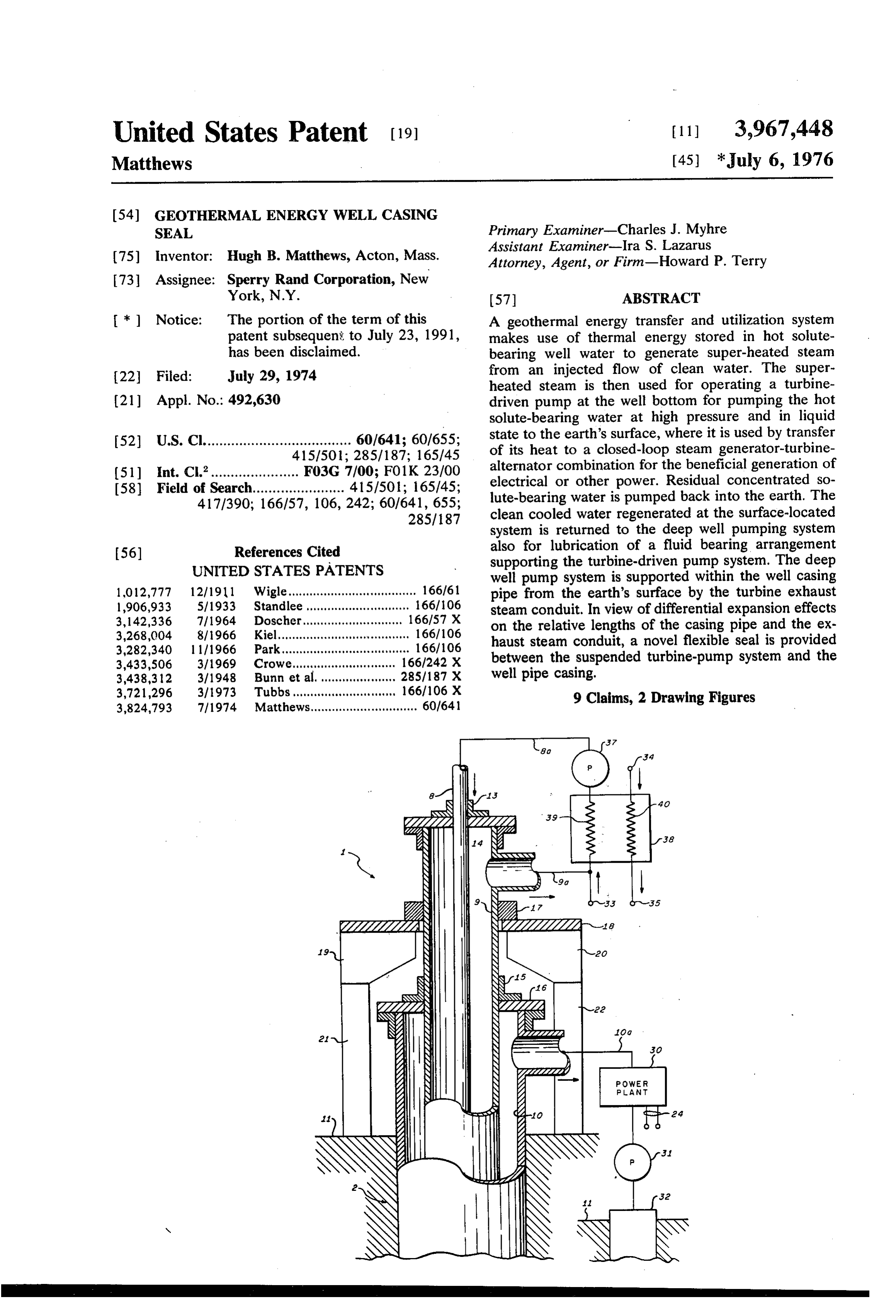
Page 1 — bibliographic record
United States Patent (19) 11 3,967,448 Matthews (45) *July 6, 1976
54). GEOTHERMAL ENERGY WELL CASING
SEAL Primary Examiner-Charles J. Myhre Assistant Examiner-Ira S. Lazarus 75) Inventor: Hugh B. Matthews, Acton, Mass. Attorney, Agent, or Firm-Howard P. Terry 73 Assignee: Sperry Rand Corporation, New
York, N.Y. 57 ABSTRACT * ) Notice: The portion of the term of this A geothermal energy transfer and utilization system patent subsequent to July 23, 1991, has been disclaimed.
makes use of thermal energy stored in hot solute bearing well water to generate super-heated steam 22 Filed: July 29, 1974 from an injected flow of clean water. The super heated steam is then used for operating a turbine (21) Appl. No.: 492,630 driven pump at the well bottom for pumping the hot solute-bearing water at high pressure and in liquid 52) U.S. Cl..................................... 60/641; 60/655;
state to the earth's surface, where it is used by transfer of its heat to a closed-loop steam generator-turbine (51) int. Cl.’...................... F03G 7/00; FO1K 23/00 alternator combination for the beneficial generation of 58) Field of Search....................... 4151501; 165,45; electrical or other power. Residual concentrated so 417/390; 166/57, 106, 242, 60/641, 655; lute-bearing water is pumped back into the earth. The 285/187 clean cooled water regenerated at the surface-located system is returned to the deep well pumping system 56) References Cited also for lubrication of a fluid bearing arrangement UNITED STATES PATENTS supporting the turbine-driven pump system. The deep well pump system is supported within the well casing l,012,777 12/19ll Wigle.................................... 166/61 pipe from the earth's surface by the turbine exhaust g: 3.18: St. A 6 s h so a w w a & w 3% steam conduit. In view of differential expansion effects
3,282,340 1 1/1966 Park.................................... 166/106 on the relative lengths of the casing pipe and the ex:
haust steam conduit, a novel flexible seal is provided 3,433,506 3/1969 Crowe.... 166/242 X between the suspended turbine-pump system and the 3,438,312 3/1948 Bunn et al. ... 285/187 x well pipe casing.
3,721296 3/1973 Tubbs........... ..., 166/106 X 3,824,793 7/1974 Matthews.............................. 60/64 9 Claims, 2 Drawing Figures
NSN
too
PANT
Page 2
Drawing sheet — no readable text.
Page 3
Drawing sheet — no readable text.
Page 4
GEOTHERMAL ENERGY WELL CASING SEAL BRIEF DESCRIPTION OF THE DRAWINGS
BACKGROUND OF THE INVENTION
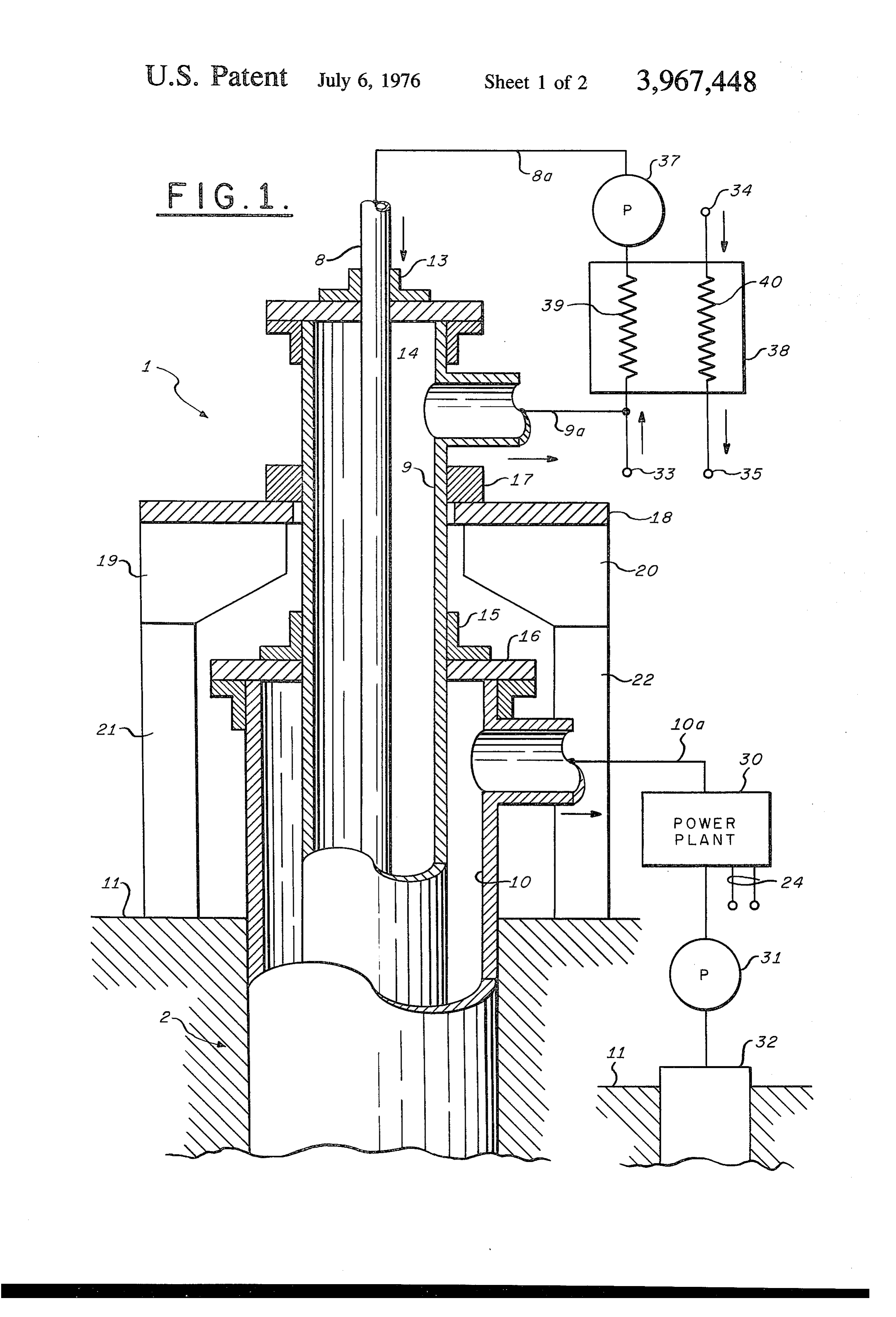
FIG. 1 is an elevation view, mostly in cross section, of the novel suspension arrangement of the deep well 1. Field of the Invention geothermal pumping apparatus.
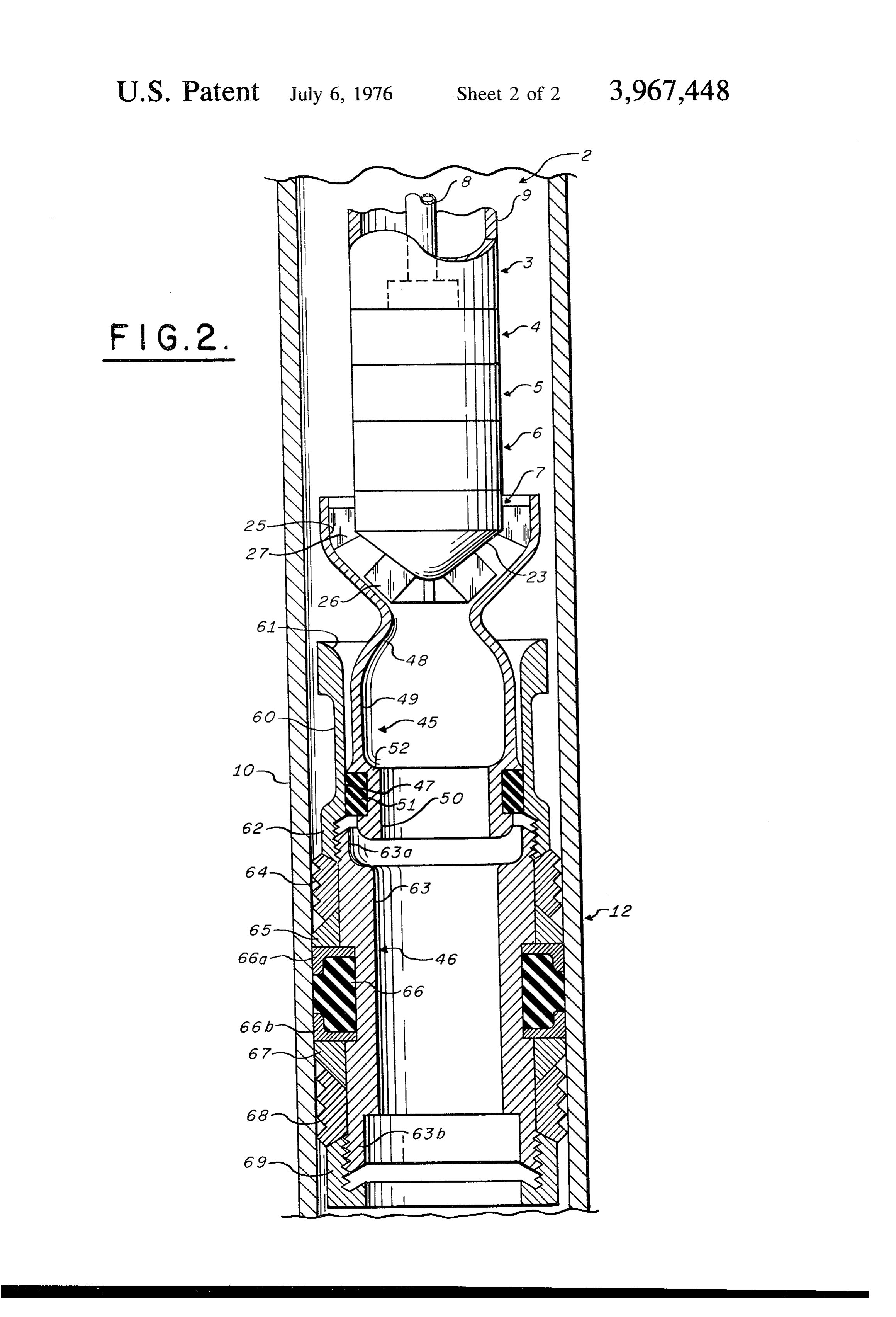
The invention relates generally to efficient means for FIG. 2 is an elevation view, mostly in cross section, of the generation of electrical or other power utilizing the deep well geothermal pump apparatus and of the energy from geothermal sources and, more particu novel sealing arrangement.
larly, relates to arrangements for suspending efficient DESCRIPTION OF THE PREFERRED super-heated steam generation and hot water pumping O EMBODIMENTS equipment in deep, hot water wells for the transfer of thermal energy to the earth's surface. FIGS. 1 and 2 illustrate the general structure and 2. Description of the Prior Art characteristics of that portion of the geothermal energy A prior art advance in the art of extraction and use of extraction system which is immersed in a deep well geothermal energy is reflected in the H. B. Matthews 5 extending into strata far below the surface of the earth,
thermal Energy System and Method’, filed Oct. 24, such that a copious supply of extremely hot water 1972, issued July 23, 1974 as U.S. Pat. No. 3,824,793, under high pressure is naturally available, the active and assigned to the Sperry Rand Corporation. This 20 pumping structure being located adjacent the hot water prior Matthews invention provides means for efficient source and within a generally conventional well casing power generation employing energy derived from geo pipe 10. The configuration in FIG. 1 is seen to include thermal sources through the generation of dry, super a well head section 1 located above the earth's surface heated steam and the consequent operation of sub-sur 11 and a main well section 2 extending downward from face equipment for pumping extremely hot well water 25 well head section 1 and below the earth's surface 11. At at high pressures upward to the earth's surface. Clean the subterranean source of hot, high pressure water, as shown in FIG. 2, the main well section 2 joins a steam water is injected at a first or surface station into the generator input section 3. The steam generator section deep well where thermal energy stored in hot solute 4, the steam turbine section 5, a rotary bearing section bearing deep well water is used at a second or deep well station to generate super-heated steam from the clean 30 6, and a hot water pumping section 7 follow in close water. The resultant dry super-heated steam is used at cooperative succession at increasing depths. At the the well bottom for operating a turbine-driven pump 7 is sealed to section lowest or seal 12, the input to the pump section pumping the hot solute-bearing well water to the first will be further described.wall of well casing pipe 10, as the inner station at the earth's surface, the water being pumped Referring again to FIG. 1, the well casing pipe 10 at all times and locations in the system at pressures 35 extends which prevent flash steam formation. The highly ener preferablydownward from the well head section 1 in concentric relation about an innermost getic water is used at the surface or first station in a stainless steel or other high binary fluid system so that its thermal energy is trans duit 8 for supplying a flow ofquality alloy pipe or con relatively cool and rela ferred to a closed-loop surface-located vapor genera tively pure water at the bottom of the well. A second tor-turbine system for driving an electrical power alter 40 relatively large pipe or conduit 9 of similar quality nator. Cooled, clean water is regenerated by the sur surrounding pipe 8 is also provided within well casing face system for re-injection into the well for operation10, extending from well head 1 to the energy conver of the steam turbine therein. Undesired solutes are sion and hot water pumping system at the bottom of the pumped back into the earth via a separate well in the well and permitting turbine exhaust steam to flow to form of a concentrated brine. 45 the surface of the earth.
SUMMARY OF THE INVENTION The clean water injection pipe 8 passes through a fitting 13 mounted on the apertured capping plate 14.
The invention is an improvement facilitating ready In similar manner the exhaust steam return pipe 9 installation and reliable operation of geothermal sys passes through a fitting 15 mounted on the apertured tems of the kind described in the prior Matthews pa 50 capping plate 16. While these generally concentric tent; according to the invention, there are provided structures may be integrated to a degree, it is intended novel means for the support of the deep well geother that the exhaust steam pipe 9 furnish the main support mal pump system within the well casing pipe from the for the deep well apparatus. For this purpose, a ring earth's surface by the pump-driving turbine exhaust collar 17 is welded or otherwise affixed about the ex steam conduit. In view of the differential expansion 55 haust steam pipe 9 immediately below its tee branch effects on the relative lengths of the casing pipe extend 9a. Ring collar 17 normally rests on a suitable horizon ing downward from the earth's surface and the exhaust tal platform 18 which may, in turn, be supported by steam conduit contained therein, a novel flexible seal is braces such as braces 19, 20 from associated vertical provided between the suspended geothermal pump support beams such as beams 21, 22. The latter are system and the well pipe casing. A first element of the 60 fixed in the earth, for example, by suitable concrete improvement provides a vertical smooth cylindrical foundation elements (not shown) that may take en sealing surface at the desired location for the deep well tirely conventional form. In this manner, the weight of apparatus by means itself fully sealed to the well casing the conduits within the well casing pipe 10 and the pipe. A second element assures easy assembly of a weight of the deep well geothermal pump apparatus second seal interfacing the cylindrical sealing surface 65 itself are primarily suspended from the exhaust steam and suspended from the hot water pump so as to permit return pipe 9 by platform 18.
sliding motion of the seal in the hostile prevailing envi It will be seen from FIGS. 1 and 2 that relatively ronment, yet affording reliable sealing action. clean and cool water is pumped by pump 37 through
Page 5
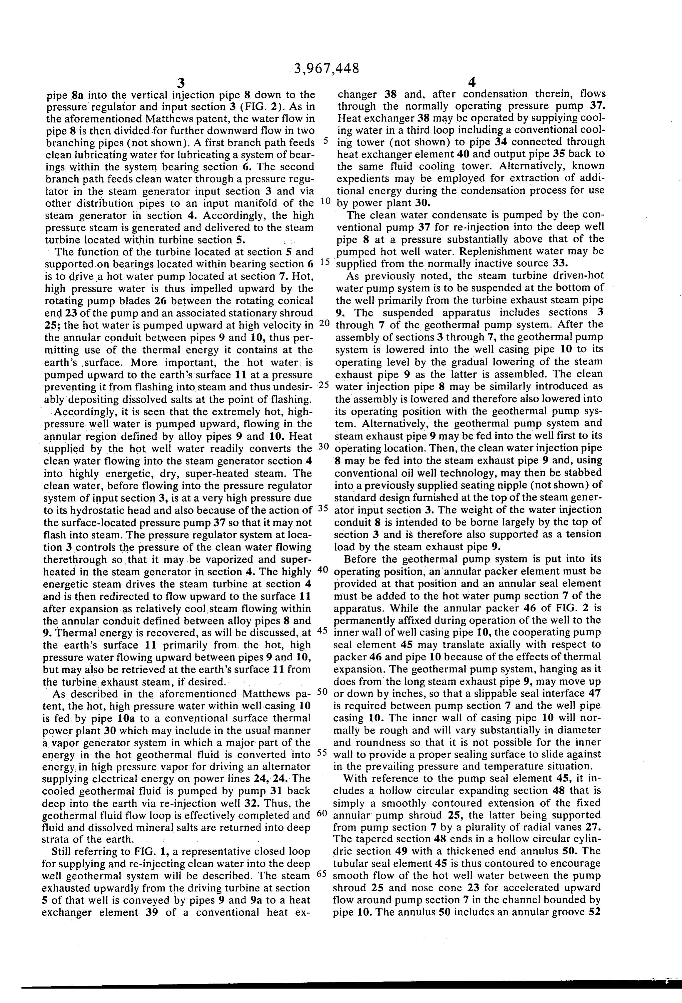
changer 38 and, after condensation therein, flows pipe 8a into the vertical injection pipe 8 down to the through pressure regulator and input section 3 (FIG. 2). As in the normally operating pressure pump 37. the aforementioned Matthews patent, the water flow in Heat exchanger 38 may be operated by supplying cool pipe 8 is then divided for further downward flow in two ing water in a third loop including a conventional cool branching pipes (not shown). A first branch path feeds ing tower (not shown) to pipe 34 connected through clean lubricating water for lubricating a system of bear heat exchanger element 40 and output pipe 35 back to ings within the system bearing section 6. The second the same fluid cooling tower. Alternatively, known branch path feeds clean water through a pressure regu expedients may be employed for extraction of addi lator in the steam generator input section 3 and via 10 tional energy during the condensation process for use other distribution pipes to an input manifold of the by power plant 30.
steam generator in section 4. Accordingly, the high The clean water condensate is pumped by the con pressure steam is generated and delivered to the steam ventional pump 37 for re-injection into the deep well turbine located within turbine section 5. pipe 8 at a pressure substantially above that of the The function of the turbine located at section 5 and pumped hot well water. Replenishment water may be supported on bearings located within bearing section 6 15 supplied from the normally inactive source 33. is to drive a hot water pump located at section 7. Hot, As previously noted, the steam turbine driven-hot high pressure water is thus impelled upward by the water pump system is to be suspended at the bottom of rotating pump blades 26 between the rotating conical the well primarily from the turbine exhaust steam pipe end 23 of the pump and an associated stationary shroud 20 9. The suspended apparatus includes sections 3 25; the hot water is pumped upward at high velocity in through 7 of the geothermal pump system. After the the annular conduit between pipes 9 and 10, thus per assembly of sections 3 through 7, the geothermal pump mitting use of the thermal energy it contains at the system is lowered into the well casing pipe 10 to its earth's surface. More important, the hot water, is operating level by the gradual lowering of the steam pumped upward to the earth's surface 11 at a pressure exhaust pipe 9 as the latter is assembled. The clean preventing it from flashing into steam and thus undesir 25 water injection pipe 8 may be similarly introduced as ably depositing dissolved salts at the point of flashing. the assembly is lowered and therefore also lowered into Accordingly, it is seen that the extremely hot, high its operating position with the geothermal pump sys pressure. well water is pumped upward, flowing in the tem. Alternatively, the geothermal pump system and annular region defined by alloy pipes 9 and 10. Heat steam exhaust pipe 9 may be fed into the well first to its supplied by the hot well water readily converts the 30 operating location. Then, the clean water injection pipe clean water flowing into the steam generator section 4 8 may be fed into the steam exhaust pipe 9 and, using into highly energetic, dry, super-heated steam. The conventional oil well technology, may then be stabbed clean water, before flowing into the pressure regulator into a previously supplied seating nipple (not shown) of system of input section 3, is at a very high pressure due standard design furnished at the top of the steam gener to its hydrostatic head and also because of the action of 35 ator input section 3. The weight of the water injection the surface-located pressure pump 37 so that it may not conduit 8 is intended to be borne largely by the top of flash into steam. The pressure regulator system at loca section 3 and is therefore also supported as a tension tion 3 controls the pressure of the clean water flowing load by the steam exhaust pipe 9. therethrough so... that it may be vaporized and super Before the geothermal pump system is put into its heated in the steam generator in section 4. The highly 40 operating position, an annular packer element must be energetic steam drives the steam turbine at section 4 provided at that position and an annular seal element and is then redirected to flow upward to the surface 11 must be added to the hot water pump section 7 of the after expansion as relatively cool steam flowing within apparatus. While the annular packer 46 of FIG. 2 is the annular conduit defined between alloy pipes 8 and 45 permanently affixed during operation of the well to the 9. Thermal energy is recovered, as will be discussed, at inner wall of well casing pipe 10, the cooperating pump the earth's surface 11 primarily from the hot, high seal element 45 may translate axially with respect to pressure water flowing upward between pipes 9 and 10, packer 46 and pipe 10 because of the effects of thermal but may also be retrieved at the earth's surface 11 from expansion. The geothermal pump system, hanging as it the turbine exhaust steam, if desired. does from the long steam exhaust pipe 9, may move up As described in the aforementioned Matthews pa 50 or down by inches, so that a slippable seal interface 47 tent, the hot, high pressure water within well casing 10 is required between pump section 7 and the well pipe is fed by pipe 10a to a conventional surface thermal casing 10. The inner wall of casing pipe 10 will nor power plant 30 which may include in the usual manner mally be rough and will vary substantially in diameter a vapor generator system in which a major part of the and roundness so that it is not possible for the inner energy in the hot geothermal fluid is converted into 55 wall to provide a proper sealing surface to slide against energy in high pressure vapor for driving an alternator in the prevailing pressure and temperature situation. supplying electrical energy on power lines 24, 24. The With reference to the pump seal element 45, it in cooled geothermal fluid is pumped by pump 31 back cludes a hollow circular expanding section 48 that is deep into the earth via re-injection well 32. Thus, the simply a smoothly contoured extension of the fixed geothermal fluid flow loop is effectively completed and 60 annular pump shroud 25, the latter being supported fluid and dissolved mineral salts are returned into deep from pump section 7 by a plurality of radial vanes 27. strata of the earth. The tapered section 48 ends in a hollow circular cylin Still referring to FIG. 1, a representative closed loop dric section 49 with a thickened end annulus 50. The for supplying and re-injecting clean water into the deep 65 tubular seal element 45 is thus contoured to encourage well geothermal system will be described. The steam smooth flow of the hot well water between the pump exhausted upwardly from the driving turbine at section shroud 25 and nose cone 23 for accelerated upward 5 of that well is conveyed by pipes 9 and 9a to a heat flow around pump section 7 in the channel bounded by exchanger element 39 of a conventional heat ex pipe 10. The annulus 50 includes an annular groove 52
Page 6
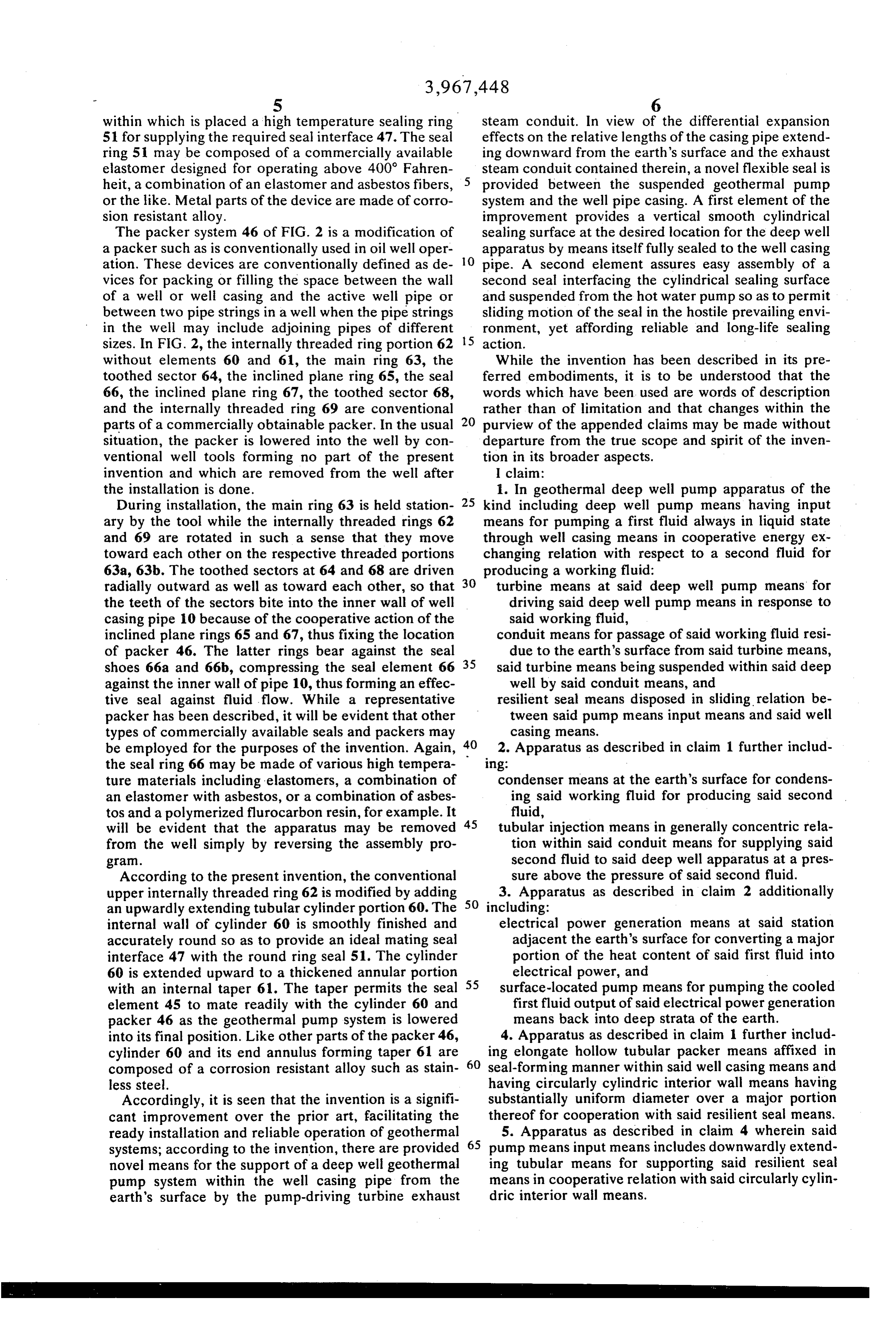
S 6 within which is placed a high temperature sealing ring steam conduit. In view of the differential expansion 51 for supplying the required seal interface 47. The seal effects on the relative lengths of the casing pipe extend ring 5 may be composed of a commercially available ing downward from the earth's surface and the exhaust elastomer designed for operating above 400 Fahren steam conduit contained therein, a novel flexible seal is heit, a combination of an elastomer and asbestos fibers, provided between the suspended geothermal pump or the like. Metal parts of the device are made of corro system and the well pipe casing. A first element of the sion resistant alloy. improvement provides a vertical smooth cylindrical The packer system 46 of FIG. 2 is a modification of sealing surface at the desired location for the deep well a packer such as is conventionally used in oil well oper apparatus by means itself fully sealed to the well casing ation. These devices are conventionally defined as de O pipe. A second element assures easy assembly of a vices for packing or filling the space between the wall second seal interfacing the cylindrical sealing surface of a well or well casing and the active well pipe or and suspended from the hot water pump so as to permit between two pipe strings in a well when the pipe strings sliding motion of the seal in the hostile prevailing envi in the well may include adjoining pipes of different ronment, yet affording reliable and long-life sealing sizes. In FIG. 2, the internally threaded ring portion 62 5 action.
without elements 60 and 61, the main ring 63, the While the invention has been described in its pre toothed sector 64, the inclined plane ring 65, the seal ferred embodiments, it is to be understood that the 66, the inclined plane ring 67, the toothed sector 68, words which have been used are words of description and the internally threaded ring 69 are conventional rather than of limitation and that changes within the parts of a commercially obtainable packer. In the usual 20 purview of the appended claims may be made without situation, the packer is lowered into the well by con departure from the true scope and spirit of the inven ventional well tools forming no part of the present tion in its broader aspects.
invention and which are removed from the well after I claim:
the installation is done. 1. In geothermal deep well pump apparatus of the During installation, the main ring 63 is held station 25 kind including deep well pump means having input ary by the tool while the internally threaded rings 62 means for pumping a first fluid always in liquid state and 69 are rotated in such a sense that they move through well casing means in cooperative energy ex toward each other on the respective threaded portions changing relation with respect to a second fluid for 63a, 63b. The toothed sectors at 64 and 68 are driven producing a working fluid.
radially outward as well as toward each other, so that 30 turbine means at said deep well pump means for the teeth of the sectors bite into the inner wall of well driving said deep well pump means in response to casing pipe 10 because of the cooperative action of the said working fluid, inclined plane rings 65 and 67, thus fixing the location conduit means for passage of said working fluid resi of packer 46. The latter rings bear against the seal due to the earth's surface from said turbine means, shoes 66a and 66b, compressing the seal element 66 35 said turbine means being suspended within said deep against the inner wall of pipe 10, thus forming an effec well by said conduit means, and tive seal against fluid flow. While a representative resilient seal means disposed in sliding relation be packer has been described, it will be evident that other tween said pump means input means and said well types of commercially available seals and packers may casing means.
be employed for the purposes of the invention. Again, 40 2. Apparatus as described in claim 1 further includ the seal ring 66 may be made of various high tempera Ing:
ture materials including elastomers, a combination of condenser means at the earth's surface for condens an elastomer with asbestos, or a combination of asbes ing said working fluid for producing said second tos and a polymerized flurocarbon resin, for example. It 45 fluid, will be evident that the apparatus may be removed tubular injection means in generally concentric rela from the well simply by reversing the assembly pro tion within said conduit means for supplying said gram. second fluid to said deep well apparatus at a pres According to the present invention, the conventional sure above the pressure of said second fluid. upper internally threaded ring 62 is modified by adding 50 3. Apparatus as described in claim 2 additionally an upwardly extending tubular cylinder portion 60. The including:
internal wall of cylinder 60 is smoothly finished and electrical power generation means at said station accurately round so as to provide an ideal mating seal adjacent the earth's surface for converting a major interface 47 with the round ring seal 51. The cylinder portion of the heat content of said first fluid into 60 is extended upward to a thickened annular portion 55 electrical power, and with an internal taper 61. The taper permits the seal surface-located pump means for pumping the cooled element 45 to mate readily with the cylinder 60 and first fluid output of said electrical power generation packer 46 as the geothermal pump system is lowered means back into deep strata of the earth. into its final position. Like other parts of the packer 46, 4. Apparatus as described in claim 1 further includ cylinder 60 and its end annulus forming taper 61 are ing elongate hollow tubular packer means affixed in composed of a corrosion resistant alloy such as stain 60 seal-forming manner within said well casing means and less steel. having circularly cylindric interior wall means having Accordingly, it is seen that the invention is a signifi substantially uniform diameter over a major portion cant improvement over the prior art, facilitating the thereof for cooperation with said resilient seal means. ready installation and reliable operation of geothermal 5. Apparatus as described in claim 4 wherein said systems; according to the invention, there are provided 65 pump means input means includes downwardly extend novel means for the support of a deep well geothermal ing tubular means for supporting said resilient seal pump system within the well casing pipe from the means in cooperative relation with said circularly cylin earth's surface by the pump-driving turbine exhaust dric interior wall means.
Page 7
6. Apparatus as described in claim 5 wherein said said outwardly and inwardly directed flared surface circularly cylindric interior wall means has a diameter forming means thereby aiding the telescoping of less than the diameter of the outer wall of said down said circularly cylindric wall means and said down wardly extending tubular means so as to cooperate in wardly extending tubular means during installation spaced telescoping relation. of said geothermal deep well apparatus. 7. Apparatus as described in claim 6 wherein: 8. Apparatus as described in claim 7 wherein said said circularly cylindric interior wall means has a resilient seal means comprises annular elastic ring portion opposite said elongate hollow tubular means supported in a groove adjacent said inwardly packer means having outwardly directed annular 10 directed annular flared surface means.
flared surface means. 9. Apparatus as described in claim 8 wherein said said downwardly extending tubular means has a por annular elastic ring is composed at least in part of a tion opposite said pump means having inwardly high temperature elastomer.
directed annular flared surface means, and
Provenance
- Collection
- Cited prior art
- Original PDF
- patentimages.storage.googleapis.com →
- Filed
- 1974-07-29
- Pages
- 7
- Method
- pdftotext (the PDF's own text layer) + pdftoppm 300dpi page scans
- Source
- Google Patents bibliographic record
- Granted
- 1976-07-06
- Inventors
- Hugh B. Matthews; Sperry Rand Corp
- Transcribed from
- patentimages.storage.googleapis.com →