patent · US3991817
Geothermal energy recovery
16 November 1976
Page 1 — bibliographic record
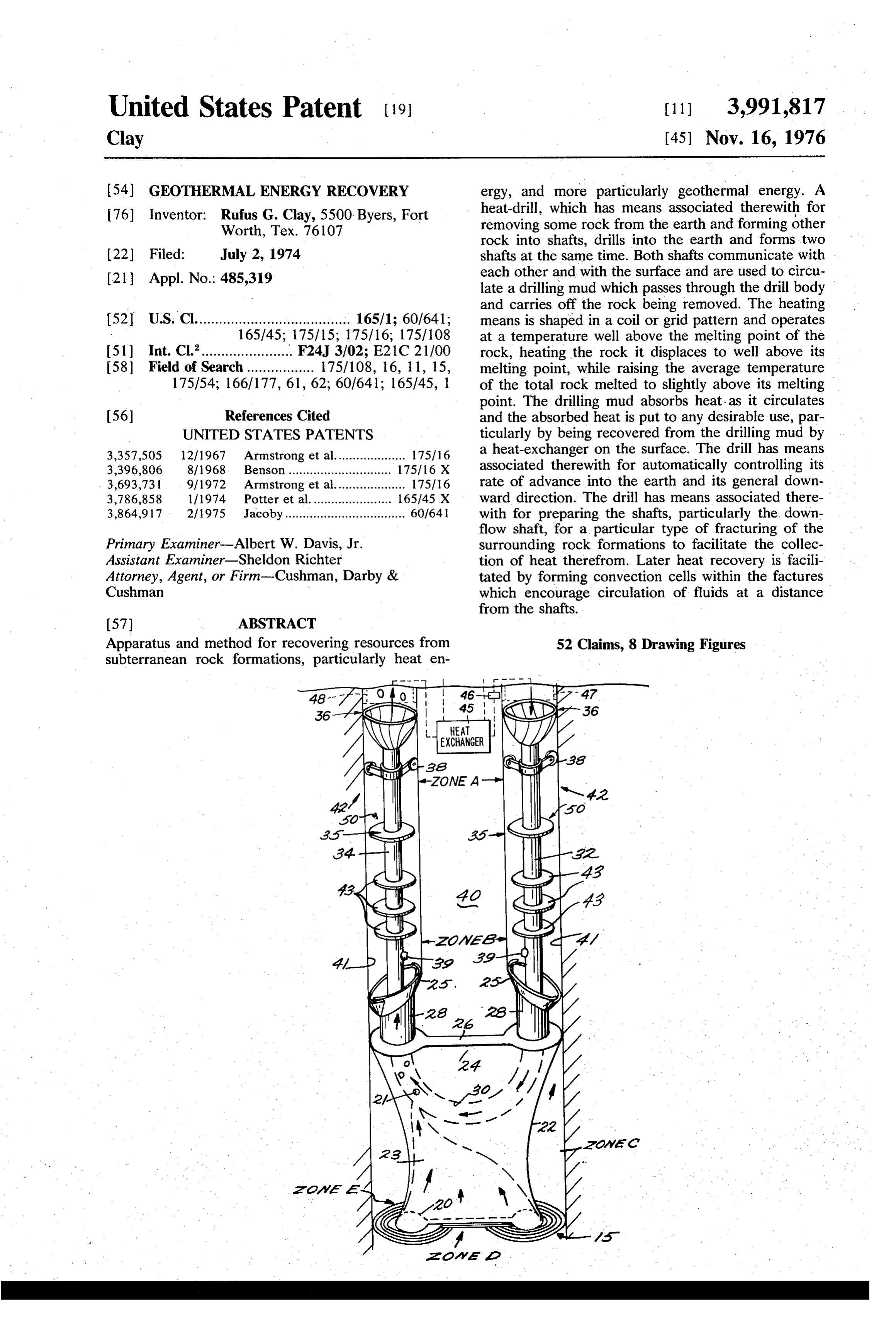
United States Patent (19) 11, 3,991,817 Clay (45) Nov. 16, 1976 54 GEOTHERMAL ENERGY RECOVERY ergy, and more particularly geothermal energy. A 76 Inventor: Rufus G. Clay, 5500 Byers, Fort heat-drill, which has means associated therewith for Worth, Tex. 76107 removing some rock from the earth and forming other rock into shafts, drills into the earth and forms two 22 Filed: July 2, 1974 shafts at the same time. Both shafts communicate with 21 Appl. No.: 485,319 each other and with the surface and are used to circu late a drilling mud which passes through the drill body and carries off the rock being removed. The heating 52 U.S. Cl....................................... 165/1; 60/641; means is shaped in a coil or grid pattern and operates 165/45; 175/15; 175/16; 175/108 at a temperature well above the melting point of the 51) Int. Cl.'....................... F24J 3/02; E21C 21100 rock, heating the rock it displaces to well above its 58 Field of Search ................. 175/108, 16, 11, 15, melting point, while raising the average temperature 175/54; 166/177, 61, 62; 60/641; 165/45, 1 of the total rock melted to slightly above its melting point. The drilling mud absorbs heat, as it circulates 56) References Cited and the absorbed heat is put to any desirable use, par UNITED STATES PATENTS ticularly by being recovered from the drilling mud by 3,357,505 12/1967 Armstrong et al.................... 1751.16 a heat-exchanger on the surface. The drill has means 3,396,806 8, 1968. Benson ............................. 17516 X associated therewith for automatically controlling its 3,693,731 9/1972 Armstrong et al.................... 1751.16 rate of advance into the earth and its general down 3,786,858 111974 Potter et al....................... 165145 X ward direction. The drill has means associated there 3,864,917 2/1975 Jacoby.................................. 60/64 with for preparing the shafts, particularly the down flow shaft, for a particular type of fracturing of the
Primary Examiner-Albert W. Davis, Jr. surrounding rock formations to facilitate the collec Assistant Examiner-Sheldon Richter tion of heat therefrom. Later heat recovery is facili Attorney, Agent, or Firm-Cushman, Darby & tated by forming convection cells within the factures Cushman which encourage circulation of fluids at a distance from the shafts.
Apparatus and method for recovering resources from 52 Claims, 8 Drawing Figures subterranean rock formations, particularly heat en
Page 2
Drawing sheet — no readable text.
Page 3
Drawing sheet — no readable text.
Page 4
Drawing sheet — no readable text.
Page 5
Drawing sheet — no readable text.
Page 6
Drawing sheet — no readable text.
Page 7
part of the hole it can reach in a hole of decreasing
GEOTHERMAL ENERGY RECOVERY diameter, requiring each casing to fit inside the ones
BACKGROUND AND SUMMARY OF THE
already in place and hence be of successively smaller
INVENTION
diameter, requiring repeated recovery and replacement of the worn drills; requiring each drill used to be able to
The invention relates to a method and apparatus for fit in the smallest part of the shaft at the bottom and recovering resources from below the earth's surface, hence be smaller than the last; requiring each succes particularly heat, and particularly geothermal energy sive drill to fit in the casings in place and hence be resources. It is generally recognized by geologists that smaller for each new casing; not usefully recovering within a distance of 20 miles beneath any point of the 10 any of the energy expended in the drilling operation; earth's surface, including the ocean floors, tempera not usefully recovering the energy resources drilled for tures reach levels that would usefully power heat en until after the completion of the drilling process; need gines. The only previous barrier to the recovery of such ing separate operations in addition to drilling to be energy resources was the difficulty of providing ade 15 performed to perforate the casings before circulation quate heat-exchanging means at depths with substantial of fluids between the shaft and the surrounding forma geothermal resources. Once that barrier is overcome at tions begins; requiring separate operations in addition a certain point of the earth's surface that point be to drilling to be performed to the casings to prepare for comes a suitable site for geothermal energy recovery fracturing operations on the surrounding rock; having operations. Geologists believe that the easily available no suitable means in heat-drilling operations of control geothermal resources which have been successfully 20 ling the position or orientation of fractures which may recovered in the past existed close to the earth's sur be desirable and avoiding fractures which may be unde face as the result of natural heat-exchanging mecha sirable; having no suitable means of connecting two nisms at greater depths. These natural heat-exchanging separate holes in solid rock other than fracturing the formations make available only a minute fraction of the 25 rock to form connecting passages from hole to hole; potential resources lying within 20 miles of the surface. having no suitable means to extend a producing two The earth's total geothermal resources greatly exceed hole geothermal well to a greater depth without sealing the world's energy needs, not only for today but for the the connecting passages between the holes; requiring foreseeable future. These resources have been almost heat-drills to apply their thrusting force to their heating totally inaccessible to past methods and apparatus, not 30 surfaces to move molten rock and the drill; requiring because the drilling apparatus had not reached a high heat-drills to apply such force to their heating surfaces state of development, but because of the inherent limi that employable temperatures are limited by the struc tations, both technological and economic, of the past tural strength of the materials rather than by the mate drilling methods. The present invention overcomes all rials' stability at higher temperatures. The method and of the limitations inherent in the prior methods. It is the 35 apparatus of the present invention overcomes all of the purpose of the present invention to make the geother above mentioned drawbacks.
mal resources of the earth generally accessible to meet According to the teachings of the present invention, the world's great need for energy, particularly for non a drill body having a particular shape with a heating polluting energy, which is an essential requirement of element of a particular configuration attached thereto life and prosperity. is used to drill into the earth and from two shafts at the In the past it has been proposed to drill two separate 40 same time in the earth. The two shafts are in fluid com holes into a solid rock formation with heat-drills or munication through the body of the drill and are used other drills, fracture the rock hydraulically or by nu to circulate a "drilling mud' through the drill body to clear explosions to create connecting passages for fluid carry off excess rock. The heating element operates at flow, and then circulate fluid down one hole, through 45 a temperature well above the melting point of the rock, the connecting passages and up the other hole to re melts through rock ahead of the drill body, and raises cover heat. In the case of nuclear explosions part of the the rock through which it passes to well above the heat generated by the nuclear reaction would also be rock's melting point, raising the average temperature of recoverable. It has also been proposed to drill one hole, the rock through which the drill body passes, however, remove the drill, and insert pipes into the hole through to a selected lower degree above the rock's melting which a fluid would circulate to remove heat (see U.S. 50 point. The heating element passes through a plurality of Pat. Nos. 3,274,769; 3,470,943; and 3,521,699). Vari rock portions spaced throughout the region to be ous types of apparatus have been proposed for doing melted, and sweeps through only a fraction of the spa the drilling, such as the heat-drills disclosed in U.S. Pat. tial volume swept out by the drill body. The molten Nos. 3,396,806; 3,357,505, and 3,693,731. While prior rock takes one of two alternate paths: it either flows methods and apparatus are in general satisfactory, they 55 into the interior of the drill body and thence into the generally have one or more of the following drawbacks: drilling mud circulating through the drill body and requiring separate drilling operations for each hole; thence to the surface; or it flows around the exterior of requiring drilling pipe of a length on the order of the the drill body to the top of the drill body, which makes depth of the hole to circulate drilling mud to remove 60 two shafts in the molten rock. Means are provided for excess rock; requiring considerable mechanical force making the shafts the desired shape, for the gradual to be applied to the drill as an essential part of the cooling of the shaft walls, and for the maintenance of drilling operation; causing considerable abrasion of the the molten rock in the desired shape until the rock drill which tends to wear down the radial dimension of solidifies leaving two permanent shafts. Means are also the drill and reduce the cross-sectional dimensions of provided for causing the shafts formed to spiral around the hole; requiring repeated casings to be positioned 65 one another in a controlled manner. each extending from the surface to the vicinity of the The walls of the downflow shaft are formed with one hole botton at the time to prevent collapse of the shaft or more grooves extending throughout the length of the walls; requiring each casing to fit inside the smallest shaft, shaped like a V cut into the wall. The grooves are
Page 8
made to facilitate later fracturing of the surrounding solid rock according to the teachings of the present rock, and a concentration of thermal stress at the apex invention;
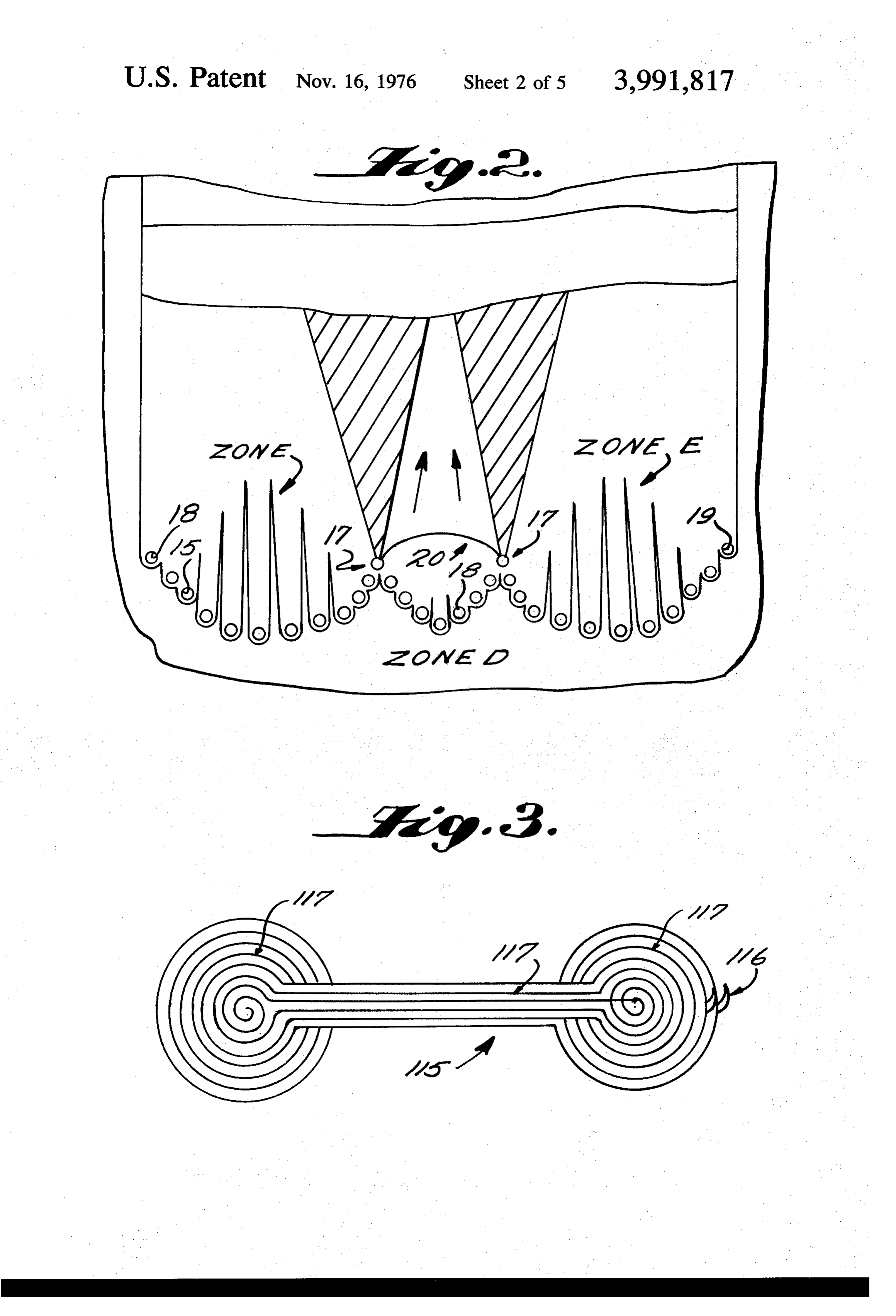
of the V cut also facilitates later fracturing and may FIG. 2 is a cross-sectional view taken along lines 2-2 even cause initial fractures to form at the apex by ther of FIG. 1 showing an exemplary heating coil according mal stress. The drilling mud circulating through the to the teachings of the present invention; drill body and the shafts absorbs heat in its passage and FIG. 3 is a perspective view of another heating ele that heat may be utilized while drilling is taking place; ment utilizable according to the teachings of the pre in particular a well-known effect due to absorbed heat sent invention;
is the “thermosyphonic effect' which creates a driving O FIG. 4 is a diagrammatic view showing fractures force acting on the fluid in its direction of motion and formed in the outside walls of the shaft according to the which may in some cases be the only pumping force teachings of the present invention;
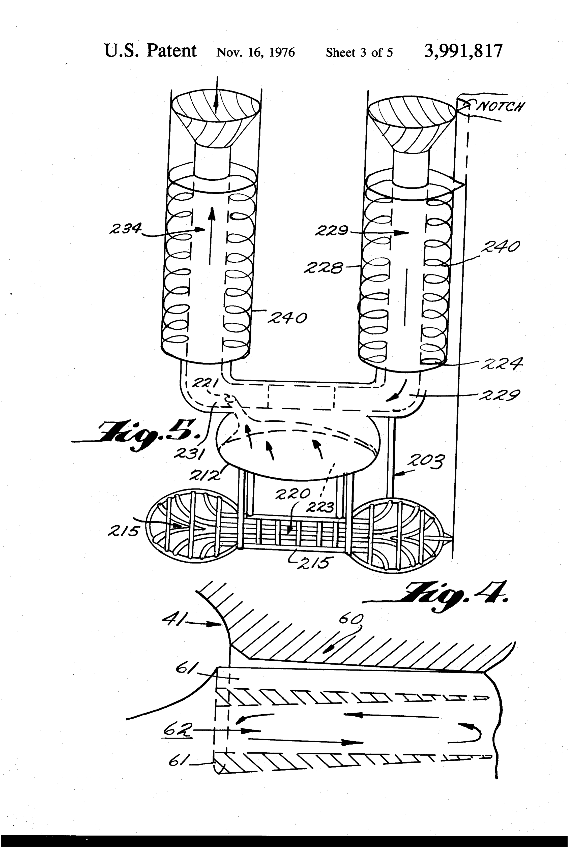
needed to circulate the fluid. A heat exchanger at the FIG. 5 is a perspective diagrammatic view of another surface removes heat from the drilling mud for any form of the apparatus according to the teachings of the desired use, particularly to help provide energy to the 5 present invention;
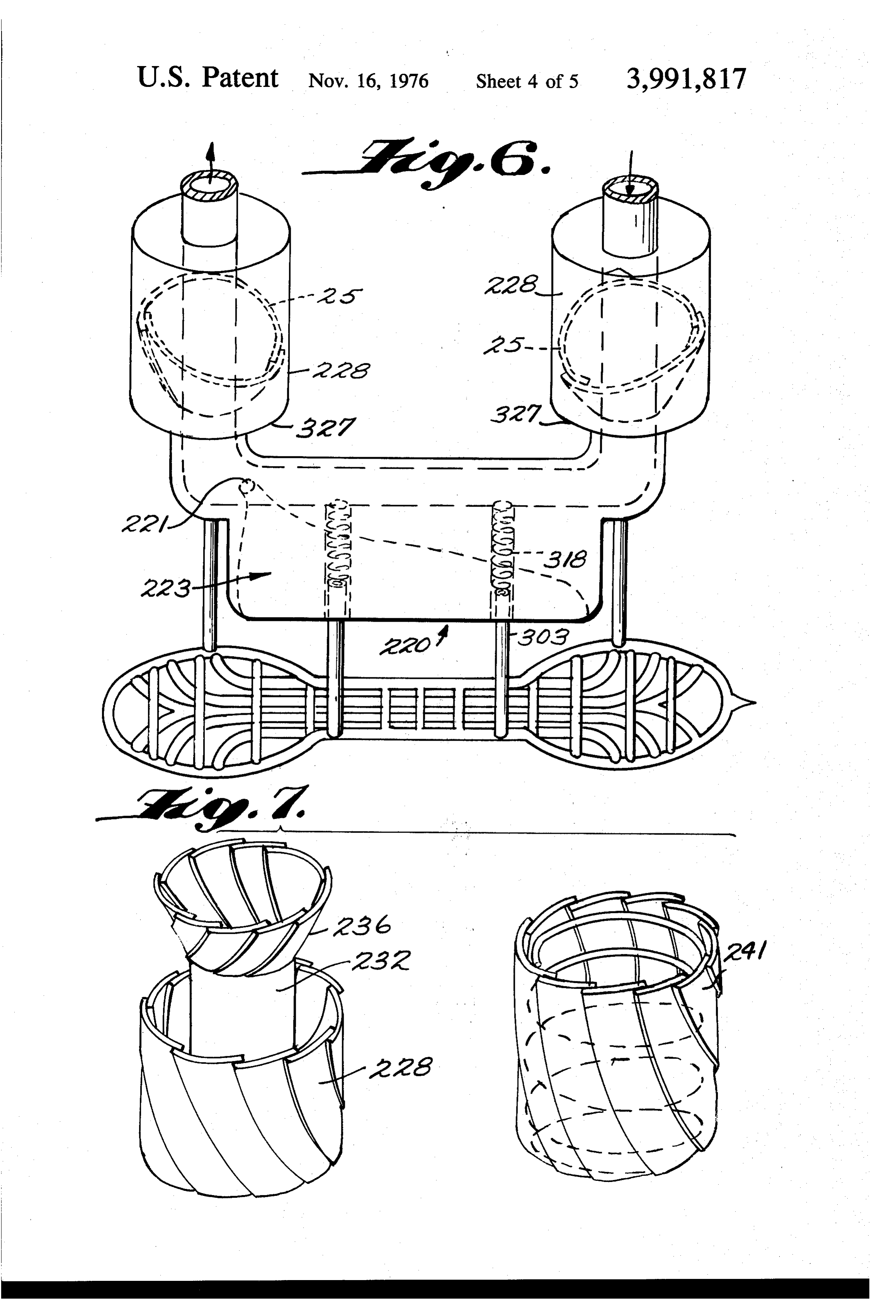
drilling operation. FIG. 6 is a partial view of a modified form of the Once the drill has reached the desired depth, frac apparatus shown in FIG. 5;
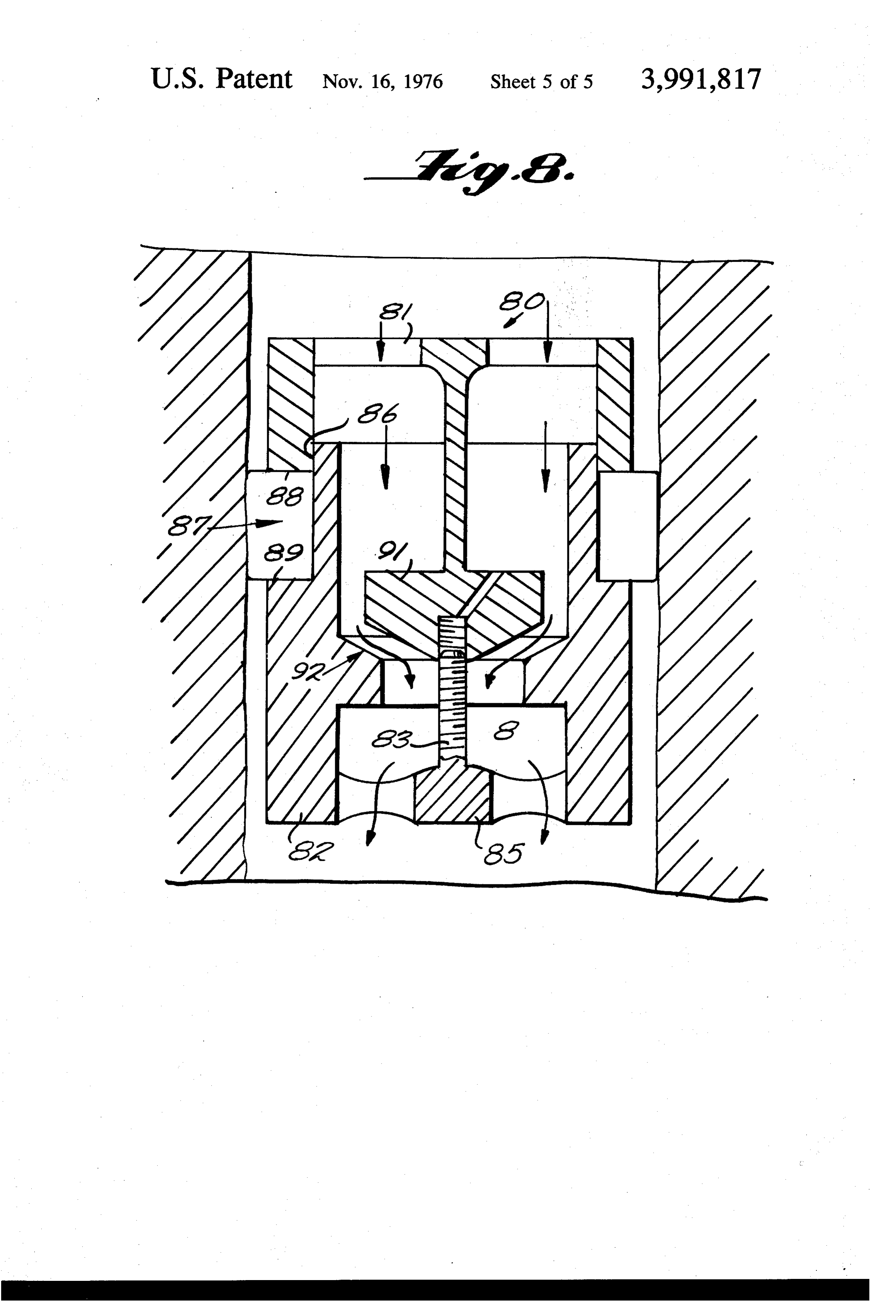
FIG. 7 is a detail view of another modification of the tures extending into the surrounding rock are intro duced through the grooves hydaulically, propped open apparatus of FIG. 5, and by well-known means, and partitioned by material exemplary FIG. 8 is a cross-sectional diagrammatic view of apparatus for applying hydraulic pressure to forced horizontally into the fractures at selected depths create or extend fractures.
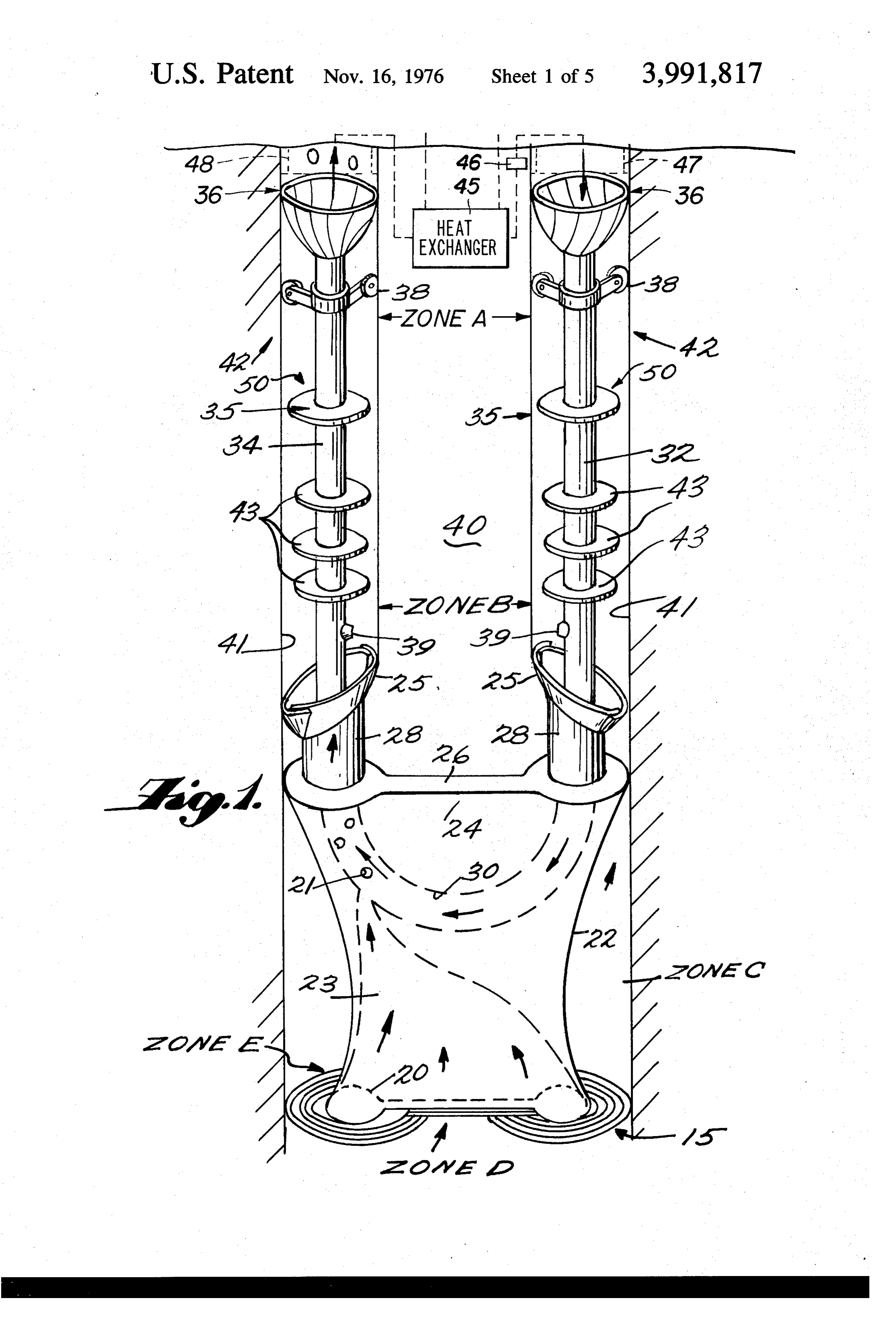
to form heat-collecting cells. If the shafts spiral around one another the fracture surfaces radiating from the DETALED DESCRIPTION OF THE INVENTION downflow shaft will spiral in the same direction and rate as the shafts, and will resemble helical surfaces. 25 Apparatus for drilling into rock formations and facili The drilling mud, or a fluid which replaces the drilling tating recovery of geothermal energy therefrom is shown generally at 10 in FIG. 1. The drilling means mud, will collect heat from the surrounding rock as the comprises a body portion 12 and a heating element 15. fluid circulates through the shafts, the fracture cells, The element 15 is preferably made of a refractory ma and the drill body. As the drilling progresses the “ther terial, for example mosyphonic effect' provides a pumping action to the 30 made of a numberpyrolytic of graphite or tungsten, and is straight or curved rod-like sec circulating fluid which will increase to the point that a tions, heated by passing an electric current there turbine may need to be placed in the flow stream to through, spaced in a grid or coil pattern such as 18, limit the rate of flow. The turbine may be placed in connected to the drill body at points 17 (see either the downflow shaft or the upflow stream, but the and able to spring somewhat back and forthFIG. in
the downflow does not contain the rock being removed and 35 direction of motion of the drill. This element may be may be preferred. The turbine may also be used to enclosed in a casing. The drill body is preferably made provide power. The drill may be re-started at a later of a refractory material, including electrical insulation date to proceed to a lower level without any need to such as boron nitride. A wider selection of materials seal off the fractures. Fractures extending from one may be used for the drill body inclding ceramics and shaft do not form part of connecting passages to the 40 even brick. The drill body has an orifice 20 on its un other shaft, so all fluid circulating from one shaft to the dersurface, shaped side surfaces 22, a lip portion 24, other passes through the drill body. flexible flanges 25, a top surface 26 and shaping por It is the principal object of this invention to recover tions 28. The shaping portions form shafts having a geothermal heat from the earth in a manner which may cross-sectional area approximately equal to the cross be more widely applied to a greater variety of geologi 45 sectional area of the orifice 20. The orifice communi cal formations than current methods. It is a further cates with a curved pipe section 30 within the drill body object of this invention to provide a method of drilling 12 via a channel 23 anad an aperture 21. which can drill to greater depths than drills in the past. The heating element 15 melts through the rock in It is a further object of this invention to provide mans to advance of the main drill body 12, and is operated at a study regions within the earth including those under 50 temperature well above the melting point of the sur ice, which have been known only by theory before, and rounding rock. One of the rocks which the present whose resources are thus largely a matter of specula invention particularly is intended to drill is granite. tion. It may for example be possible that the oil and gas Granite has a melting point of approximately 1200° C. resources currently found near the surface trapped in The heating element must be capable of being heated sedimentary rock formations are deposits of chemicals 55 to well above 1200 C without melting or deteriorating migrating through the basement rock from greater even after prolonged use. A preferred operating tem depths, and fluids circulating through fractures in the perature would have the heating element at about twice solid rock at sufficient depth may absorb useful the absolute temperature of the rock's melting point, or amounts of such petrochemicals; thus exploration of about 2700 C in the case of granite. The heating ele unknown regions for unknown resources is a further 60 ment 15, in the shape of a grid or coil, melts through object of this invention. These and other objects of the the rock in a grid or coil pattern, and passes through present invention will become clear upon an inspection only a fraction of the total volume of rock being of the detailed description of the invention and from melted: thus it displaces the rock, as it passes, only a the appended claims. distance on the order of the diameter of the rod-like 65 shape of the individual coils 18 of the heating element
BRIEF DESCRIPTION OF THE DRAWINGS
15, and in passing melts only slightly more than the
FIG. 1 is a perspective diagrammatic view of the volume of rock it displaces. The remaining solid rock preferred embodiment of the apparatus for drilling passes through the openings in the coils or grid and is
Page 9
S 6 melted by conduction from the hotter rock before the distance from the solid rock. The body of the drill does drill body 12 reaches it. This method and apparatus not tough solid rock, the rock it touches having been combine three important features which allow the heat melted before the drill body reaches it. The heating ing element to penetrate the rock with lower resistance 5 element operates at a nearly constant temperature, so than earlier approaches. First, molten rock must be the molten rock's average temperature is primarily displaced from the surface of the heating element to determined by the rate of advance of the drill and expose other rock to heat; as long as the molten rock hence the heating element through the rock. This aver lies between the heating element and the rock which age temperature determines the rock's viscosity, which needs to be melted, it acts as an insulator; in the present 10 undergoes its greatest change near the melting point of invention the rock needs only to be displaced on the the rock. The drill body advances at a rate determined order of the small diameter of the rod-like element, by the viscosity of the rock it penetrates. There is a rate rather than on the order of the diameter of the drill at which the forces balance one another: if the drill body as in earlier devices. Second, the rock being dis body speeds up the average temperature of the molten placed by the heating element is much hotter than the 5 rock it encounters will be less and hence the viscosity average rock melted, and hence has lower viscous resis will be greater and the drill will slow down; conversely tance. Third, viscous resistance acts on the heating if the drill slows down below the rate which balances element only the comparatively short time needed to the forces, the average temperature of the molten rock displace the rock. These features allow the heating it encounters will be higher and hence the viscosity will element to operate at higher temperatures than devices be lower and the drill will speed up. The weight of the in the past, and hence drill much more rapidly, since 20 drill may be altered by attaching weights (not shown) the heating element encounters comparatively little to it, and this will provide the means of controlling the resistance, and hence little stress. The total volume of balancing point as desired; the desired balancing point rock melted is, however, raised only to a desired point is one where the rock is hot enough to uniformly melt above its melting point. This represents an economic 25 but cool enough to be quickly solidified around the advantage, combining rapid penetration of the rock shafts.
with low overall melting temperatures. A coil or grid Although the body 12 of the drill does not touch solid shaped element 15 obviously would have the same rock, advantages in drilling a single shaft instead of a double shapingthemeans flexible flanges 25 which form part of the 28, are designed to push against molten shaft.
The heating element may be made in a springy form rock from portionsare 30 rock as the shafts made and scrape away molten of the underlying solid rock, and able to spring up and down without deforming perma may tough the solid rock. The portion of the heating nently, or it may be made rigid and able to ride up and element lying below the orifice 20 raises the rock to a down on rods which ride on springs (see FIG. 6). In the higher average temperature to facilitate the flow of the form which is springy there is a greater radial concen 35 rock through the channel 23 and aperture 21. tration of rods or loops 18 around the points of attach The channel 23 and aperture 21 may be insulated ment 17 (see FIG. 2), where the loops are not free to with a layer of pyrolytic graphite which keeps the rock ride up and down to absorb stress, and another concen tration of rods or loops 18 around the outer perimeter from ture, cooling on the surfaces of the channel or aper and in fact keeps the rock near the surface at the 19 to protect the outline cross-section. The dimensions hottest temperature within the channel. Pyrolytic of the molten pool of rock are important to the rate of 40 graphite has an anisotropic thermal conductivity that is advance of the drill, and the springlike form and the very high along its basal planes and very low perpendic concentration of rods or loops 18 around the outer ular to the basal planes giving an ideal combination of perimeter allow the pool to retain a substantially con conductivity and insulation to the channel stant cross-sectional shape. The cross-sectional area ture 21. The basal planes of the graphite lie23parallel and aper
decreases slightly as the element rides up, which slows 45 the walls of the channel and thus conduct heat well the rate of advance of the drill body, as will be ex plained later. This action protects the element from along the walls and poorly through the walls. The great damaging stresses caused by too rapid a rate of ad est concentration of heat is immediately below the vance. The above features are designed to minimize opening 20, and thus the heat conducted up the walls of accidental stresses on the heating element 15 so that 50 the channel is at a maximum, facilitating the flow of the heating element may be operated at high tempera rock through the channel.
tures where its structural strength may be small, but ofThe pipe 30 within the drill body 12 conducts a flow drilling mud therethrough. It connects the input pipe where it is otherwise stable. The present invention separates the functions of the heating element and the 55 32 and the output pipe 34. The pipe dimensions are drill body: the heating element's function is to heat, not important to the shape of the drill body, which must to apply substantial forces to move or shape the rock. insulate the pipe from the surrounding molten rock. The body of the drill 12 moves and shapes the rock, The pipe is preferably ovoid in cross-section, with the and provides the means of controlling the rate of ad larger diameter in the vertical direction. A corridor of vance of the drill into the rock. The present invention molten rock must connect the shafts, but it need only has the feature that neither the heating surfaces or the 60 be wide enough for the drill body to pass through, and drill body force molten rock to flow between congruent may be narrow in comparison to the dimensions of the surfaces, moving across one another or penetrating the shaft. The rate of flow of the drilling mud is regulated rock, for any substantial distances (say, one-tenth the by turbine means from the surface, and is preferably diameter of the molten pool). Prior heat drills did not 65 not much faster than needed to carry off the excess possess this feature and required considerable force to rock without clogging. As the fluid changes direction it advance the drill, as a result. The lip 24 is a curved imparts a force to the drill in its direction of advance. surface whose outermost perimeter conforms to the There is also an opposite force acting on the drill body shape of the perimeter of the molten pool, lying a short due to the flow of rock internally through channel 23.
Page 10
Body of these forces however, are of a smaller order Note that pipes 32 and 34 are of fixed length and than the weight of the drill. hence do not in general extend to the surface, but Rock melted by the drill takes one of two alternate rather extend only far enough to provide an insulating paths as the drill advances therethrough. A portion of it area for cooling the shaft walls and to provide means to flows through orifice 20, and in turn through channel control the direction and rotation of the drill as it ad 23 and aperture 21, whereupon it is carried away by the vances. They end with collapsible funnel sections 36 drilling mud flowing through pipe 30. In this embodi into which the circulating mud flows; above the fun ment the molten pool is made up of two non-com nels, the shafts in the rock conduct the flow. The shafts municating molten regions separated by the body of the 10 are selfcasing in all rock formations found at sufficient drill, the portion of the heating element attached to the depth. One of the most important advances of the pre orifice 20 at points 17, and the solid rock approached sent method is the ability to circulate drilling mud with by the heating element below the orifice 20. Thus sub out needing drilling pipe to extend down the length of stantially all of the rock lying below the orifice opening the shaft, as is needed in all single shaft drilling opera is forced through the channel, and only that rock. This tions except in the limited areas in which the rock can embodiment removes a substantially constant fraction 5 be impacted to create a shaft. Doing away with drill of the rock through which the drill passes, into the flow pipe extended from the surface does away with one of of drilling mud. the main limitations to deeper drilling: the cost and The size and shape of the aperture 21 depends on the difficulty of handling miles of pipe strung down a shaft drilling mud selected. The greater the surface tension 20 in the earth. Doing away with drill pipe extended to the of the molten rock in the drilling mud, the greater may surface its also a prerequisite in order for the shafts to be aperture be. The aperture feeds into the drilling mud be able to freely spiral around one another, because a where it begins its upward flow, facilitating the rock's rapidly spiraling shaft would seize standard drilling removal. The mud is strained at the surface to remove pipe. In addition the drills shafts of the present inven a certain gauge of particle; smaller ones recirculate and tion are of essentially constant diameter, or at least do not cause excessive wear and tear on the tool. 25 with a certain lower bound to their diameter, which The rock that does not flow into the drilling mud allows casing of one size, if any is used, to serve the flows around the surfaces 22 of the body 12, past the lip entire shaft, unlike drilling methods of the past, and 24, to the top of the drill body 26. The rock flows from which allows improved fluid flow at greater depths. below around the shaping means 28 which make two 30 The pipes 32 and 34 may be centered in the shafts by shafts in the molten rock. Portions of the shaft walls are suitable guiding means such as roller and spring collars the solid underlying rock from which the molten rock 38. Collars 38 engage the shaft walls 41 at points where has been scraped, perhaps leaving only a thin layer of the rock is solid and control the position of the pipes in molten rock on the solid. The density of the drilling the shafts at those points. Offsetting the collars from mud is at least as great as the molten rock, and the 35 the centers of the shafts will cause the drill to rotate as shafts formed in the rock between member 25 and 35 it advances into the earth. The position of the pipes in are filled with drilling mud, which supports by virtue of the shafts represents the change in orientation of the its weight the molten rock around the shaft, and main drill advancing the distance from the shaping means 28 tains the shape of the molten rock as it cools. The to the collars 38. If the collars 38 position the pipes molten rock cools at a controlled rate due to the iso where they would be if the tool rotated a certain angle lated mud in the shafts; it forms a crust on its surface 40 around a central vertical axis, then that is the angle of which thickens as the rock cools. By the time it is rotation of the tool in advancing the distance from reached by end areas 42 of the drill it has thickened to collars 38 to shaping means 28. The drill advances a desired degree capable of withstanding the flow of the primarily due to its weight, and that will cause the drill cooler drilling mud on its surface without cracking. to take a generally downward course; and if the drill Some rock may remain molten for a much longer pe 45 rotates as it advances it will take an even more exactly riod before re-solidifying high above the drill body. vertical motion downward. It is possible to align the Much of the heat supplied to the molten rock is ulti pipes in the shafts to cause the drill to take a direction mately re-captured into the drilling mud, because for moving slightly away from the vertical for some special most of its flow the drilling mud is cooler than the 50 use, but it is not the preferred general use of the present surrounding rock and thus forms a heat-sink into which invention. In the case of the rotating drill slight varia the heat is collected. tions in the general vertical motion of the drill are Thus two shafts are formed out of the rock, each self-correcting.
having an interior surface 41, by one drilling tool 10, As shown in FIGS. 1 and 2, there are several zones of while the drilling mud is in constant fluid comunication 55 rock related to the drilling apparatus 10. Zone A is the between the shafts through the tool 10. Drilling mud is shaped area of the upper portions of the shafts, leading isolated in the shafts 50 in a sealed off area between to the earth's surface. Zone B is the area from the seals seals 35 and the body of the drill, where it acts as an 35 to the top of the drill body in each shaft 50 wherein insulating means to cool the molten rock at a rate the rock is gradually solidified to form Zone A. Zone C which avoids undesirable degrees of thermal stress in 60 is the largest radial area melted by the heating element the rock while cooling (hence minimizing undesirable 15 wherein no rock is yet solidifying. Zone D is the fractures). The seals are not hermetic and they and the solid rock impinging on the heating element 15. Zone E openings 39 allow the isolated mud to be slowly replen is the solid rock penetrated by the element and in the ished as needed. Baffles 43 attached to pipe sections 32 process of melting.
and 34 respectively may be provided between flexible Since the apparatus according to the teachings of the flanges 25 and seals 35 to keep the contained fluid 65 present invention always has a fluid drilling mud circu within this area from circulating by convection; the lating therethrough during the drilling operation, it is outermost portions of these baffles 43 are closely adja possible to recover heat absorbed by the mud when it cent the inner walls 41 of the shafts. reaches the surface, through a heat-exchanger shown
Page 11
schematically at 45 in FIG. 1 or other systems convert The advantage of high-frequency current is that its flow ing the heat to some other useful form of energy, for is concentrated near the surface of the heating element any desired use. If used to generate electricity, the 15 in a manner known as the 'skin effect'. This effect electricity produced could be used to supply some or 5 raises the resistance of the heating element and makes all of the power needed in the drilling operation. The it possible to use higher voltages and lower amperages drilling operation could become energy self-sufficient, in transmission. This allows the heating element to be which would remove one of the economic limitations to designed for strength and heating qualities rather, than deeper drilling. One form of energy taken by the heat for its electrical resistance. It is likely that the heating absorbed by the mud is kinetic energy and is caused by O element will be made of a good electrical conductor. It a well-known effect known as the “thermosyphonic is also possible to use a wave guide as a power conduc effect', which applied a driving force to the fluid in its tor instead of a cable if extremely high frequencies are direction of circulation, and may supplement or re used.
place the pumps used to drive the fluid, and may even Although the above process does not introduce any permit a dynamo shown schematically at 46 in FIG. 1 undesirable fractures or degrees of thermal stress in the to be placed in the flow-path to recover useful amounts 15 rock, it is desirable to prepare the downflow shaft dur of the kinetic energy of the fluid as electric power. ing the drilling operation for later fracturing. After Once the drill has penetrated to the desired depth, drilling ceases, a suitable fracturing process extends the electric current to the heating element is cut off, particularly placed and oriented fractures into the sur the drill is left in place, and the power conductor is 20 rounding rock. Means associated with the shape of the removed. The drilling mud may also be removed if heating element 15 and the shaping means 28 may desired, particularly with the aid of the thermosyphonic induce one or more grooves, which cut radially out effect, by gradually mixing it with another fluid, partic ward into the rock, down the length of the walls of the ularly water. The drill may remain at that depth perma downflow shaft in particular locations. Means asso nently, or it is possible to re-start the drill at a later ciated with the shape of the heating element 15 also time. If it is desired to restart at a later time, the power 25 concentrate the greatest thermal stresses in the rock cable is designed to be removable and replaceable. The directly ahead of the groove's cut to facilitate later drill to be restarted later must be prepared before it is fracturing operations. The cuts are V shaped. An arcu turned off. The rate of advance of the drill is slowed, ate protrusion is shown at 116 in FIG. 3 which is used and a fluid heavier than the molten rock is slowly fed to melt the V shape into the solid perimeter of the into the pool of molten rock where it collects and 30 molten pool. It is preferred that the drill rotates as it where it continuously displaces molten rock, which advances into the earth. In this case, later fracturing rises above the heavier fluid. The heavier fluid does not will produce surfaces resembling helical surfaces which solidify when the drill is turned off, and it is supplied have certain advantages which will be described later. until the molten rock around the drill body is substan Means may also be provided to control the adjustment tially replaced by the heavy fluid. The drill is locked in 35 of the positioning means 38 to change the rate of rota place and then turned off. The heavy fluid is introduced tion of the drill as it advances. slowly for a couple of reasons: first, it must have time to The grooves and the concentrated thermal stresses in displace the molten rock in the molten pool; second, the shaft wall produced in drilling are used in later introducing a volume of fluid will increase the volume 40 hydraulic fracturing, which may be done by conven of rock used to form the shafts by the same amount, so tional means. The fractures start in the grooves and the fluid is introduced at a rate that will not signifi extend radially autward into the rock. It is also possible cantly alter the diameter of the shafts. Eventually, by to use the momentum of the flowing mud to advantage advancing slowly and introducing the heavy fluid at a in creating hydraulic pressure, by placing a means such suitable rate, almost all of the rock penetrated by the 45 as 80 in the downflow shaft to obstruct and choke the heating element, including Zone E, will have been dis flow down the shaft. In the case of shafts that extend to placed by the fluid; so when the drill is turned off it will great depths the momentum of the entire column of not be seized and crushed by the surrounding rock as it fluid above such choking means 80 contributes to the re-solidifies. To re-start the drill later the power cable is increase in pressure, which will thus show a greater replaced, the heating element is re-heated, and the drill increase at greater depths, unlike the usual method of is advanced slowly enough to melt the remaining solid 50 hydraulic application of pressure which produces an rock, if any, in the interior channel by conduction equal increase in pressure at all depths. along the channel walls ahead of the advancing drill. The apparatus 80 for applying hydraulic pressure to After the solid rock in the interior channel is melted, create or extend fractures is shown in FIG. 8 and con the drill may advance at a faster pace. The heavy fluid sists of an upper section 81 and a lower section 82 will be gradually used up over a period of time, perhaps 55 which are moved relative to one another by the rota by coating the shaft walls or mixing slightly with the tion of a shaft 83 turning a screw 84. The shaft 83 is rock; once it has been used up the drill is then free to turned by a motor 85. The two sections 81 and 82 form advance as in the original drilling operation. The power a piston-like seal at points 86 a piston ring may be cable may be hollow and may be used to introduce the provided). A pneumatic tube 87 is attached to the heavy fluid; if the cable opens into a low region of the 60 upper section 81 at points 88 and to the lower section molten pool, it may also be used to remove a portion of at points 89 and encloses a fluid. As the sections are the fluid during the restarting of the drill. brought closer together the pneumatic tube expands The energy used in the drilling operation may be outward and meets the walls of the shaft forming a seal produced by a high-frequency electric generator lo around the outside of the whole apparatus 80. As the cated on the surface, and is preferably transmitted by a 65 sections 81 and 82 are brought closer together a valve cable suitable for high-frequency transmission. The which is formed by a plunger 91 and a seat 92 which cable resists heat, high pressure, and corrosion, and form a tight seal when they are brought into contact preferably balances itself in the flowing drilling mud. with one anotherl, is gradually closed. Hydraulic fluid
Page 12
flows through apertures in sections 81 and 82, taking a distinction between the types of fractures that makes path as shown by the arrows in FIG. 8 through the helical fractures preferred.
apparatus 80. The action of the motor 85 is regulated The cooling of the rock surrounding the fractures will to maintain a desired rate of deceleration of the flowing cause shrinkage of the rock. This process will extend fluid and hence the desired pressure increase for frac over a long period of time and over a wide change of turing due to the fluid deceleration. temperatures, but ultimately a large volume of the rock The fractures may also be extended and propped by will have significantly smaller dimensions. This will aid conventional means (see U.S. Pat. Nos. 3,303,883; in increasing the volume within the fractures, and in 3,050,1 19; 3,018,095 and 2,368,424); this may be 10 extending them. Fracture volume developed at great done before or after the drilling operation has been depth represents the amount of work needed to raise an completed. equal volume of rock to the surface, at the very least, An important next step is to introduce partitioning and at the most it represents considerable work against material horizontally into the space within the frac elastic forces which resist deformation of the rock. But tures. This material sets in place and divides the volume 5 if the volume is increased as a result of the shrinkage of within the fracture into separate cells, such as cell 62 the surrounding rock, no special work is required, and (see FIG. 4). Convection currents (see arrows in FIG. therefore the job is done efficiently. The shrinkage may 4) arise naturally in each cell because the fluid will be also cause other fractures to form in the fracture sur cooler nearer the shaft, and these convection currents faces in other directions as well. Repeated propping facilitate the collection of heat from the other portions should be provided to keep all fractures open and re of the fractures. The fractures open into the shafts duce subsidence of the overlying rock as geothermal unless an additional casing is inserted into the shafts. If energy recovery continues.
the fractures remain open into the shafts fluid in the A modified form of drilling and heat recovery appa shafts will mix with fluid in the fractures and further ratus according to the teachings of the present inven facilitate heat-collection; whether casing is used or not, 25 tion is shown generally at 210 in FIG. 5. In this embodi convection currents will still arise in the fracture cells. ment, the heating means 215 ride at a distance ahead of If desired, a heat conducting casing shown in dotted the opening 220 in the drill body 212, and hence does line at 47 in FIG. 1 may be placed in the downflow shaft not automatically divide the flow of molten rock into and an insulating casing shown in dotted line at 48 in interior and exterior flow paths. Instead, the molten FIG. 1 in the upflow shaft to increase the efficiency of rock flows through the channel 223 in response to the the heat transfer. 30 difference in pressure between the molten rock and the Note that the fractures do not provide connecting drilling mud. If excess rock if flowing through the chan flow-paths between the shafts, and that all of the flow nel 223 and aperture 221 into the circulating drilling between the shafts in the earth takes place through the mud through pipes 230 and 234, the pressure in the drill. This allows the fracturing process to take place molten rock must be greater than the pressure in the during the drilling process or to alternate with the dril 35 drilling mud - in this case the means of balancing the ling process without interfering with the means of rock molten rock with the drilling mud in the shafts will not removal by the drilling mud. Heat which is collected in work. The heating element 215 is supported by rigid or the fluid flowing in the shafts by convection, conduc flexible rods 203 (FIG. 5) or by rigid rods 303 biased tion, and by mixing of fluids in the shaft with fluids in 40 by springs 318 (FIG. 6), which allow the heating ele the cells, is carried by the flowing fluid to the surface ment 215 to ride up and down ahead of the drill body for any desirable use and also adds to the thermosy 212. The drill 210 does not advance primarily due to its phonic effect on the flow, which may also be used to weight as does the drill 10 in the FIG. 1 embodiment, provide power. but is advanced by mechanical means (not shown), The preferred fractures are the above mentioned 45 such as a pusher, which provide a steady rate of ad helical surfaces, for a number of reasons. First, the vance which varies only gradually in response to the rotating shafts facilitate equal heat collection from all distance of the heating element 215 from the drill body sides, rather than favoring one side. Second, helical 212. Sensing means (not shown) responsive to the fractures have properties that improve on vertical frac distance the element 215 is from the body 212 may be tures in another important way. Helical surfaces ideally provided to regulate the mechanical means and thus are the surfaces swept out by a line extending perpen 50 the rate of advance of the drill. dicularly from an axis and rotating at a constant rate as The shaping means 228 (see FIGS. 5 and 7) are pref it advances along the axis. The surface swept out is erably cylinders formed of flexible overlapping sheets more nearly vertical near the axis and is more nearly of non-stick material, and enclose springs such as horizontal as the distance from the axis increase. The springs 240 between the shafts 229 and 234 and the vertical distance between areas of the resulting surface 55 means 228 (see FIG. 5), or springs 241 incorporated is the same at different distances from the axis, how within the means 228 (see FIG. 7). The springs 240 or ever, and for a helical surface that makes one complete 241 keep the cylinder 228 from collapsing under pres revolution in 200 feet along the axis the vertical dis sure, and of course exert a force tending to maintain tance between areas on the surface is always 200 feet. 60 the means 228 in its normal position. The excess pres This means that all of the points between these surfaces sure in the molten rock is balanced by the force of the are within 100 feet of one surface regardless of the springs, and the rock solidifies around the shaping radius of surface. In geothermal heat collection, the means 228. By the time the drill 210 advances beyond slowest aspect of heat collection is conduction through an area of the shaft that has solidified, the walls are the rock, and the distance of points within the rock thick enough to withstand the difference in pressure from the heat collection means is quite important to the 65 between the molten rock they contain and the drilling rate of heat collection. Non-rotating vertical fractures, mud in the shafts. The excess pressure in the molten on the other hand, diverge from one another in propor rock occurs whenever the molten volume of rock ex tion to the distance from the axis. This is the essential ceeds the amount needed to form the shafts, and is
Page 13
precisely enough to remove the required amount of the possible. It is expected that, for example, the general excess rock. shape of the element 15, the body 12, and the shaping The embodiment of the apparatus shown in FIG. 5 means 28 may be altered more or less at will to suit the and 6 has both advantages and disadvantages com manufacturers' methods and the natural variety of con pared to the FIG. 1 embodiment of the apparatus of the 5 ditions one might expect to encounter in practicing the invention. The disadvantages are these: the drill must invention. Furthermore, the present method is easily be advanced by separate mechanical means; its down extended to three or more shafts by connecting more ward direction must also be separately controlled; the pipes together in the body of the drill and using the shaping means will wear out; the rate of advance is not same shaft-forming methods as before for each shaft, controlled to heat the rock to a desired range of tem 10 or, alternatively, circulating fluid in only two of the peratures above its melting point; the cooling means shafts and providing a small amount of circulation to must be able to form the shafts out of rock of a greater the other shafts cooling areas by connecting pipes from variety of temparatures; sensing means must be pro within the drill. It is also apparent that the flow of rock vided to control the rate of advance of the drill in re through the interior of the drill body into the drilling sponse to the distance of the heating element; and in 15 mud could be stimulated by various pumping tech general, the modified form of the apparatus is more niques, for example by using flexible material for the elaborate and more failure prone than the earlier form. channel walls and applying peristaltic forces to squeeze However, the advantages may outweigh the disadvan the rock through the channel. Sensing means could be tages in some cases. The drill has the one great advan 20 provided where the shafts are formed to gauge the tage that it works in rock of different degrees of poros amount of rock being supplied to form the shafts, and ity, where the amount of rock which must be removed varies according to the porosity. The embodiment of to adjust the above-mentioned means to remove the rock more or less rapidly through the channel 23. It is
FIG. 1 removes a constant fraction of rock and hence also possible that some drilling with the use of the pre will work well in solid rock or rock of limited porosity, sent teachings will combine or alternate with conven but in quite porous rock it removes too much rock and 25 tional drilling methods as well for best results. In partic the shafts are not well formed. But the embodimient of ular, it is expected that some surface drilling will be FIG. 5 will remove only the rock in excess of the done by conventional drilling means to reach the type amount needed to form the shafts, and will work well in of rock best suited to the heat-drill apparatus available. rock of varying degrees of porosity. There are enough Also, areas, where the solid basement rock is easily accessi waste aheat 30 method of recovering of geothermal energy and ble, to meet the energy needs of the world, and so the when drillingduring actual drilling could be employed modified form is not generally preferred, but in special (as in utilizinga one-shaft the drill hole as well as a two shaft one
cases it may be preferred to install a geothermal energy The method and apparatus are also adaptable to dril recovery well through less favorable formations - for 35 ling on other geologic formations than rock, such as example near a population center so that the power CC.
produced will not have to be transmitted over long In designing the fracture creating and extending ap distances. In that case, the FIG. 5 embodiment of the paratus 80, it is possible to provide a plurality of pneu drilling apparatus may be called for. matic tubes 87 to form the seal in order to reduce the Further modifications combining features of the FIG. forces acting on any one of them. In addition, a plural 1 and FIG. 5 forms of the apparatus are possible. It is 40 ity of the devices 80 could be stacked on top of one possible to attach a rigid heating element to an opening another which is able to telescope up and down on springs, so fluid, in and operated synchronously to slow the flow of order to reduce the stresses acting on any one that a constant fraction of the rock is removed and sensing means can adjust the weight of the drill if the 45 of the seals (the stresses would be evenly divided among the devices 80 if they were separated from one heating element rides up too far; this form operates otherwise as the FIG. 1 embodiment. It is also possible another nously).
by a given distance and operated synchro to make a tool which converts from the type of FIG. 5 Many other modifications are also possible; thus, to the type of FIG. 1, such as shown in FIG. 6. In this while the most practical and preferred embodiments of embodiment, the cylinders 228 enclose the shaping means 25 of the FIG. 1 embodiment. Means may be 50 the invention have been shown and described herein, provided to detach the means 228 when the drill departures may be made therefrom within the scope of reaches a certain point, whereupon the means 228 the invention which is to be accorded the full scope of would remain in the shaft at that point, and the means the claims so as to embrace any and all equivalent 25 would be exposed. The detaching means could be a 55 structures and methods.
device responsive to the distance the element 215 is What I claim is:
from the body 212 (responsive to the amount the rods 1. A method of recovering resources from subterra 303 compress the springs 318) to open up one of the nean rock, particularly geothermal heat energy, com surfaces of the means 228. The conversion would take prising the steps of place in a naturally occurring sequence of rock strata a drilling into the earth with a rockmelting drill, wherein porous rock lies nearer the surface (and hence 60 b. forming two separate and distinct shafts at the the element 215 is spaced from the body 212), and same time with the drill, more dense rock lies further down, the element 15 c. circulating heat-absorbing fluid down one of said contacting the more dense rock causing the rods 303 to shafts to and through said drill and up another of compress the springs 318, resulting in the release of the said shafts, and means 228. 65 d. recovering heat absorbed by said fluid from said It will be apparent to one of ordinary skill in the art fluid.
that may modifications of the method and apparatus 2. A method as recited in claim 1 comprising the according to the teachings of the present invention are further step of removing a portion of the melted rock
Page 14
during the drilling process by extruding it into said 19. A method as recited in claim 18 comprising the circulating fluid. further step of hydraulically initiating fractures at said 3. A method as recited in claim 2 comprising the apexes and extending them into the surrounding rock. further step of removing a particularly located, sub 20. A method as recited in claim 19 comprising the stantially constant fraction of the rock penetrated by further step of propping said fractures. the drill. 21. A method as recited in claim 20 comprising the 4. A method as recited in claim 2 comprising the further step of repeating the propping operation at further step of removing substantially the amount of selected intervals of time to take advantage of the nor rock in excess of the amount needed to form the shafts. mal shrinkage of the cooling rock over long periods of 5. A method as recited in claim 1 comprising the 10 time and to avoid closing the fractures by the subsi further step of causing the drill to rotate slowly as it dence of the overlying rock.
advances into the earth, forming spiral shafts having a 22. A method as recited in claim 21 comprising the particular pitch of rotation. further step of forcing partitioning material horizon 6. A method as recited in claim 1 wherein the weight tally into said propped fractures to form heat-collecting of the drill controls the rate advance of the tool during 15 convection cells within said fractures. drilling. 23. A method as recited in claim 22 comprising the 7. A method as recited in claim 1 wherein the shafts further steps of placing a heat conducting casing in the formed by said drill are partially or wholly formed in shaft.downflow shaft and an insulating casing in the upflow melted rock solidifying in situ.
8. A method as recited in claim 7 comprising the 20 24. A method as recited in claim 17 comprising the further step of controlling the rate of cooling of said further step of ensuring that any initial fractures that shafts formed by said melted rock so that undesirable may arise at the apexes of the grooves due to concen fractures are not introduced into the rock forming said trated thermal stresses are the only fractures that arise as a result of thermal stress.
shafts by thermal stresses. 25 25. A method as recited in claim 24 wherein it is 9. A method as recited in claim 8 comprising the ensured further steps of first shaping said shafts from said mol the rockthat no undesirable fractures are introduced as ten rock and then maintaining said shafts in said shape ling fluid cools and solidifies by introducing some dril during a cooling period by supporting the shafts with a fluid, and into the shafts outside of the flow of drilling fluid of equal or slightly greater density to the molten 30 change ofkeeping said fluid from rapid motion or rapid temperature.
rock.
10. A method as recited in claim 8 wherein the shafts 26. A method as recited in claim 1, wherein said are first shaped out of molten material by forming rock-meltingthe further drill has a heating element, comprising step of controlling the rate heat is supplied around the shaping means under greater pressure than to the heating element of said drill so that it is well found in the fluid in the shafts at the depth, and solidify 35 above the melting point of the rock, and melting only a while being supported by said shaping means. portion of the rock by direct penetration therethrough 11. A method as recited in claim 10 wherein the rate with said heating element, of cooling of the molten rock is controlled so that a melted being melted by heat-conduction the rest of the rock that is limited amount of thermal stress occurs while the rock from the rock solidifies and undesirable fractures are not introduced. 40 directly melted by the drill heating element. 27. A method as recited in claim 19 wherein the 12. A method as recited in claim 1 comprising the fracture surfaces produced resemble helical surfaces, further step of controlling the vertical deviation of the and remain on the average within a limited distance advance of the tool from the downward direction. from one another or from branches of the same frac 13. A method as recited in claim 1 wherein said cir culating and recovering steps are practiced both during 45 ture 28.
independent of the radius of fracture.
Apparatus for drilling into rock and recovering the drilling operation and after said drilling operation resources, particularly heatenergy, therefrom compris has ceased. 1ng 14. A method as recited in claim 13 comprising the a. a heating element capable of being heated to and further step of recovering kinetic energy from the flow remaining at temperatures about 1200' C without ing fluid which results from the thermosyphonic effect 50 melting or deteriorating, by placing dynamo means in the flow-path. b. means for supplying electrical power for said heat 15. A method as recited in claim 14 wherein the ing element, dynamo means is placed in the downflow shaft and c. a drill body having bottom, top and side portions, recovers kinetic energy from the falling fluid, which said drill body operatively connected to said heat returns to the surface by means of the thermosyphonic 55 ing element and having means associated therewith effect, remaining liquid throughout. for causing rock melted by said heating element to 16. A method as recited in claim 1 comprising the form at least two separate and distinct shafts at the further step of stopping said drilling and replacing said same time, and causing some rock to be removed, circulating fluid with another fluid. d. means for circulating a heat-absorbing fluid down 17. A method as recited in claim 1 comprising the 60 one of said shafts, through said drill body, and up further step of forming particularly shaped and posi another of said shafts, tioned grooves down the length of said downshaft dur e. means for recovering heat absorbed by said fluid ing the drilling operation. from said fluid.
18. A method as recited in claim 17 comprising the 29. Apparatus as recited in claim 28 wherein said further step of concentrating thermal stresses at the 65 heating element is grid or coil shaped, and advances apexes of said grooves, which are cut in a wedge shape ahead of the body of the drill.
into the walls, to aid later fracturing by hydraulic 30. Apparatus as recited in claim 28 wherein said leans. heating element is made of material selected from the
Page 15
group consisting of tungsten, pyrolytic graphite, molyb cross-section with its largest axis in the vertical direc denum, tantalum, and rehenium. tion.
31. Apparatus as recited in claim 28 wherein said 43. Apparatus as recited in claim 41 further compris heating element directly melts and displaces only a 5 ing means for cooling said shafts at a slow enough rate small fraction of the total rock ultimately melted, or that no undesirable fractures are formed therein. ultimately displaced by the advancing drill body. 44. Apparatus as recited in claim 43 wherein said 32. Apparatus as recited in claim 28 further compris cooling means comprises seal members surrounding ing means of mounting said heating element for a de each of said pipe sections extending from the top of gree of up and down movement relative to said drill said drill body, and valve means for introducing a por body along the line of the advance of the drill. 10 tion of said heat-absorbing fluid from said pipe sections 33. Apparatus as recited in claim 32 wherein said into the area between the said pipe sections and their means comprises spring-biased rods. corresponding seals and the top of said drill body and 34. Apparatus as recited in claim 32 wherein said the corresponding shaft walls.
element is formed in the shape of a coil and is springy, 15 45. Apparatus as recited in claim 44 wherein said and wherein said means for mounting said element cooling means includes partitions or baffles attached to includes means for fastening said element to said drill the pipe section between the top of the drill body and body only at selected portions thereof so that said ele the seals, and extending close to the walls of the shaft to ment maintains its springy character. keep the contained fluid from circulating by convec 35. Apparatus as recited in claim 28 wherein said tion.
means for forming said shafts includes a shaping sur 20 face set on the top of said drill body, said shaping sur cooling46. Apparatus as recited in claim 43 wherein said face having during operation of the tool substantially lindrical,means comprises a slightly tapered, nearly cy surface made of overlapping sheets onto the same cross-sectional outer perimeter as said shafts. which the molten rock is forced under pressure and on 36. Apparatus as recited in claim 35 wherein said 25 which it cools and solidifies, made of a non-stick flexi shaping surface on top of said drill body includes flexi ble material held against the rock by springs contained ble scrapers which move molten rock away from por in the cylinder.
tions of the solid rock, particularly from a groove or 47. Apparatus as recited in claim 41 further compris grooves in the rock. ing means for positioning upper portions of said pipe 37. Apparatus as recited in claim 28 further compris 30 sections relative to said shafts to control the orientation ing an orifice opening into the bottom of said drill for of the tool in said shafts.
allowing removal of some melted rock. 48. Apparatus as recited in claim 47 further compris 38. Apparatus as recited in claim 37 wherein said ing means for providing for and controlling the amount orifice leads through a channel to an aperture in a pipe of rotation of the drill as it advances into rock, said section within said drill body, said pipe section forming 35 means including means for adjusting the orientation of part of said means for circulating said heat-absorbing fluid through said drill body, whereby rock flowing sections. said positioning means relative to said shafts and pipe through said aperture is carried to the surface by said circulating fluid. 49. Apparatus as recited in claim 28 wherein the rock 39. Apparatus as recited in claim 38 wherein said 40 within melted between the shafts formed by the drill lies heating element is constructed so that more heat is on the shafts. a narrow corridor less wide than the diameter of the average applied to the melted rock that passes through said orifice than the rest of said rock being 50. Apparatus as recited in claim 28 further compris melted. ing turbine means acted on by the flow of said circulat 40. Apparatus as recited in claim 39 wherein said 45 ing fluid, which is impelled by thermosyphonic forces. heating element is in the shape of a coil or grid. 51. Apparatus as recited in claim 50 wherein the 41. Apparatus as recited in claim 28 wherein said turbine is placed in the down-flow shaft and driven by means for circulating said heat-absorbing fluid includes the fluid falling under the force of gravity, which is then a pipe section extending from the top of said drill body returned to the surface by the thermosyphonic effect, for each of said shafts, said pipe section offixed length, 50 having remained liquid throughout. and a curved pipe section in said drill body connecting 52. Apparatus as recited in claim 28 wherein adjust said pipe sections in fluid communicating relationship. ing the weight of said drill body controls the rate of 42. Apparatus as recited in claim 41 wherein the descent of said drill.k k is k curved pipe section within said drill body is ovoid in
Provenance
- Collection
- Cited prior art
- Original PDF
- patentimages.storage.googleapis.com →
- Filed
- 1974-07-02
- Pages
- 15
- Method
- pdftotext (the PDF's own text layer) + pdftoppm 300dpi page scans
- Source
- Google Patents bibliographic record
- Granted
- 1976-11-16
- Inventors
- Rufus G. Clay
- Transcribed from
- patentimages.storage.googleapis.com →