patent · US3348883
Method for concomitant mining and beneficiation of soluble mineral
24 October 1967
Page 1
Oct. 24, 1967METHOD FOR CONCOMITANT
MINING AND BENEFICIATION
OF SOLUBLE MINERAL
wamyay
Avata y
oader a
Floo. 3.
i se/Maassa7.
norof ogoée
voo, Saturated Amap
--- - - - 72 a- ---
Eae/hy 5 capaea 2 SSSSS2 --fe
- - coaxial casima&H
casvg d
toooo AI
afaeff saaea
ŽS ZR ad W2 SS2 2 g vey a waaaaaroa goozlee as a touc 2 INVENTORS or wiggiff 25223. T' caaazes A. Vacoa Y Supees a 7/2Aeo By e?oAv 4... a yew, ele.
A TTORNEYS
Page 2
United States Patent Office 3,348,883 Patented Oct. 24, 1967
3348,883 brine becomes or remains undersaturated with respect
METHOD FOR CONCOVirfANT MINING AND to the calcium sulphate even though the concentration of BENEFICATION OF SOLUBLEMNERAL the sodium chloride becomes substantially increased. Or, Charles H. Jacoby, Grosse ille, Mich., and John L. Ryon, alternatively, the purer sodium chloride may be precipi Jr., Clarks Green, Pa., assignors to International Salt tated out of the solution at this stage, in accordance with Company, Clarks Summit, Pa. the preferred practice. In such case any undissolved ma Filed Dec. 27, 1965, Ser. No. 516,621 terial, whether dirt or calcium sulphate, is separated from 8 Claims. (Cl. 299-4) the brine before the brine is taken into the evaporation or This invention relates to the mining and refining or crystallizing zone, with the result that the sodium chlo O ride becomes separated from such impurities; and, if "beneficiation' of soluble minerals; and more particularly desired, it can then be precipitated out so as to provide a to the mining and beneficiation of sodium chloride or product of high purity. According to such systems sodium other soluble mineral salts or like substances, the solubili chloride of purities in excess of 99.98% can be produced ties of which vary with temperature changes. directly from a source of relatively impure salt such as Whereas various processes and means have been here 5 dirty rock salt.
tofore developed and employed for the purification of More specifically, in the treatment of sodium chloride previously mined salts or the like, it is the primary object Salt in accordance with the systems as aforesaid, brine of the present invention to provide an improved process solutions containing dissolved sodium chloride are heated and means for refining or “purifying' mineral salts as by condensation of vapor in direct contact with the brine s aforesaid concomitant to the mining thereof. For ex 20 Solutions, and with the attendant addition thereto of the ample, U.S. Patents Nos. 2,555,340 and 2,876,182 dis condensate resulting from condensation of the vapor. Im close practicable processes and apparati for refining pure solid salt is dissolved in the so-heated and diluted sodium chloride and similar salts, but only after the raw brine solution to produce a more concentrated solution salt materials have been mined and conveyed to the purification facility. Briefly stated, such prior processes 25 which preferably is substantially completely saturated with respect to Sodium chloride at the temperature to involve taking the raw impure or run-of-mine salt into which the brine solution has been heated. Since the brine solution while heating the brine and thus making a super solution has become concentrated by dissolving the salt saturated salt solution; and then subjecting the solution therein, the pressure (as well as the temperature) is main to evaporating and cooling processes whereby recrystal tained such that at this step in the operation the salt lized, purified, sodium chloride is obtained. 30 remains dissolved in the brine under the prevailing con More specifically, as explained in the aforesaid patents, ditions of temperature and pressure. During the satura salt such as mined rock salt, usually consists of sodium tion step all or part of the calcium sulphate contained chloride to the extent of about 90% to 98%; the balance in the impure material tends to remain undissolved, to a being impurities such as dirt and calcium sulphate; the degree depending on the extent to which the brine that calcium sulphate being the principal impurity. According 35 is introduced into the saturating zone in the system is to prior refining procedures, such "impure' salts have already saturated with calcium sulphate. Moreover, any been "refined' in some instances by treatment of saline dirt existent in the feed material remains undissolved. solutions obtained directly from wells, or from water The concentrated brine is then separated from the solutions produced by dissolving previously mined or undissolved material and is introduced into an evapora otherwise produced impure salt substances in water or 40 tion zone which is maintained under such pressure that other suitable solvents. Then, purified salts have been the clarified brine solution boils at a temperature substan extracted from such solutions by the use of vacuum tially lower than that of the brine solution during the evaporator systems, using either single evaporator units dissolution of the salt therein. Due to the reduction or series thereof; the series type systems being generally both in temperature and pressure, as well as the separa used by reason of better economy. In such systems the tion and removal of vapor, the proportion of sodium heat required for evaporating the solvents from the brine chloride in relation to solution saturation is materially solution is usually supplied by out-of-contact condensa increased; and in accordance with the preferred practice tion of steam, using heat transfer surfaces of various of such systems there is a simultaneous production of types in the evaporators. high purity crystallized salt. The residual salt-containing In systems of the type above referred to the salt pro brine is then removed from the evaporating zone to a duced is in the form of small cubical crystals, and this separating zone wherein salt is removed, leaving residual form of salt is commercially is great demand. Another brine. Salt may be removed from the brine by physical type of "refined' salt; namely, so-called grainer salt, is removal of purified crystallized salt or by electrochemical produced by evaporation of the water from brine in open decomposition of the salt and removal of the products of pans. In this case the evaporation of the brine may be 5 the electrochemical decomposition. Brine from which assisted by use of heat exchange surfaces arranged to 5 salt has been removed may then be returned to the initial heat the brine in the pans. Salt crystals produced in this stage of the system wherein the brine is heated by conden manner are of the "flake' form, and have certain special sation of vapor in direct contact therewith. It is thus seen commercial applications.
In accordance with the aforesaid patents, in order to 60 that ously.
such operations are preferrably performed continu produce a "purified' salt, advantage is taken of the However, it is a specific object of the present invention phenomenon known as the "inverse solubility” of calcium to provide an improved combination salt mining and sulphate in relation to sodium chloride. The calcium purifying method and means, employing only some of sulphate content of the crude salt which is fed into the system will remain substantially undissolved under certain the prior art practices referred to above; whereby certain conditions, and can be removed by filtration or other 65 operating advantages accrue in respect to the mining known methods of separation. In carrying out the system, phase as well as in respect to the product benefication impure salt is first dissolved in a brine "saturating Zone' phase of the overall operation.
wherein the temperature and pressure are maintained sub Another object of the present invention is to provide stantially greater than in the "evaporation' zone. Then 70 an improved system as aforesaid which eliminates need when the brine is delivered into the evaporation zone a for certain intermediate material transport operations, drop in temperature takes place, with the result that the thereby effecting substantial overall economies.
Page 3
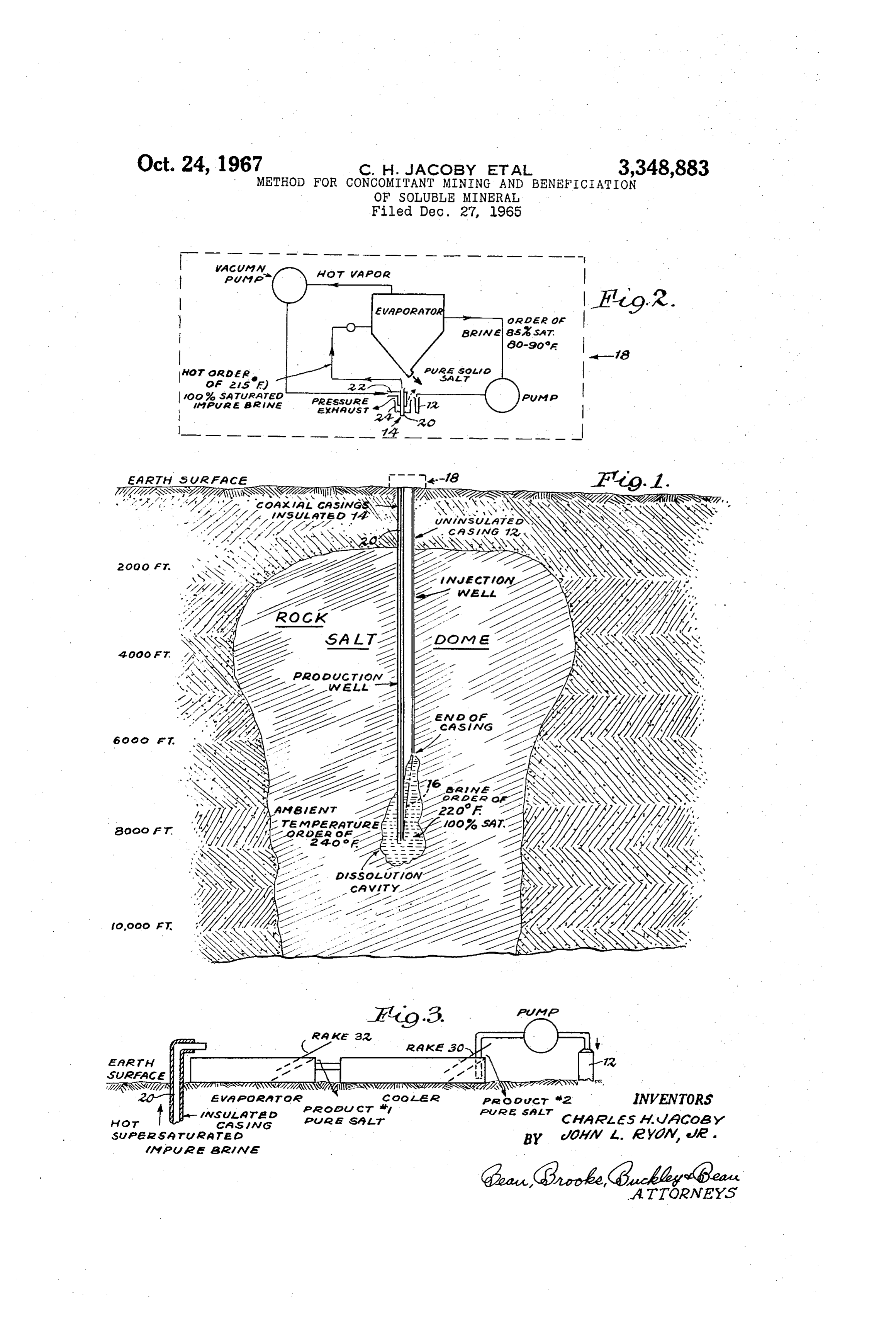
Another object is to provide an improved system as as is well known in the art. Note that the borehole 14. aforesaid which reduces or eliminates the need for ex may preferably be fitted with a casing system of the con ternal heat supplies, and which also greatly reduces the centric triple casing type, for purposes to be explained processing apparati required, compared to prior art sys more fully hereinafter. In any case the boreholes are tems. drilled into the salt deposit so that at their nether or Another object is to provide an improved system as lower ends they penetrate into the deposit at some dis aforesaid wherein a deposit of rock salt or the like is tance apart from one another, say of the order of 200 economically utilized simultaneously as the operational feet or so. Then, to provide for liquid circulation through heat source and as the mineral source for production the system the salt bed between the boreholes is fractured of a purified salt product. O or channeled by some suitable method. For example, Another object is to provide an improved system as as shown in FIG. 1 of the drawing herewith, either one aforesaid effecting great economies in the overall costs of the boreholes may be angularly deflected away from of operation. parallelism with the other borehole as shown at 16 (FIG. Other objects and advantages of the invention will be 1) so as to intercept the other, borehole as it approaches apparent from the following specification and the ac 5 its prescribed depth. Techniques for this purpose are well companying drawing wherein: known, and means therefor are shown for example in FIG. 1 is a phantom-like vertical sectional view, show U.S. Pat. 3,174,549. Or, in lieu thereof the boreholes may be driven straight vertically and parallel, and later ing a geological formation including a typical salt “dome' in process of being mined concomitant with benefication "channeled' together by means of a "fracturing' opera of the mined product in accordance with the present in 20 tion, such as disclosed in U.S. Patent 3,064,957. Thus, in vention. any case the boreholes provided are in fluid-flow com FIG. 2 is an enlarged scale diagrammatic illustration municating relation adjacent their nether or lower ends, of the surface-plant equipment of FIG. 1; and thereby providing a system, wherein solvent may be FIG. 3 is a diagrammatic illustration of another form pumped down one of the boreholes and brine delivered of surface-plant such as may in some cases be employed 25 upwardly through the other to the surface plant. As is in conjunction with the system of the invention. well known in the art, a dissolution cavity as illustrated . As shown by way of example herein, the invention is for example in FIG. 1 will thereupon form in the salt embodied in a system for simultaneously mining and deposit, from which saturated brine may be continuously "purifying' sodium chloride salt occurring in an under pumped to the surface plant which is indicated generally ground deposit of the well known “salt dome” type; but 30 at It18is(FIGS. 1, 2).
a particular feature of the present invention that it is to be understood that the invention may be usefully the system thereof employs the vast heat supplies existent applied to other forms of soluble mineral deposits, such as sodium borate, potash, and the like. However, it is at substantial depths in the earth's crust, not only to effect a feature of the invention that the system thereof is par the requisite vaporization and/or brine-evaporation phases of the salt product beneficiation operation; but in addi ticularly adapted for use in connection with mineral deposits occurring at relatively great depths below the tion to heat the solvent (comprising the residual brine earth surface, employing as an incident thereto the ever effluent from the evaporation operation plus make-up available heat supply inherently existent at deep levels fresh solvent added if and when needed) as it is injected through the casing 12 into the dissolution cavity, thereby underground. For example, it is now known that in the
Louisiana region commercially important “domes” of salt 40 causing it to be delivered into the cavity in undersaturated typically occur as illustrated at FIG. 1 of the drawing condition. By circulating this undersaturated solvent mix herewith; such domes measuring as much as a mile in ture into the dissolution cavity and from thence back to diameter and extending downwardly to as yet unknown the surface and through the salt recovery facility, under. distances, although it is well established that such domes the specifically controlled conditions of the present inven do extend for as much as three to four miles in depth. tion as will be explained hereinafter, the salt deposit per Furthermore, it is known that underground temperatures se provides at the same time the source of raw mineral invariably increase with depth, and that in the salt domes and the source of heat which is also required in connec referred to temperatures of the order of 240 degrees F. tion with the purification process. When the system is in have been recorded at depths of the order of 8,000 feet. stalled and operated within the specific parameters of the It is of course well known that “solution mining” 50 invention the heat so derived will be so conserved and methods are quite practical, and that sodium chloride utilized as to render the system in every way practicable; salt may be taken into solution in situ by circulating water the abstraction of heat from the salt deposit being auto therethrough as by means of underground coalesced bore matically compensated by continuous heat conduction re holes carrying solvent to and brine away from the deposit placements from the ambient geology. for Subsequent evaporation into solid salt form. The 55 Whereas the brine delivery or "production well' casing boreholes may be interconnected by any suitable method, portion of the system is shown herein by way of example Such as by fracturing, trumping, drilling, solution chan to be of the triple casing type including concentrically nelling; or the like. The present invention takes advantage arranged tubes 20, 22, 24, the system may be of any other of the fact that deposits of salt such as illustrated herein preferred form. In any case, a primary (inner) conduit. are at such depths that the earth temperatures ambient 60 or tube 20 is provided to convey the brine in heat-in to a borehole leading downwardly from the surface and sulated form upwardly to the point of discharge of the penetrating such a deposit are of high order, and may brine into the evaporator portion of the brine treating effectively satisfy the heat source requirements for a coin apparatus. Thus, the heated saturated brine derived from cident beneficiation operation when employing apparatus the dissolution cavity will be maintained under maximum of the present invention. Hence, the expense of externally 65 pressure and temperature conditions until delivery to the supplied heat is avoided, and also by virtue of this fea "evaporator,” thereby preventing premature crystalliza ture of the invention the "surface plant' equipment re tion of solids in the conduit system. quirements are reduced, whereby further substantial Any suitable means may be employed for insulating the economies are also effected. brine upflow conduit 20 such as by covering it with heat By way of more specific explanation of the invention, insulation material, or by enclosing it within a larger con as shown herein by way of example a salt dome or other duit 22 and filling the annular space therebetween with deposit is intersected by a pair of vertical boreholes as some suitable heat insulating substance; dead air; vacuum indicated generally at 12-14 respectively. To "complete' or the like. Or, as shown in the drawing herewith at the boreholes and to prevent compression failures of the circuit FIGS. 1, 2, when the purification system is of the closed walls thereof, they will of course be preferably "cased' 75 type the hot vapors from the evaporator apparatus
Page 4
may be advantageously employed by pumping them down might in turn create problems concerning nearby water inside the conduit 22 in heat-exchange relation with the shed pollution, or the like.
brine upflow conduit 20, as shown in better detail in It is also particularly noteworthy that in the case of FIG. 2. Also, as shown in FIG. 2, if the vapor heating the present invention the phenomenon known as the "in system for the brine upflow conduit is employed it may verse solubility ratios' of sodium chloride and calcium be desirable to provide a pressure relief means for the sulphate (the major impurity ingredient of native rock underground system, and this may be readily arranged by salt) operates within the dissolution cavity of the system. providing the third casing 24 as shown in FIG. 2. Note Otherwise stated, because the solvent liquid in the cavity that the upper end of the vent casing 24 is open to the is maintained at high temperature it automatically re atmosphere. In such cases the two outermost casings 22, 10 tards dissolution of calcium sulphate into the brine. 24, will preferably be closed at their lower ends (but in Therefore large percentages of this material when re fluid flow intercommunication thereat) while the inner leased in situ from the salt deposit will simply settle most or central casing 20 will be open at its bottom end down into the bottom of the dissolution cavity, thereby and in communication with the solution cavity. reducing the impurity separation load on the surface It is to be understood that the system of the invention 15 plant. In fact, by virtue of this feature of the invention may employ any preferred form of salt purifying appara the surface refining plant requirements may well be so tus. For example, as shown in FIG. 2 herewith it may reduced that a rudimentary form of solid salt recovery be of a relatively simple, single stage, "evaporator' type apparatus may be satisfactorily employed at the surface, wherein the heated saturated brine is discharged into an such as shown as example at FIG. 3. In this case the evaporator (as disclosed for example in U.S. Patents brine uplift conduit 20 is arranged to simply spray the 2,555,340 and 2,876,182) wherein the brine is subjected superheated saturated brine into an open vat or pan, to pressure and temperature drop conditions permitting whereupon the accompanying release of pressure and pure solid salt to separate out from the brine. However it drop of temperature will result in vaporization of some is to be understood that in lieu of the simple, basic form of the water content and settling out of solid salt. The of refining system shown in FIG. 2 herewith, any other salt carrying brine will then pass over into a cooling vat preferred multi-stage and/or more sophisticated refinery or pan wherein the pure salt of various types and sizes System (such as disclosed in the aforesaid patents) may will recrystallize and settle out at various stations therein be employed. for recovery as by means of rake devices or the like as In any case, the effluent residual brine from the refining shown at 30. Similar devices as indicated at 32 or the like facility, which is being pumped back down the borehole will of course be employed to remove the solid salt prod 12, will be sodium chloride saturated at its injection tem ucts from the evaporator vat, as they accumulate therein. perature (except perhaps whenever evaporation losses re Another feature attendant the mining systems of the quire the addition of "make-up” solvent which may be present invention is that sodium chloride or similar "rock furnished at somewhat lower temperature). However, as salt' deposits of the deep-seated dome type are under explained hereinabove, as this brine travels downwardly such great and constant pressure and temperature con through the uninsulated casing 12 in heat-exchange rela ditions that any cavities formed therein continuously tend tion therewith, it becomes heated, such as by example to close in upon themselves. For example, it has been from an injection temperature of the order of say 90° F. determined that a column of ordinary rock salt will plas up to a temperature of the order of 220 F. as it traverses tically flow and compress to 50% of its original height the dissolution cavity; assuming the cavity ambient rock 40 in 100 hours at 212 F. when subjected to a pressure temperature to be of the order of 240° F. Because the load of 6,000 lbs. per square inch. Thus, assuming initial brine upflow conduit 20 is of heat-insulated form as ex formation of a dissolution cavity at a depth of say 8,000 plained hereinabove, when the superheated (and there feet, the form of such a cavity immediately induces stress fore Supersaturated) brine or solution reaches the evapo concentrations in the wall material in excess of normal rator apparatus it may well be of a temperature in the load forces, thereby insuring continuous plastic flow of order of 215 F.; assuming a reasonable efficiency factor solute to the situs of the dissolution action. for the heat insulating means. The resistance to fluid flow It will, of course, be appreciated that whereas only offered by the extended casing structures will of course a few forms of suitable equipment and operating specifi insure that the dissolution product is also maintained cations have been illustrated and/or discussed by way of under high pressure until it is discharged into the evapo 50 example herein, various changes may be made therein rator apparatus. Hence, it will be appreciated that the without departing from the spirit of the invention or the operative characteristics of the heat-saturator phase of scope of the following claims.
the system of the invention bring it well within the realm We claim:
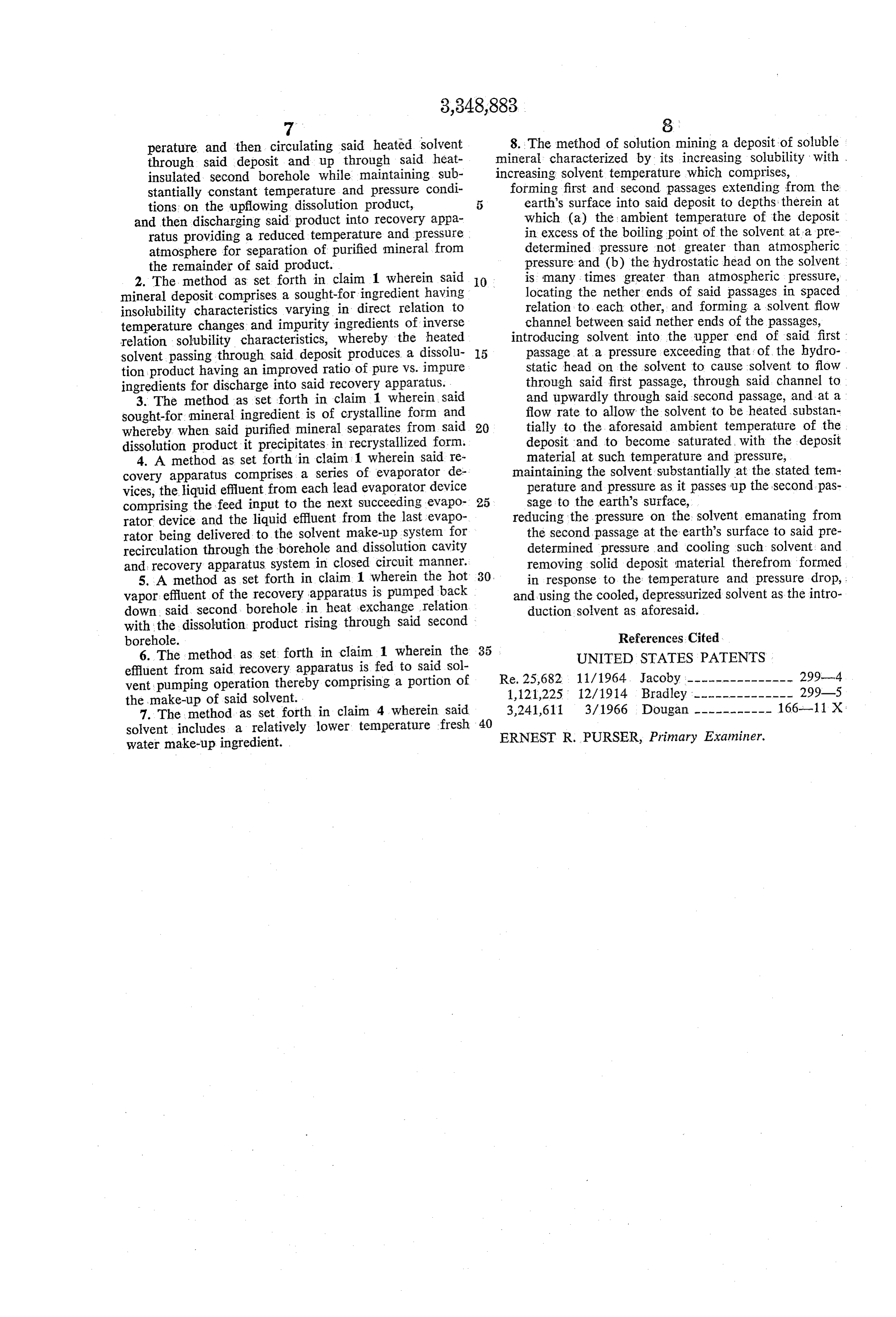
of feasibility for realization of the objects of the inven 1. The method of concomitantly mining and benefici tion as set forth hereinabove. 55 ating a deposit of soluble mineral disposed at such depth However, it is still another technological feature and beneath the earth's surface as to be surrounded by a economic advantage of the present invention that by virtue geological environment characterized by being at a sub of the relative positional arrangements and operative rela stantially elevated temperature relative to the neighbor tionships of the essential components of the system, there hood earth surface rock temperature, said method com may be no longer a need for any externally derived heat 60 prising,
Supply, but also there is no essential need for certain drilling first and second bore holes downwardly from accessory devices such as are called for by prior art sys the earth's surface into said deposit, tems. This feature of the invention derives from the fact completing said boreholes by installation of means pre that insoluble impurities resident in the deposit being venting wall failure closures of said boreholes and mined automatically settle out of the brine when released 65 by installation of wall heat insulation means sub by dissolution of the cavity wall material, and fall into stantially throughout the length of said second bore and remain in the bottom of the cavity, and therefore do hole from the upper end thereof to at least adjacent not carry up into the refining apparatus. Hence, the need the nether end thereof, for filtering equipment is minimized, and the need for sat establishing fluid-flow communication between the urators, condensers, heaters and the like in connection 70 nether ends of said bore holes through said deposit, with the surface plant is completely eliminated. pumping a solvent for said mineral downwardly Also, because in the case of the present invention the through said first bore hole in direct heat exchange insoluble impurities occurring in the mineral deposit are relation with the borehole wall and in indirect heat not brought to the surface, there is no problem at the exchange relation with the ambient geology thereby surface plant with respect to disposal of wastes, such as 75 heating said solvent to a substantially elevated tem
Page 5
perature and then circulating said heated solvent mineral 8. The method of solution mining a deposit of soluble through said deposit and up through said heat characterized by its increasing solubility with insulated second borehole while maintaining sub increasing solvent temperature which comprises, stantially constant temperature and pressure condi forming first and second passages extending from the tions on the upflowing dissolution product, 5 earth's surface into said deposit to depths therein at and then discharging said product into recovery appa which (a) the ambient temperature of the deposit ratus providing a reduced temperature and pressure in excess of the boiling point of the solvent at a pre atmosphere for separation of purified mineral from determined pressure not greater than atmospheric the remainder of said product. pressure and (b) the hydrostatic head on the solvent 2. The method as set forth in claim 1 wherein said 0 is many times greater than atmospheric pressure, mineral deposit comprises a sought-for ingredient having locating the nether ends of said passages in spaced insolubility characteristics varying in direct relation to relation to each other, and forming a solvent flow temperature changes and impurity ingredients of inverse channel between said nether ends of the passages, relation solubility characteristics, whereby the heated introducing solvent into the upper end of said first solvent passing through said deposit produces a dissolu 5 passage at a pressure exceeding that: of the hydro tion product having an improved ratio of pure vs. impure static head on the solvent to cause solvent to flow . ingredients for discharge into said recovery apparatus. through said first passage, through said channel to 3. The method as set forth in claim 1 wherein said and upwardly through said second passage, and at a sought-for mineral ingredient is of crystalline form and flow rate to allow the solvent to be heated substan whereby when said purified mineral separates from said 20 tially to the aforesaid ambient temperature of the dissolution product it precipitates in recrystallized form. deposit and to become saturated, with the deposit 4. A method as set forth in claim 1 wherein said re material at such temperature and pressure, covery apparatus comprises a series of evaporator de maintaining the solvent substantially at the stated tem vices, the liquid effluent from each lead evaporator device perature and pressure as it passes up the second pas comprising the feed input to the next Succeeding evapo 25 sage to the earth's surface, rator device and the liquid effluent from the last evapo reducing the pressure on the solvent emanating from rator being delivered to the solvent make-up System for the second passage at the earth's surface to said pre recirculation through the borehole and dissolution cavity determined pressure and cooling such solvent and and recovery apparatus system in closed circuit manner. removing solid deposit material therefrom formed 5. A method as set forth in claim 1 wherein the hot 30 in response to the temperature and pressure drop, vapor effluent of the recovery apparatus is pumped back and using the cooled, depressurized solvent as the intro down said second borehole in heat eXchange relation duction solvent as aforesaid. with the dissolution product rising through said second borehole. References. Cited 6. The method as set forth in claim 1 wherein the 35 UNITED STATES PATENTS effluent from said recovery apparatus is fed to said Sol Re. 25,682 11/1964. Jacoby --------------- 299-4 vent pumping operation thereby comprising a portion of 1,121,225 12/1914 Bradley -------------- 299-5 the make-up of said solvent. 3,241,611 3/1966 Dougan ----------- 166-11 X: 7. The method as set forth in claim 4 wherein said solvent includes a relatively lower temperature fresh - 40 water make-up ingredient. , ERNEST R. PURSER, Primary Examiner.
Page 6
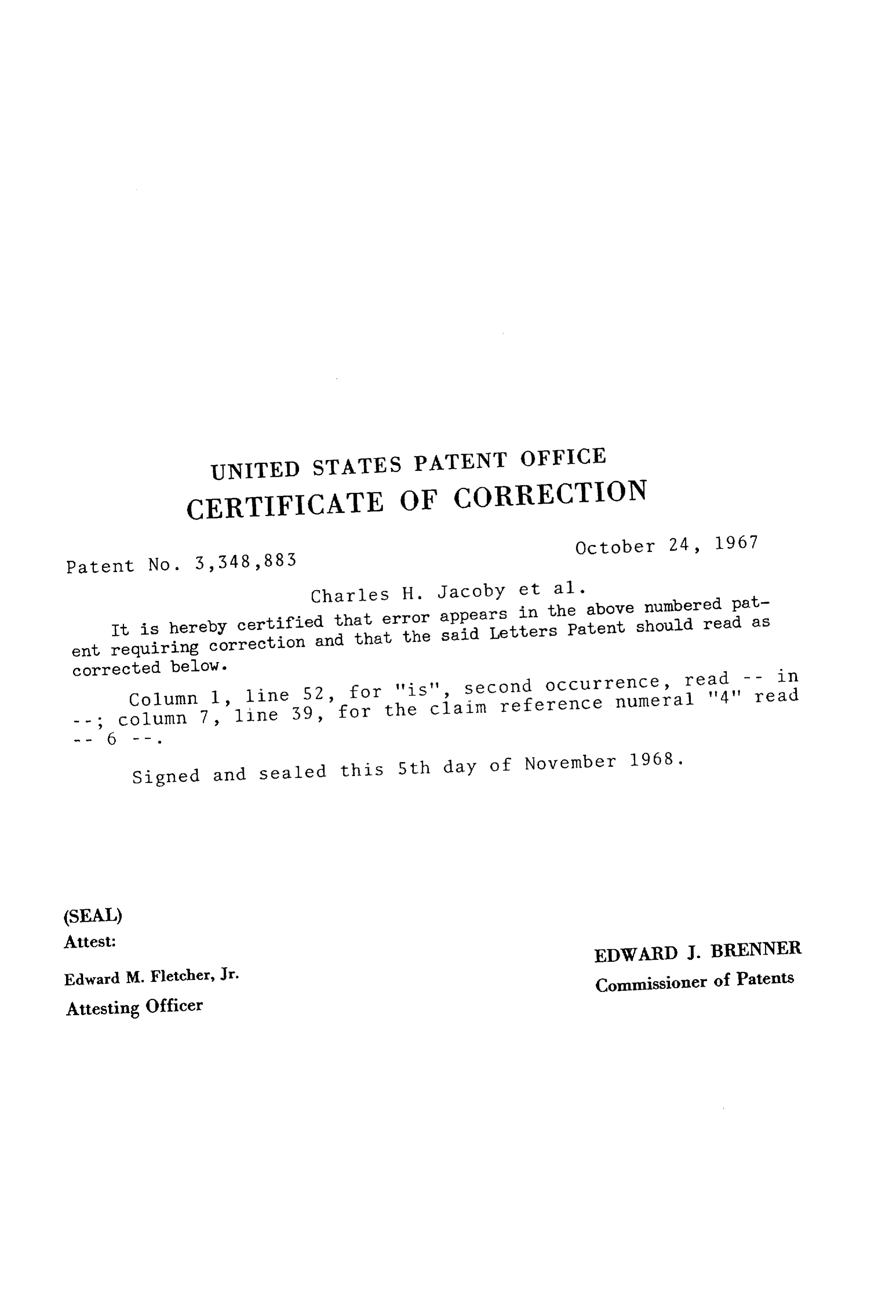
UNITED STATES PATENT OFFICE
CERTIFICATE OF CORRECTION
Patent No. 3,348,883 October 24, 1967 Charles H. Jacoby et al.
It is hereby certified that error appears in the above numbered pat ent requiring correction and that the said Letters Patent should read as corrected below.
Column 1, line 52, for "is", second occurrence, read -- in column 7, line 39, for the claim reference numeral '4' read Signed and Sealed this 5th day of November 1968.
(SEAL)
Attest:
Edward M. Fletcher, Jr. EDWARD J. BRENNER Attesting Officer Commissioner of Patents
Provenance
- Collection
- Cited prior art
- Original PDF
- patentimages.storage.googleapis.com →
- Filed
- 1965-12-27
- Pages
- 6
- Method
- pdftotext (the PDF's own text layer) + pdftoppm 300dpi page scans
- Source
- Google Patents bibliographic record
- Granted
- 1967-10-24
- Inventors
- Charles H Jacoby; Jr John L Ryon; International Salt Co
- Transcribed from
- patentimages.storage.googleapis.com →