patent · US3653429
Water heating system
4 April 1972
Page 1 — bibliographic record
United States Patent 15) 3,653,429 Lawrence (45) Apr. 4, 1972 54 WATER HEATING SYSTEM 3,382,917 5/1968 Rice................................... 165/107 X 3,382,919 5/1968. Rice....................................... 165/105 72) Inventor: Willis Thompson Lawrence, Winchester,
Mass. Primary Examiner-Edward J. Michael 73) Assignee: Hooker Chemical Corporation, Niagara Attorney-Peter F. Casella, Donald C. Studley and Richard K. Falls, N.Y. Jackson 22 Filed: May 6, 1969 57 ABSTRACT (21) Appl. No.: 822,243 Several heat storage modules may be connected by manifold means to one or more water holding tanks. The heat storage 52 U.S. Cl................................................... 165/1, 165/107 modules may be connected either in parallel or series to water I51) Int. Cl.......................................................... F28d 15/00 holding tanks. A single water holding tank may be employed 58 Field of Search.............................. 237/1,56, 81; 60/26; in which a separate condenser is provided for each heat 165/105-107 storage module or in which a common condenser is employed within the water holding tank. Furthermore, several heat (56) References Cited storage modules may be connected in series to a single water holding tank. The provision of several heat storage modules in
UNITED STATES PATENTS conjunction with one or more water holding tanks effects a more dependable water heating system by providing larger 1,002,768 9/1911 Shuman... ...60/26 heat storage capacity, more constant heat delivery over a 1,069,949 8/1913 Hassler....... ...219/70 given period of time, and more convenient unit size. 2,933,885 4/1960 Benedek.................................... 60/26 3,033,538 5/1962 Iddles et al......................... 165/107 X 4 Claims, 4 Drawing Figures
Page 2
Drawing sheet — no readable text.
Page 3
Drawing sheet — no readable text.
Page 4
Drawing sheet — no readable text.
Page 5
Drawing sheet — no readable text.
Page 6
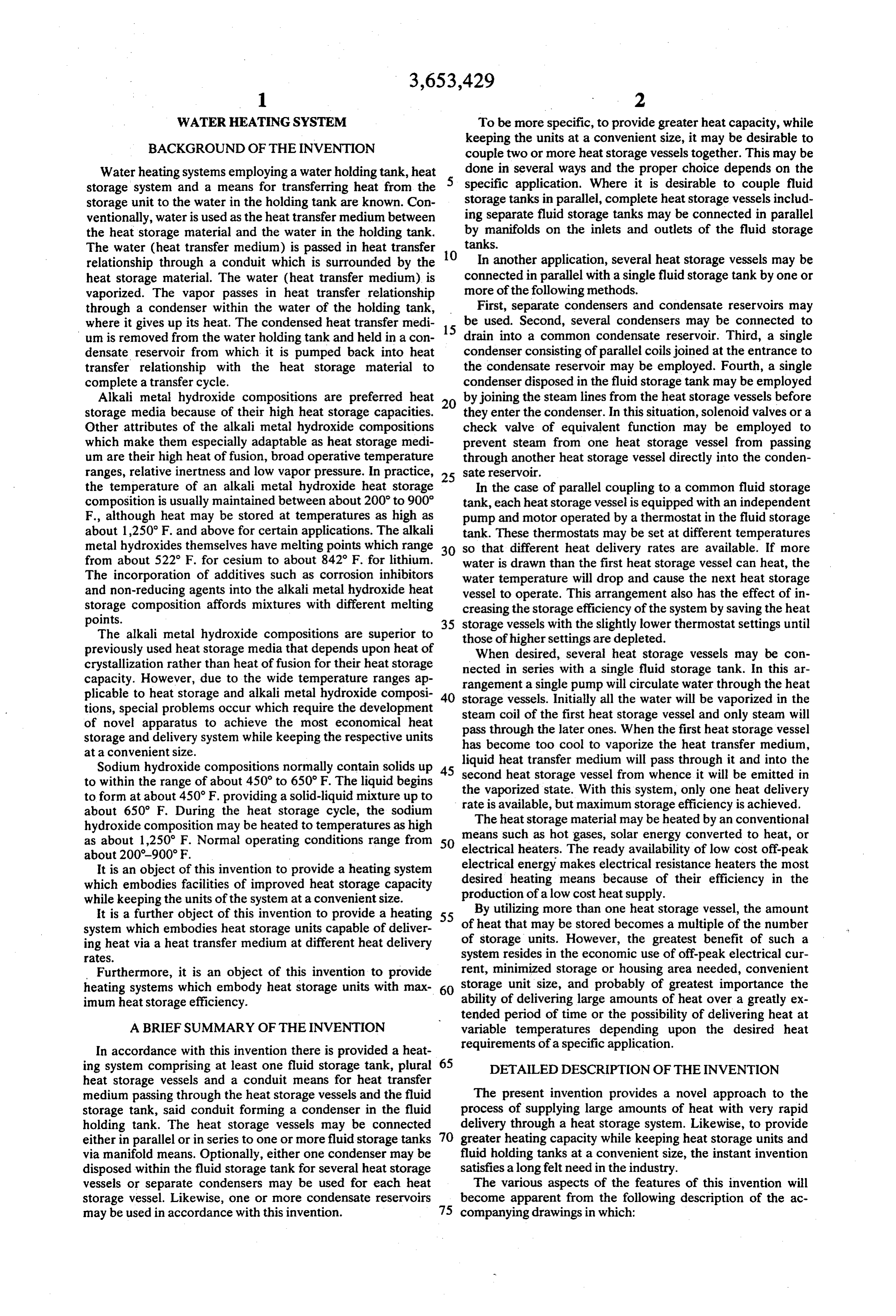
WATER HEATENG SYSTEM To be more specific, to provide greater heat capacity, while
BACKGROUND OF THE INVENTION
keeping the units at a convenient size, it may be desirable to couple two or more heat storage vessels together. This may be
Water heating systems employing a water holding tank, heat done in several ways and the proper choice depends on the storage system and a means for transferring heat from the specific application. Where it is desirable to couple fluid storage unit to the water in the holding tank are known. Con storage tanks in parallel, complete heat storage vessels includ ventionally, water is used as the heat transfer medium between ing separate fluid storage tanks may be connected in parallel the heat storage material and the water in the holding tank. by manifolds on the inlets and outlets of the fluid storage The water (heat transfer medium) is passed in heat transfer 10 tanks.
relationship through a conduit which is surrounded by the In another application, several heat storage vessels may be heat storage material. The water (heat transfer medium) is connected in parallel with a single fluid storage tank by one or vaporized. The vapor passes in heat transfer relationship more of the following methods.
through a condenser within the water of the holding tank, First, separate condensers and condensate reservoirs may where it gives up its heat. The condensed heat transfer medi 15 be used. Second, several condensers may be connected to um is removed from the water holding tank and held in a con drain into a common condensate reservoir. Third, a single densate reservoir from which it is pumped back into heat condenser consisting of parallel coils joined at the entrance to transfer relationship with the heat storage material to the condensate reservoir may be employed. Fourth, a single complete a transfer cycle. condenser disposed in the fluid storage tank may be employed Alkali metal hydroxide compositions are preferred heat by joining the steam lines from the heat storage vessels before storage media because of their high heat storage capacities. 20 they enter the condenser. In this situation, solenoid valves or a Other attributes of the alkali metal hydroxide compositions check valve of equivalent function may be employed to which make them especially adaptable as heat storage medi prevent steam from one heat storage vessel from passing um are their high heat of fusion, broad operative temperature through another heat storage vessel directly into the conden ranges, relative inertness and low vapor pressure. In practice, 25 sate reservoir.
the temperature of an alkali metal hydroxide heat storage In the case of parallel coupling to a common fluid storage composition is usually maintained between about 200 to 900 tank, each heat storage vessel is equipped with an independent F., although heat may be stored at temperatures as high as pump and motor operated by a thermostat in the fluid storage about 1,250 F. and above for certain applications. The alkali tank. These thermostats may be set at different temperatures metal hydroxides themselves have melting points which range 30 so that different heat delivery rates are available. If more from about 522 F. for cesium to about 842 F. for lithium. water is drawn than the first heat storage vessel can heat, the The incorporation of additives such as corrosion inhibitors water temperature will drop and cause the next heat storage and non-reducing agents into the alkali metal hydroxide heat vessel to operate. This arrangement also has the effect of in storage composition affords mixtures with different melting creasing the storage efficiency of the system by saving the heat points. 35 storage vessels with the slightly lower thermostat settings until The alkali metal hydroxide compositions are superior to those of higher settings are depleted. previously used heat storage media that depends upon heat of When desired, several heat storage vessels may be con crystallization rather than heat of fusion for their heat storage nected in series with a single fluid storage tank. In this ar capacity. However, due to the wide temperature ranges ap rangement a single pump will circulate water through the heat plicable to heat storage and alkali metal hydroxide composi 40 storage vessels. Initially all the water will be vaporized in the tions, special problems occur which require the development steam coil of the first heat storage vessel and only steam will of novel apparatus to achieve the most economical heat storage and delivery system while keeping the respective units pass through the later ones. When the first heat storage vessel has become too cool to vaporize the heat transfer medium, at a convenientsize.
Sodium hydroxide compositions normally contain solids up 45 liquid heat transfer medium will pass through it and into the to within the range of about 450 to 650 F. The liquid begins second heat storage vessel from whence it will be emitted in to form at about 450°F. providing a solid-liquid mixture up to the vaporized state. With this system, only one heat delivery rate is available, but maximum storage efficiency is achieved.
about 650 F. During the heat storage cycle, the sodium The heat storage material may be heated by an conventional hydroxide composition may be heated to temperatures as high means such as hot gases, solar energy converted to heat, or as about 1,250 F. Normal operating conditions range from 50 electrical heaters. The ready availability of low cost off-peak
It is an object of this invention to provide a heating system electrical energy makes electrical resistance heaters the most which embodies facilities of improved heat storage capacity desired heating means because of their efficiency in the production of a low cost heat supply.
while keeping the units of the system at a convenientsize.
It is a further object of this invention to provide a heating 55 By utilizing more than one heat storage vessel, the amount system which embodies heat storage units capable of deliver of heat that may be stored becomes a multiple of the number ing heat via a heat transfer medium at different heat delivery of storage units. However, the greatest benefit of such a rates. system resides in the economic use of off-peak electrical cur Furthermore, it is an object of this invention to provide rent, minimized storage or housing area needed, convenient heating systems which embody heat storage units with max 60 storage unit size, and probably of greatest importance the imum heat storage efficiency. ability of delivering large amounts of heat over a greatly ex tended period of time or the possibility of delivering heat at
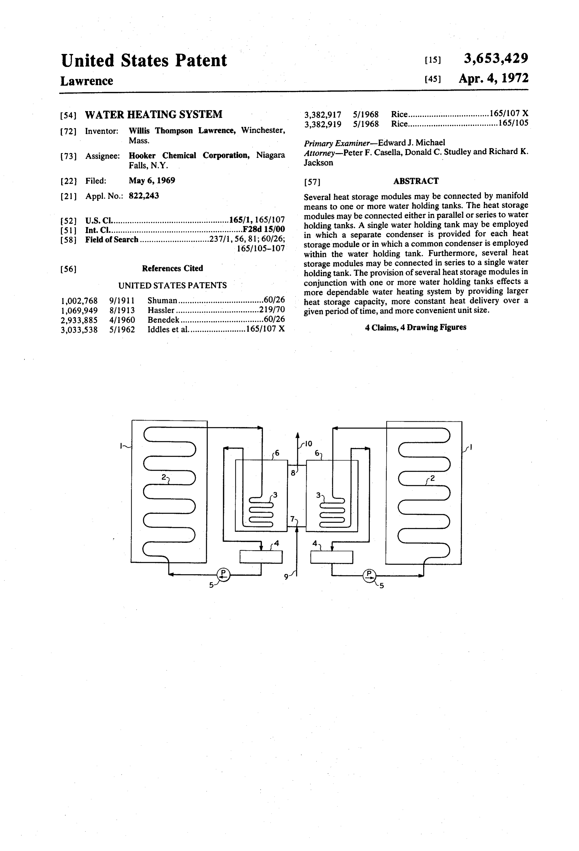
A BRIEFSUMMARY OF THE INVENTION variable temperatures depending upon the desired heat In accordance with this invention there is provided a heat requirements of a specific application. ing system comprising at least one fluid storage tank, plural 65 DETAILED DESCRIPTION OF THE INVENTION heat storage vessels and a conduit means for heat transfer medium passing through the heat storage vessels and the fluid The present invention provides a novel approach to the storage tank, said conduit forming a condenser in the fluid process of supplying large amounts of heat with very rapid holding tank. The heat storage vessels may be connected delivery through a heat storage system. Likewise, to provide either in parallel or in series to one or more fluid storage tanks 70 greater heating capacity while keeping heat storage units and via manifold means. Optionally, either one condenser may be fluid holding tanks at a convenient size, the instant invention disposed within the fluid storage tank for several heat storage satisfies along felt need in the industry. vessels or separate condensers may be used for each heat The various aspects of the features of this invention will storage vessel. Likewise, one or more condensate reservoirs become apparent from the following description of the ac may be used in accordance with this invention. 75 companying drawings in which:
Page 7
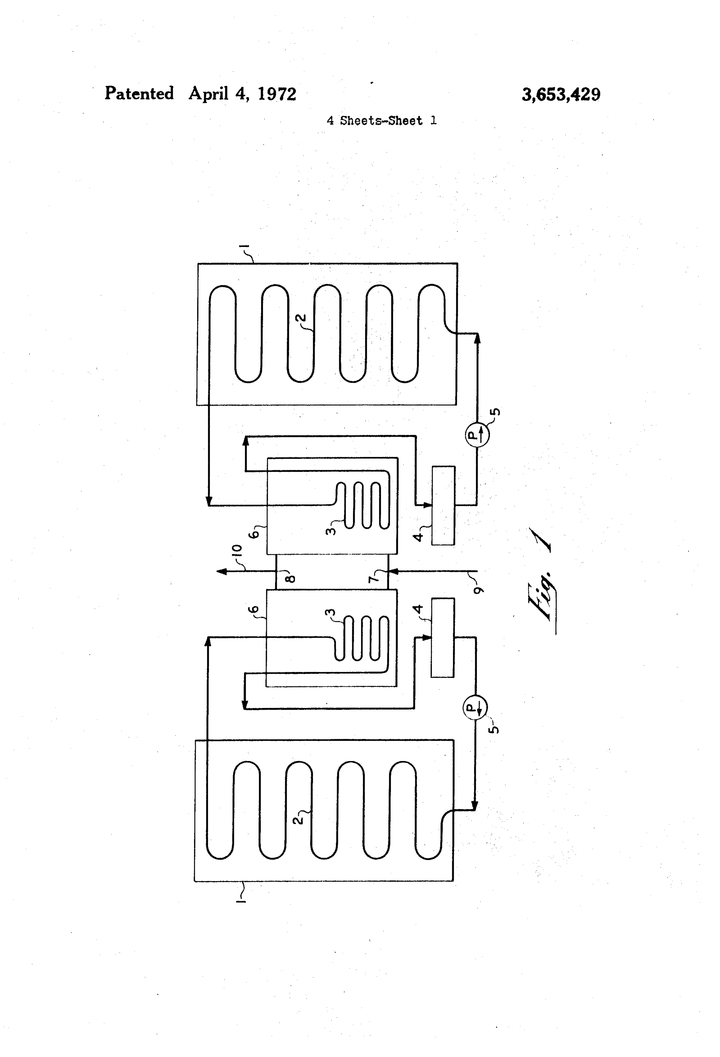
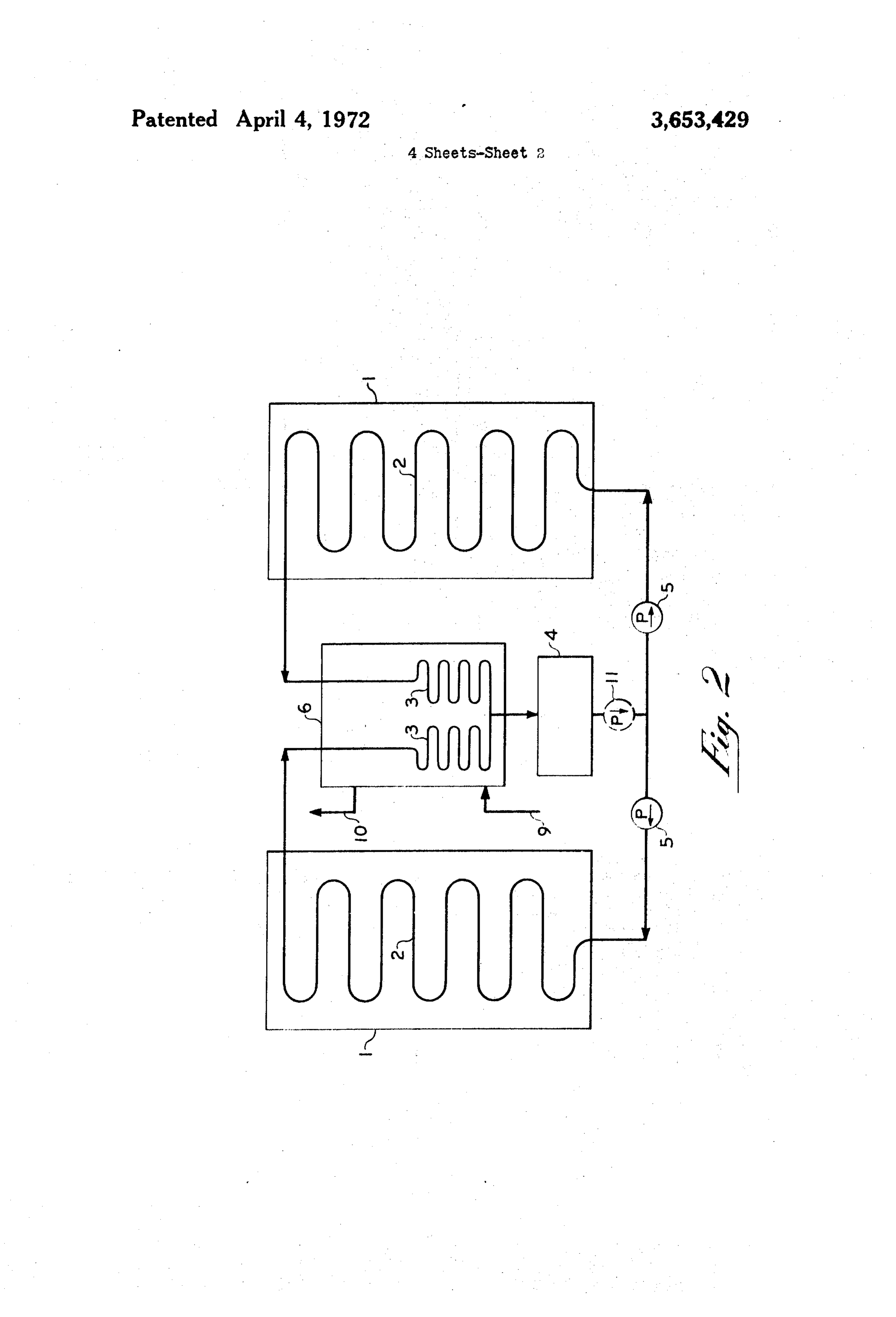
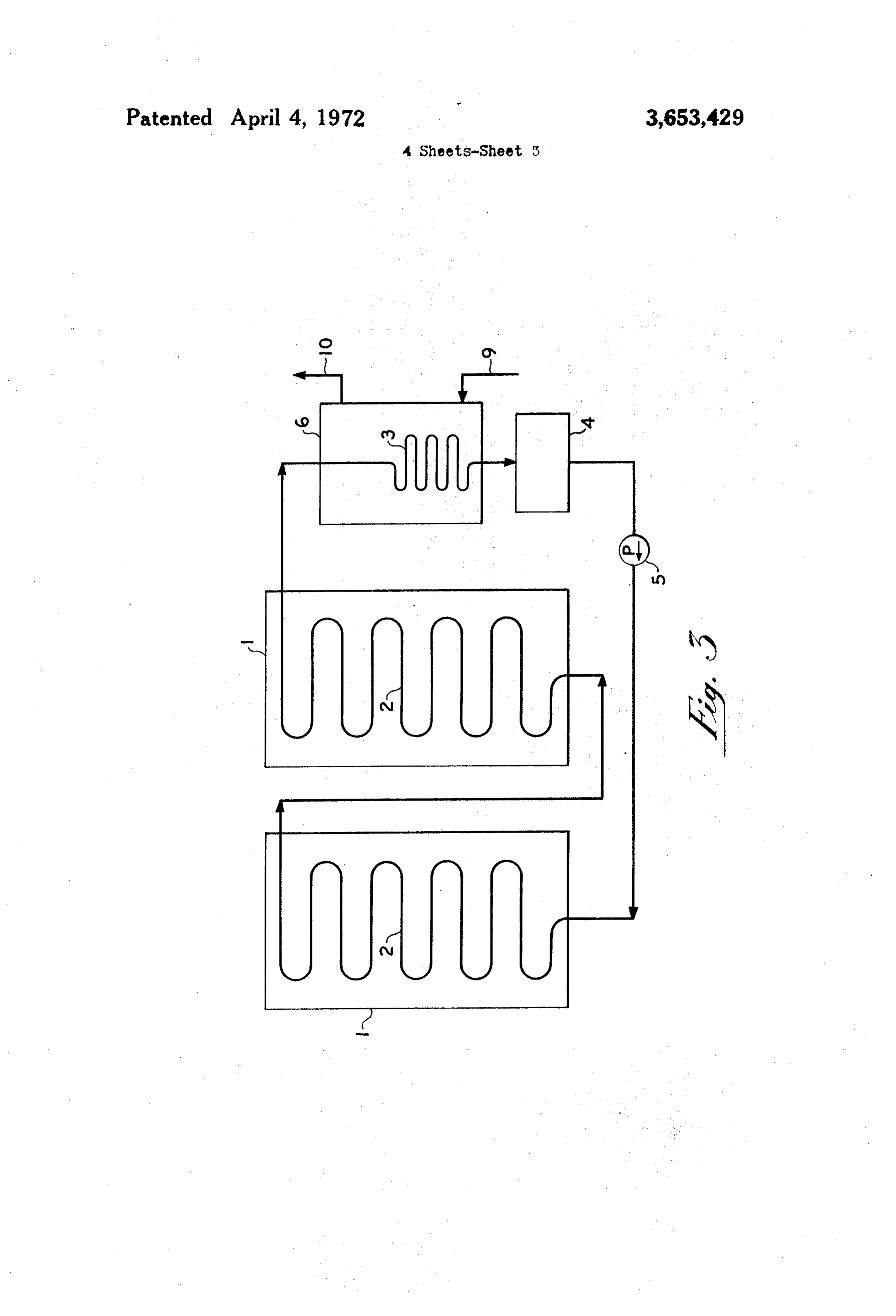
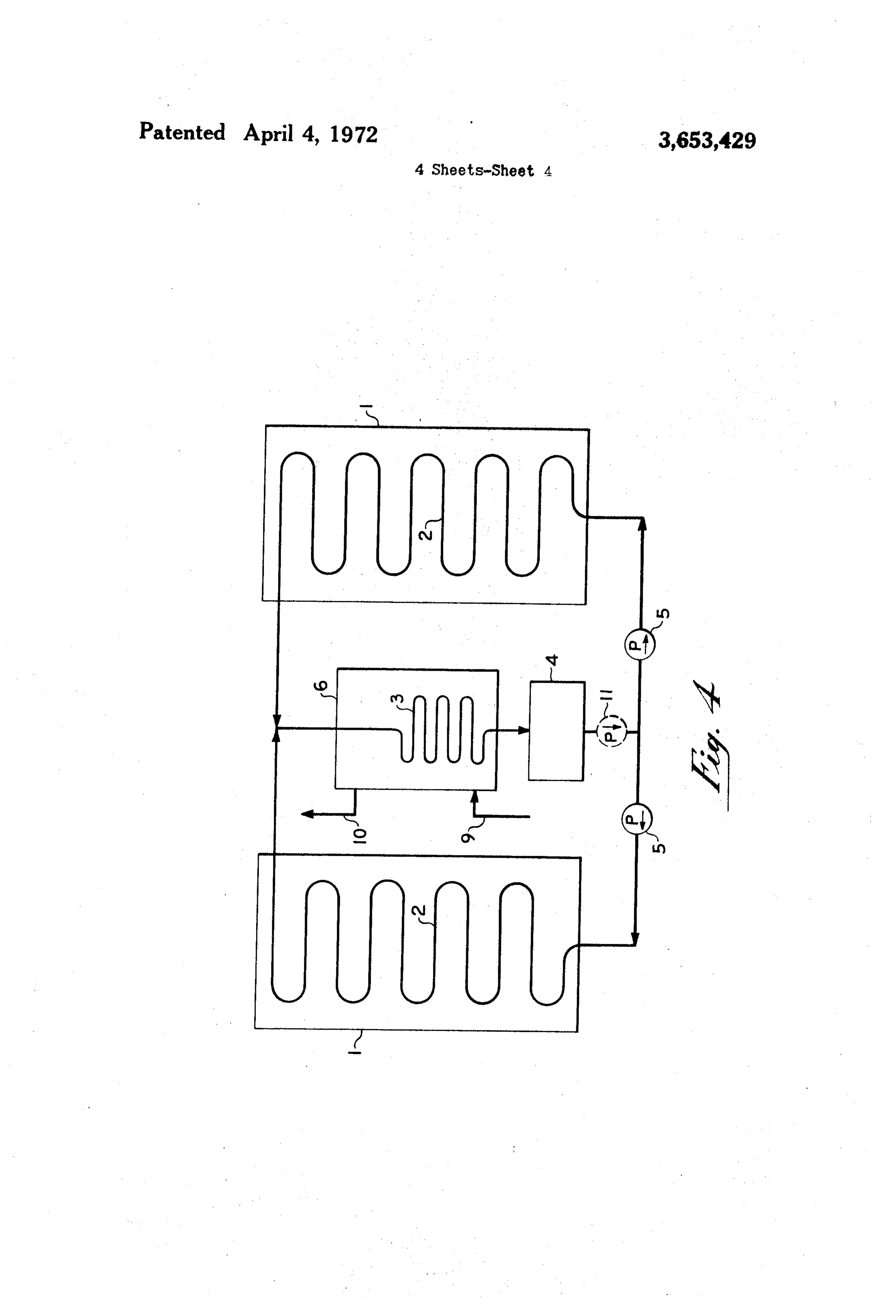
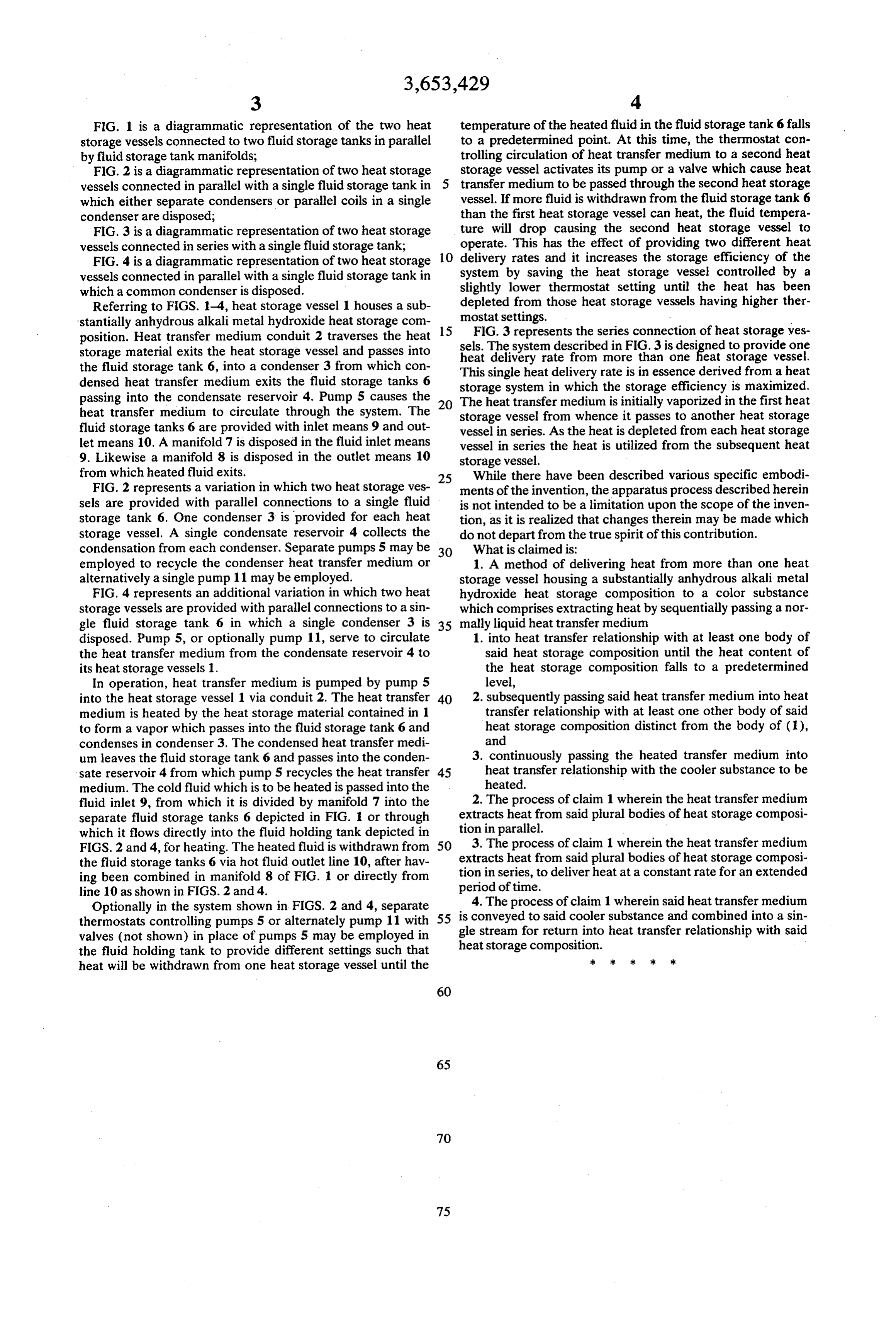
FIG. 1 is a diagrammatic representation of the two heat temperature of the heated fluid in the fluid storage tank 6 falls storage vessels connected to two fluid storage tanks in parallel to a predetermined point. At this time, the thermostat con by fluid storage tank manifolds; trolling circulation of heat transfer medium to a second heat FIG. 2 is a diagrammatic representation of two heat storage storage vessel activates its pump or a valve which cause heat vessels connected in parallel with a single fluid storage tank in transfer medium to be passed through the second heat storage which either separate condensers or parallel coils in a single vessel. If more fluid is withdrawn from the fluid storage tank 6 condenser are disposed; than the first heat storage vessel can heat, the fluid tempera FIG. 3 is a diagrammatic representation of two heat storage ture will drop causing the second heat storage vessel to vessels connected in series with a single fluid storage tank; operate. This has the effect of providing two different heat FIG. 4 is a diagrammatic representation of two heat storage 10 delivery rates and it increases the storage efficiency of the vessels connected in parallel with a single fluid storage tank in system by saving the heat storage vessel controlled by a which a common condenser is disposed. slightly lower thermostat setting until the heat has been Referring to FIGS. 1-4, heat storage vessel 1 houses a sub depleted from those heat storage vessels having higher ther 'stantially anhydrous alkali metal hydroxide heat storage com 15 mostat settings.
position. Heat transfer medium conduit 2 traverses the heat sels.FIG.3 represents the series connection of heat storage ves The system described in FIG.3 is designed to provide one storage material exits the heat storage vessel and passes into heat delivery rate from more than one heat storage vessel. the fluid storage tank 6, into a condenser 3 from which con This single heat delivery rate is in essence derived from a heat densed heat transfer medium exits the fluid storage tanks 6 storage system in which the storage efficiency is maximized. passing into the condensate reservoir 4. Pump 5 causes the The heat transfer medium is initially vaporized in the first heat heat transfer medium to circulate through the system. The storage vessel from whence it passes to another heat storage fluid storage tanks 6 are provided with inlet means 9 and out vessel in series. As the heat is depleted from each heat storage let means 10. A manifold 7 is disposed in the fluid inlet means vessel in series the heat is utilized from the subsequent heat 9. Likewise a manifold 8 is disposed in the outlet means 10 storage vessel.
from which heated fluid exits. 25 While there have been described various specific embodi FIG. 2 represents a variation in which two heat storage ves ments of the invention, the apparatus process described herein sels are provided with parallel connections to a single fluid is not intended to be a limitation upon the scope of the inven storage tank 6. One condenser 3 is provided for each heat tion, as it is realized that changes therein may be made which storage vessel. A single condensate reservoir 4 collects the do not depart from the true spirit of this contribution. condensation from each condenser. Separate pumps 5 may be 30 What is claimed is:
employed to recycle the condenser heat transfer medium or 1. A method of delivering heat from more than one heat alternatively a single pump 11 may be employed. storage vessel housing a substantially anhydrous alkali metal FIG. 4 represents an additional variation in which two heat hydroxide heat storage composition to a color substance storage vessels are provided with parallel connections to a sin which comprises extracting heat by sequentially passing a nor gle fluid storage tank 6 in which a single condenser 3 is 35 mally liquid heat transfer medium disposed. Pump 5, or optionally pump 11, serve to circulate 1. into heat transfer relationship with at least one body of the heat transfer medium from the condensate reservoir 4 to said heat storage composition until the heat content of its heat storage vessels 1. the heat storage composition falls to a predetermined In operation, heat transfer medium is pumped by pump 5 level, into the heat storage vessel 1 via conduit 2. The heat transfer 40 2. subsequently passing said heat transfer medium into heat medium is heated by the heat storage material contained in 1 transfer relationship with at least one other body of said to form a vapor which passes into the fluid storage tank 6 and heat storage composition distinct from the body of (1), condenses in condenser 3. The condensed heat transfer medi and um leaves the fluid storage tank 6 and passes into the conden 3. continuously passing the heated transfer medium into sate reservoir 4 from which pump 5 recycles the heat transfer 45 heat transfer relationship with the cooler substance to be medium. The cold fluid which is to be heated is passed into the heated.
fluid inlet 9, from which it is divided by manifold 7 into the 2. The process of claim 1 wherein the heat transfer medium separate fluid storage tanks 6 depicted in FIG. 1 or through extracts heat from said plural bodies of heat storage composi which it flows directly into the fluid holding tank depicted in tion in parallel.
FIGS. 2 and 4, for heating. The heated fluid is withdrawn from 50 3. The process of claim 1 wherein the heat transfer medium the fluid storage tanks 6 via hot fluid outlet line 10, after hav extracts heat from said plural bodies of heat storage composi ing been combined in manifold 8 of FIG. 1 or directly from tion in series, to deliver heat at a constant rate for an extended line 10 as shown in FIGS. 2 and 4. period of time.
Optionally in the system shown in FIGS. 2 and 4, separate 4. The process of claim 1 wherein said heat transfer medium thermostats controlling pumps 5 or alternately pump 11 with 55 is conveyed to said cooler substance and combined into a sin valves (not shown) in place of pumps 5 may be employed in gle stream for return into heat transfer relationship with said the fluid holding tank to provide different settings such that heat storage composition.
heat will be withdrawn from one heat storage vessel until the
Page 8
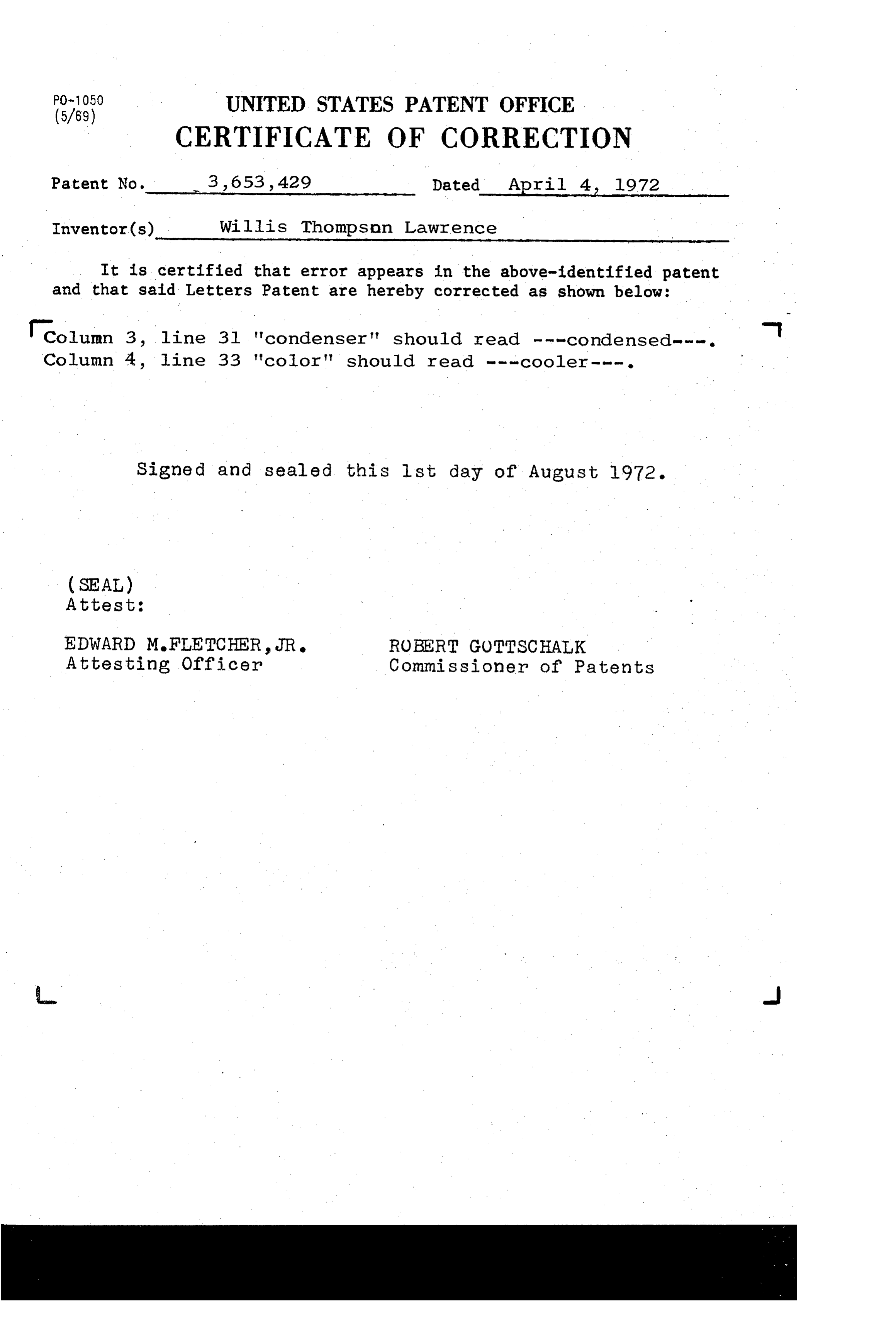
PO-1050 UNITED STATES PATENT OFFICE
CERTIFICATE OF CORRECTION
Patent No. 3, 653,429 Dated April 4, 1972 - Inventor(s) Willis Thompson Lawrence
It is certified that error appears in the above-identified patent and that said Letters Patent are hereby corrected as shown below:
column 3, line 3l 'condenser' should read - - -condensed---. Column 4, line 33 'color" should read - - -cooler ---.
Signed and sealed this list day of August l972.
(SEAL)
Attest:
EDWARD M.FLETCHER, JR. ROBERT GOTTSCHALK
Attesting Officer Commissioner of Patents
Page 9
PO-1050 UNITED STATES PATENT OFFICE
CERTIFICATE OF CORRECTION
Inventor(s) Willis Thompson Lawrence
It is certified that error appears in the above-identified patent and that said Letters Patent are hereby corrected as shown below:
column 3, line 3l "condenser' should read - - -condensed---. - Column 4, line 33 'color" should read - - -cooler ---.
Signed and sealed this list day of August l972.
(SEAL)
Attest:
EDWARD M.FLETCHER, JR. ROBERT GOTTSCHALK
Attesting Officer Commissioner of Patents
Provenance
- Collection
- Cited prior art
- Original PDF
- patentimages.storage.googleapis.com →
- Filed
- 1969-05-06
- Pages
- 9
- Method
- pdftotext (the PDF's own text layer) + pdftoppm 300dpi page scans
- Source
- Google Patents bibliographic record
- Granted
- 1972-04-04
- Inventors
- Willis Thompson Lawrence; Hooker Chemical Corp
- Transcribed from
- patentimages.storage.googleapis.com →