patent · US4083701
Process and apparatus for removing undesirable gases from flue gases
11 April 1978
Page 1 — bibliographic record
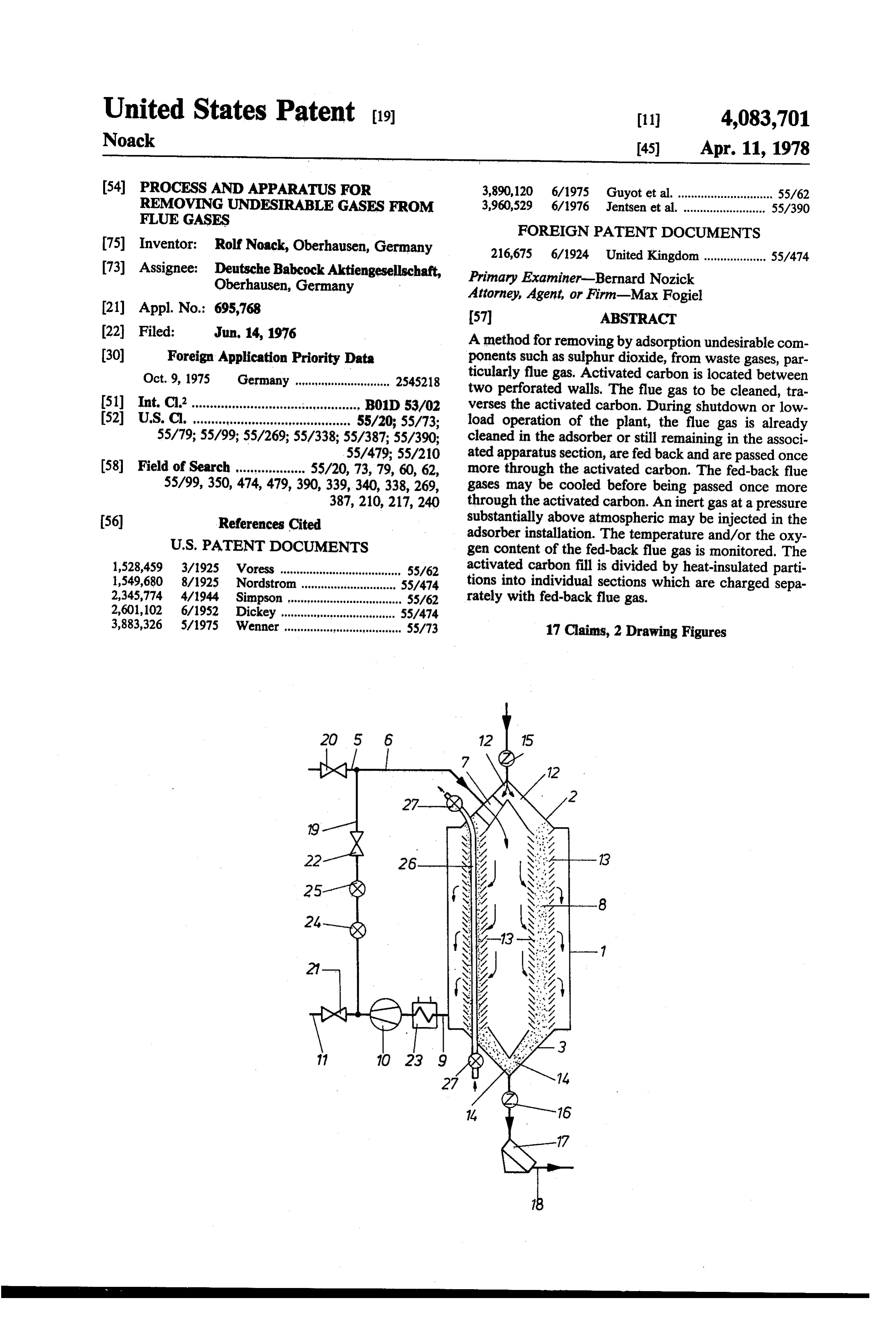
United States Patent (19) 11 4,083,701 Noack 45) Apr. 11, 1978 (54) PROCESS AND APPARATUS FOR 3,890,120 6/1975 Guyot et al. ............................. 55/62 REMOVING UNDESERABLEGASES FROM 3,960,529 6/1976 Jentsen et al. ......................... 55/390
FLUEGASES
FOREIGN PATENT DOCUMENTS
(75) Inventor: Rolf Noack, Oberhausen, Germany 216,675 6/1924 United Kingdom ................... 55/474 (73) Assignee: Deutsche Babcock Aktiengesellschaft, Primary Examiner-Bernard Nozick Oberhausen, Germany Attorney, Agent, or Firm-Max Fogiel (21) Appl. No.: 695,768 57 ABSTRACT 22 Filed: Jun, 14, 1976 A method for removing by adsorption undesirable com (30) Foreign Application Priority Data ponents such as sulphur dioxide, from waste gases, par Oct. 9, 1975 Germany ......................... 2545218 ticularly flue gas. Activated carbon is located between two perforated walls. The flue gas to be cleaned, tra (51) 0 B01D 53/02 verses the activated carbon. During shutdown or low (52) U.S. C. ......... he ep 40 to ee a a woo pops so a one to so see 55/20, 55/73; load operation of the plant, the flue gas is already 55/79;55/99;55/269; 55/338; 55/387;55/390; cleaned in the adsorber or still remaining in the associ 55/479; 55/210 ated apparatus section, are fed back and are passed once 58) Field of Search ................... 55/20, 73,79, 60, 62, more through the activated carbon. The fed-back flue 55/99, 350, 474, 479,390,339,340,338,269, gases may be cooled before being passed once more 387,210, 217, 240 through the activated carbon. An inert gas at a pressure (56) References Cited substantially above atmospheric may be injected in the adsorber installation. The temperature and/or the oxy
1,528,459 3/1925 Voress .....................................
.............. 55/62 activated carbon fill is divided by heat-insulated parti
Nordstrom ... 55/474 tions into individual sections which are charged sepa 2,345,774 4/1944 Simpson .................................. S5/62 rately with fed-back flue gas. 2,601,102 6/1952 Dickey ................................... 55/474 3,883,326 5/1975 Wenner ........................ a days assa a 55/73 17 Claims, 2 Drawing Figures
Page 2
Drawing sheet — no readable text.
Page 3
back flue gases are cooled before being blown through
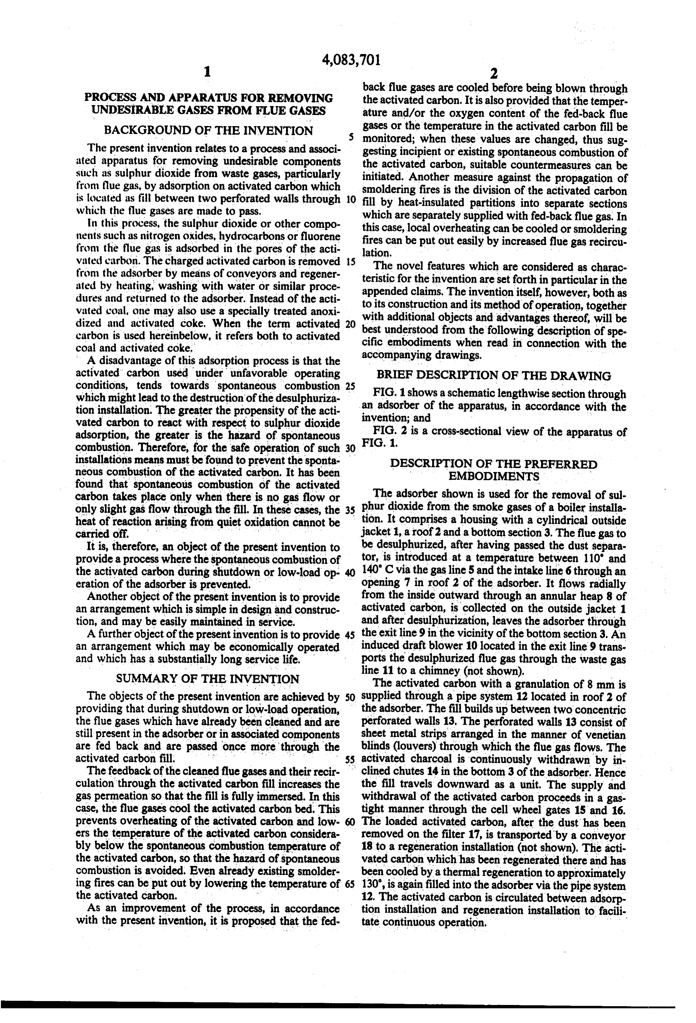
PROCESS AND APPARATUS FOR REMOVING the activated carbon. It is also provided that the temper UNDESERABLE GASES FROM FLUEGASES ature and/or the oxygen content of the fed-back flue BACKGROUND OF THE INVENTION gases or the temperature in the activated carbon fill be The present invention relates to a process and associ monitored; when these values are changed, thus sug gesting incipient or existing spontaneous combustion of ated apparatus for removing undesirable components the activated carbon, suitable countermeasures can be such as sulphur dioxide from waste gases, particularly initiated. Another measure against the propagation of from flue gas, by adsorption on activated carbon which smoldering fires is the division of the activated carbon is located as fill between two perforated walls through 10 fill by heat-insulated partitions into separate sections which the flue gases are made to pass. which are separately supplied with fed-back flue gas. In In this process, the sulphur dioxide or other compo this nents such as nitrogen oxides, hydrocarbons or fluorene firescase, local overheating can be cooled or smoldering from the flue gas is adsorbed in the pores of the acti lation. put out easily by increased flue gas recircu can be vated carbon. The charged activated carbon is removed 15 The novel features which are considered as charac from the adsorber by means of conveyors and regener teristic for the invention are set forth in particular in the ated by heating, washing with water or similar proce appended claims. The invention itself, however, both as dures and returned to the adsorber. Instead of the acti to its construction and its method of operation, together vated coal, one may also use a specially treated anoxi with additional objects and advantages thereof, will be dized and activated coke. When the term activated best understood from the
carbon is used hereinbelow, it refers both to activated cific embodiments when following coal and activated coke.
description of spe read in connection with the
A disadvantage of this adsorption process is that the accompanying drawings.
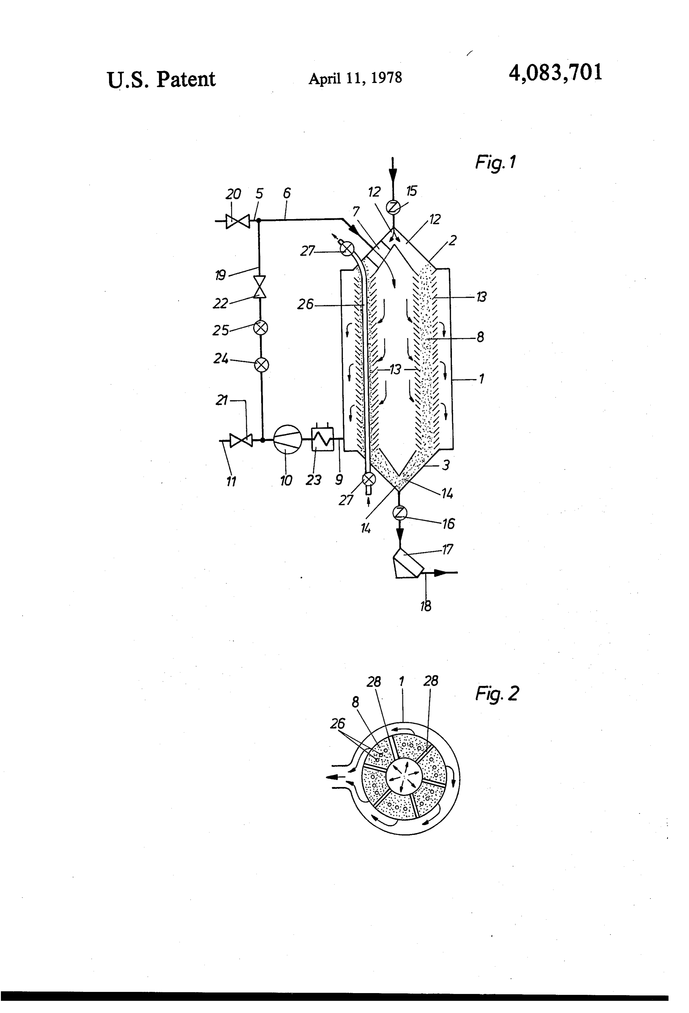
activated carbon used under unfavorable operating BRIEF DESCRIPTION OF THE DRAWING conditions, tends towards spontaneous combustion 25 FIG. 1 shows a schematic lengthwise section through which might lead to the destruction of the desulphuriza an adsorber tion installation. The greater the propensity of the acti invention; andof the apparatus, in accordance with
the vated carbon to react with respect to sulphur dioxide FIG. 2 is a cross-sectional view of the apparatus of adsorption, the greater is the hazard of spontaneous FIG. 1.
combustion. Therefore, for the safe operation of such 30 installations means must be found to prevent the sponta DESCRIPTION OF THE PREFERRED neous combustion of the activated carbon. It has been EMBODIMENTS found that spontaneous combustion of the activated carbon takes place only when there is no gas flow or phur The adsorber shown is used for the removal of sul only slight gas flow through the fill. In these cases, the 35 tion. dioxide from the smoke gases of a boiler installa heat of reaction arising from quiet oxidation cannot be It comprises a housing with a cylindrical outside carried off. . . . . . . . .. . . ' jacket 1, a roof2 and a bottom section 3. The flue gas to It is, therefore, an object of the present invention to be desulphurized, after having passed the dust separa provide a process where the spontaneous combustion of tor, is introduced at a temperature between 110' and the activated carbon during shutdown or low-load op 40 140 C via the gas line 5 and the intake line 6through an eration of the adsorber is prevented. opening 7 in roof 2 of the adsorber. It flows radially Another object of the present invention is to provide from the inside outward through an annular heap 8 of an arrangement which is simple in design and construc activated carbon, is collected on the outside jacket 1 tion, and may be easily maintained in service. and after desulphurization, leaves the adsorber through A further object of the present invention is to provide 45 the exit line 9 in the vicinity of the bottom section3. An an arrangement which may be economically operated induced draft blower 10 located in the exit line 9 trans and which has a substantially long service life. ports the desulphurized flue gas through the waste gas line 11 to a chimney (not shown).
SUMMARY OF THE INVENTION The activated carbon with a granulation of 8 mm is The objects of the present invention are achieved by 50 supplied through a pipe system 12 located in roof 2 of providing that during shutdown or low-load operation, the adsorber. The fill builds up between two concentric the flue gases which have already been cleaned and are perforated walls 13, The perforated walls 13 consist of still present in the adsorber or in associated components sheet metal strips arranged in the manner of venetian are fed back and are passed. . once more through the blinds (louvers) through which the flue gas flows. The activated carbon fill. . . 55 activated charcoal is continuously withdrawn by in The feedback of the cleaned flue gases and their recir clined chutes 14 in the bottom 3 of the adsorber. Hence culation through the activated carbon fill increases the the fill travels downward as a unit. The supply and gas permeation so that the fill is fully immersed. In this withdrawal of the activated carbon proceeds in a gas case, the flue gases cool the activated carbon bed. This tight manner through the cell wheel gates 15 and 16. prevents overheating of the activated carbon and low 60 The loaded activated carbon, after the dust has been ers the temperature of the activated carbon considera removed on the filter 17, is transported by a conveyor bly below the spontaneous combustion temperature of 18 to a regeneration installation (not shown). The acti. the activated carbon, so that the hazard of spontaneous vated carbon which has been regenerated there and has combustion is avoided. Even already existing smolder been cooled by athermal regeneration to approximately ing fires can be put out by lowering the temperature of 130', is again filled into the adsorber via the pipe system the activated carbon. 12. The activated carbon is circulated between adsorp As an improvement of the process, in accordance tion installation and regeneration installation to facili with the present invention, it is proposed that the fed tate continuous operation. ..
Page 4
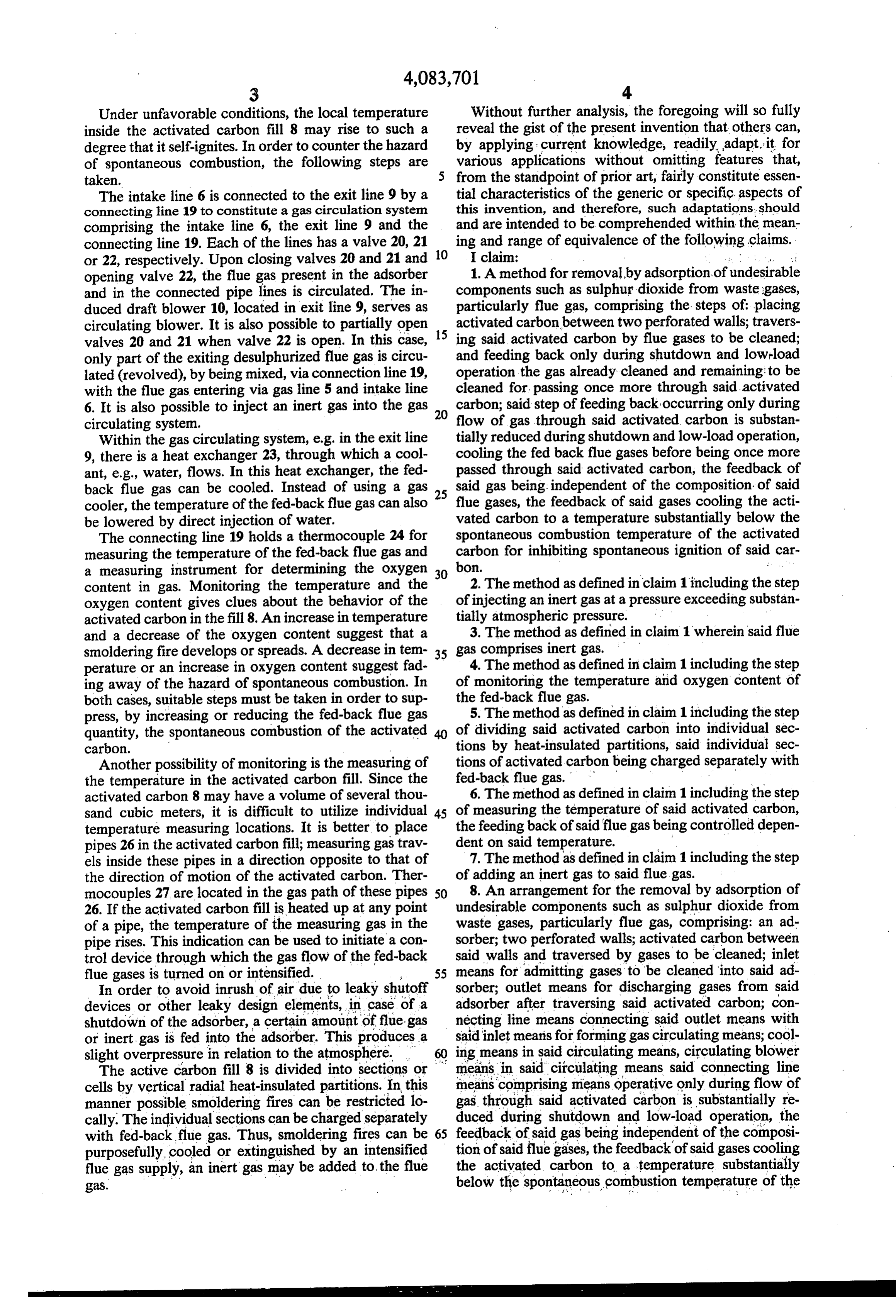
Under unfavorable conditions, the local temperature Without further analysis, the foregoing will so fully inside the activated carbon fill 8 may rise to such a reveal the gist of the present invention that others can, degree that itself-ignites. In order to counter the hazard by applying current knowledge, readily adapt. it for of spontaneous combustion, the following steps are various applications without omitting features that, taken. from the standpoint of prior art, fairly constitute essen The intake line 6 is connected to the exit line 9 by a tial characteristics of the generic or specific aspects of connecting line 19 to constitute a gas circulation system this invention, and therefore, such adaptations. should comprising the intake line 6, the exit line 9 and the and are intended to be comprehended within the mean connecting line 19. Each of the lines has a valve 20, 21 ing and range of equivalence of the following claims. or 22, respectively. Upon closing valves 20 and 21 and 10 I claim: . . . .. . . opening valve 22, the flue gas present in the adsorber 1. A method for removal by adsorption of undesirable and in the connected pipe lines is circulated. The in components such as sulphur dioxide from waste gases, duced draft blower 10, located in exit line 9, serves as particularly flue gas, comprising the steps of placing circulating blower. It is also possible to partially open 15 activated carbon between two perforated walls; travers valves 20 and 21 when valve 22 is open. In this case, ing said activated carbon by flue gases to be cleaned; only part of the exiting desulphurized flue gas is circu and feeding back only during shutdown and low-load lated (revolved), by being mixed, via connection line 19, operation the gas already cleaned and remaining to be with the flue gas entering via gas line 5 and intake line cleaned for, passing once more through said activated 6. It is also possible to inject an inert gas into the gas 20 carbon; said step of feeding back occurring only during circulating system. flow of gas through said activated carbon is substan Within the gas circulating system, e.g. in the exit line tially reduced during shutdown and low-load operation, 9, there is a heat exchanger 23, through which a cool cooling the fed back flue gases before being once more ant, e.g., water, flows. In this heat exchanger, the fed passed through said activated carbon, the feedback of back flue gas can be cooled. Instead of using a gas 25 said gas being independent of the composition of said cooler, the temperature of the fed-back flue gas can also flue gases, the feedback of said gases cooling the acti be lowered by direct injection of water. vated carbon to a temperature substantially below the The connecting line 19 holds a thermocouple 24 for spontaneous combustion temperature of the activated measuring the temperature of the fed-back flue gas and carbon for inhibiting spontaneous ignition of said car a measuring instrument for determining the oxygen 30 bon.
content in gas. Monitoring the temperature and the 2. The method as defined in claim 1 including the step oxygen content gives clues about the behavior of the of injecting an inert gas at a pressure exceeding substan activated carbon in the fill 8. An increase in temperature tially atmospheric pressure.
and a decrease of the oxygen content suggest that a 3. The method as defined in claim 1 wherein said flue smoldering fire develops or spreads. A decrease in tem 35 gas comprises inert gas.
perature or an increase in oxygen content suggest fad of4.monitoringThe method as defined in claim 1 including the step the temperature and oxygen content of ing away of the hazard of spontaneous combustion. In both cases, suitable steps must be taken in order to sup the fed-back flue gas.
press, by increasing or reducing the fed-back flue gas 5. The method as defined in claim 1 including the step quantity, the spontaneous combustion of the activated 40 of dividing said activated carbon into individual sec carbon. tions by heat-insulated partitions, said individual sec Another possibility of monitoring is the measuring of tions of activated carbon being charged separately with the temperature in the activated carbon fill. Since the fed-back flue gas. . . . activated carbon 8 may have a volume of several thou 6. The method as defined in claim 1 including the step sand cubic meters, it is difficult to utilize individual 45 of measuring the temperature of said activated carbon, temperature measuring locations. It is better to place the feeding back of said flue gas being controlled depen pipes 26 in the activated carbon fill; measuring gas trav dent on said temperature.
els inside these pipes in a direction opposite to that of 7. The method as defined in claim 1 including the step the direction of motion of the activated carbon. Ther of adding an inert gas to said flue gas. mocouples 27 are located in the gas path of these pipes 50 8. An arrangement for the removal by adsorption of 26. If the activated carbon fill is heated up at any point undesirable components such as sulphur dioxide from of a pipe, the temperature of the measuring gas in the waste gases, particularly flue gas, comprising: an ad pipe rises. This indication can be used to initiate a con sorber; two perforated walls; activated carbon between trol device through which the gas flow of the fed-back said walls and traversed by gases to be cleaned; inlet flue gases is turned on or intensified. M 55 means for admitting gases to be cleaned into said ad In order to avoid inrush of air due to leaky shutoff sorber; outlet means for discharging gases from said devices or other leaky design elements, in case of a adsorber after traversing said activated carbon; con shutdown of the adsorber, a certain amount of flue-gas necting line means connecting said outlet means with or inert gas is fed into the adsorber. This produces a said inlet means for forming gas circulating means; cool slight overpressure in relation to the atmosphere. ing means in said circulating means, circulating blower The active carbon fill 8 is divided into sections or means in said circulating means said connecting line cells by vertical radial heat-insulated partitions. In this means comprising means operative only during flow of manner possible smoldering fires can be restricted lo gas through said activated carbon is substantially re cally. The individual sections can be charged separately duced during shutdown and low-load operation, the with fed-backflue gas. Thus, smoldering fires can be 65 feedback of said gas being independent of the composi purposefully, cooled or extinguished by an intensified tion of said flue gases, the feedback of said gases cooling flue gas supply, an inert gas may be added to the flue the activated carbon to a temperature substantially gas. below the spontaneous combustion temperature of the
Page 5
activated carbon for inhibiting spontaneous ignition of 13. The arrangement as defined in claim 12 wherein said carbon. each of said sections is separately connected to said gas 9. The arrangement as defined in claim 8 wherein the circulating means.
interior of said adsorber is maintained at a pressure 14. The arrangement as defined in claim 12 wherein exceeding substantially atmospheric by said flue gas. said partitions are heat-insulated. 10. The arrangement as defined in claim 8 including 15. The arrangement as defined in claim 8 including measuring means in said gas circulating means for mea pipe means in said activated carbon for conducting gas suring the oxygen content in the flue gas passed through to be measured; and thermocouple means in said pipe said connecting line means. means for measuring the temperature of gases through 11. The arrangement as defined in claim 8 including 10 said pipe means.
temperature measuring means in said gas circulating control 16. The arrangement as defined in claim 15 including means for measuring the temperature of the flue gas for operating means connected to said thermocouple means passed through said connecting line means, said con gases in contactsaidwith circulating blower means upon the said thermalcouple means attain necting line means comprising feedback means. 15 ing a predetermined temperature. 12. The arrangement as defined in claim 8 including partitions between said perforated walls for dividing the said17.circulating
The arrangement as defined in claim 8 wherein blower means is in said outlet means and space between said perforated walls into individual comprises an induced draft blower.
sections.
Provenance
- Collection
- Cited prior art
- Original PDF
- patentimages.storage.googleapis.com →
- Filed
- 1976-06-14
- Pages
- 5
- Method
- pdftotext (the PDF's own text layer) + pdftoppm 300dpi page scans
- Source
- Google Patents bibliographic record
- Granted
- 1978-04-11
- Inventors
- Rolf Noack; Deutsche Babcock AG
- Transcribed from
- patentimages.storage.googleapis.com →