patent · US3180079
Apparatus for operating spark-ignition internal combustion engines
27 April 1965
Page 1
Drawing sheet — no readable text.
Page 2
United States Patent Office Patented Apr. 27, 1965
crankshaft of engine 6, is preferably adapted so that 3,188,079 it may be used either as an air-motor or as a supercharger, APPARATUS FOR of ERAfNG SPARK-IGNATION depending upon the speed ratio provided between the INTERNAL COM BUSTON ENGINES shafts 13 and S4. Thus positive-displacement devices John H. Freeman, Jr., Crystal Lake, Ill., assiglior to The
Pure Oil Company, Chicago, Ill., a corporation of Ohio Such as the Roots, vane, Lysholm, or Bicera types may be used.
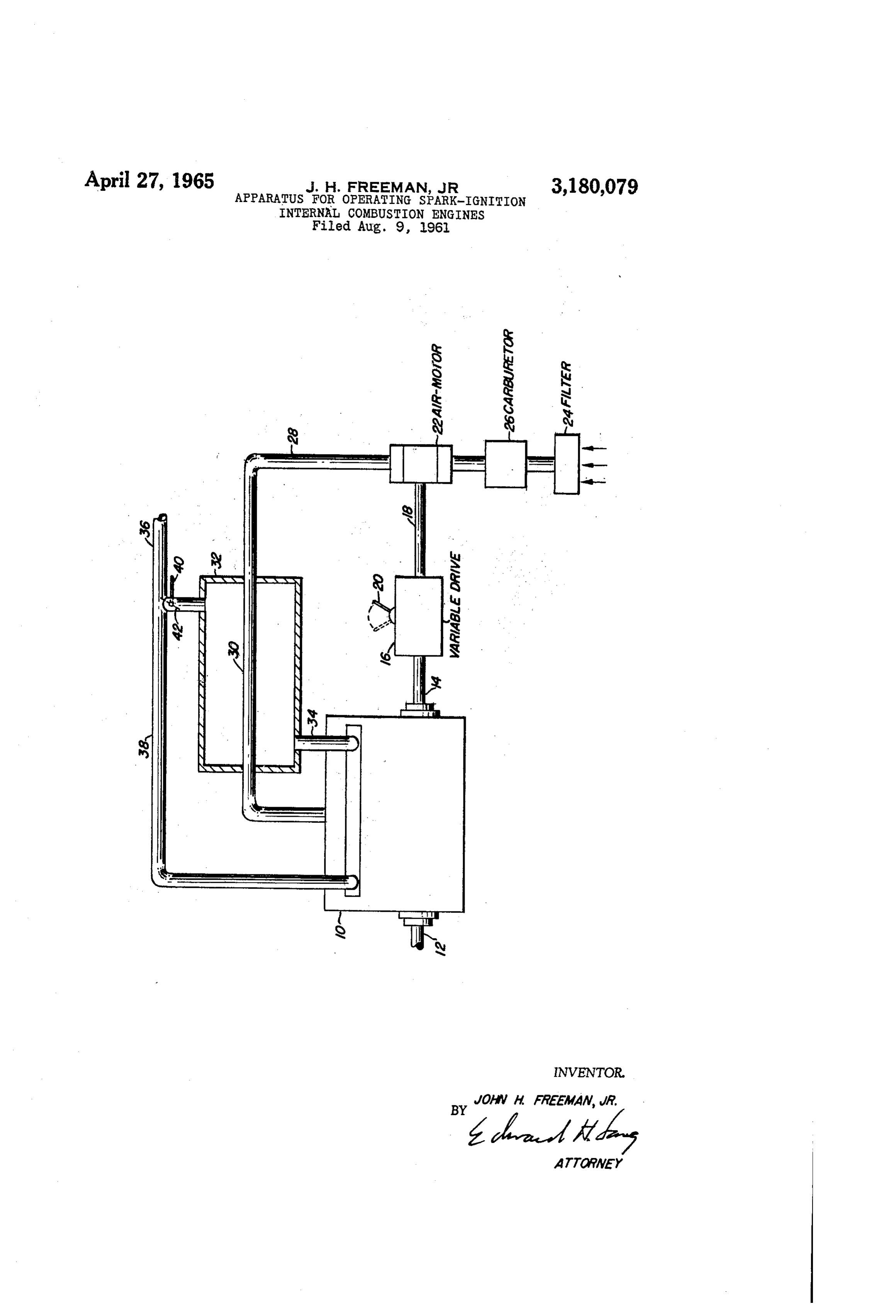
Filed Aug. 9, 1961, Ser. No. 30,467 Air entering the system through air cleaner 24 flows 1 Claim. (C. 60-14) then to carburetor 26, wherein a suitable proportion of This invention relates to a novel method and appa fuel is mixed with the air. The air-fuel mixture then flows ratus for controlling the output of spark-ignition internal 0 to air-motor 22, then through line 28 to tube 30 of heat combustion engines whereby the part-load fuel economy eXchanger 32, and thence to the engine intake-manifold. of the engine is significantly increased. In a specific Some of the exhaust from the engine passes through line aspect, the invention relates to a method and apparatus 34 to the shell of heat exchanger 32, and thence to the whereby the maximum power output of the engine under main exhaust line 35. Another portion of the exhaust conditions of high-load may also be increased. 5 flows through bypass line 38 to inain exhaust line 36. The Almost all spark-ignition internal-combustion engines proportion of engine exhaust flowing through the heat are rendered flexible in operation by means of throttling exchanger 32 may be varied by movement of arm 40 the incoming air, or air-fuel mixture, to the engine. This which connects to butterfly valve 42. throttling is accomplished by passing the charge of air It will be evident that the ratios of the speeds of the and fuel through a valve (throttle plate) so that the 20 engine crankshaft and of air-motor 22 is determined by mixture is expanded without doing mechanical work upon variable-speed drive :6. It is further evident that, in the or obtaining useful work from the flowing mixture. Thus, absence of throttling, the air-flow rate through the engine the condition of the mixture in the intake manifold, after is proportional to engine speed, and the air-flow rate throttling, is such that the pressure and density of the through the air-motor is proportional to the speed of the mixture is greatly reduced, while the temperature remains 25 air motor. Accordingly, the ratio of speeds of the engine substantially unchanged. crankshaft and of the air motor may be adjusted to pro It is an object of this invention to provide an improved duce any desired engine manifold pressure. When the method for the operation of spark-ignition internal ratio of engine speed to air-motor speed is low, the mani combustion engines whereby improved economies may be fold pressure will be high. As the ratio of engine speed obtained under low-load operating conditions. 30 to air-motor speed increases, the manifold pressure will Another object of this invention is to provide a novel drop. It is evident that there will be one ratio of engine apparatus for controlling the power output of internal speed to air-motor speed, depending upon the displace combustion engines, whereby increased engine efficiency ment of the engine and the capacity of the air-motor, at may be obtained. which the manifold pressure will be approximately Yet another object of this invention is to provide an atmospheric pressure. At this ratio, the air-motor will assembly for controlling the power output of a spark idle, that is, the air-motor will have no work done upon ignition internal-combustion engine whereby the maximum it by the air, and thus will transmit no torque to the power output of the engine is increased. engine crankshaft. Neither will the air-motor do any These and other objects of the invention will become work upon the air, nor receive any torque from the apparent from the following detailed description. 40 engine crankshaft. Air flow through the air-motor will Briefly, in accordance with the method of this inven be substantially at constant pressure and without expan tion, the power output of an internal-combustion engine ision. Operation of the engine under such conditions is controlled by flowing the intake air through an air is equivalent to wide-open throttle operation of a con motor such that the air is expanded under substantially ventionally carbureted internal-combustion engine. As adiabatic conditions, whereby useful mechanical energy the ratio of engine speed to air-motor speed is increased, is derived from the expanding air. This energy is fed the air volume handled by the engine exceeds the intake to the crankshaft of the engine. The engine manifold air volume, to the air-motor, and consequently expansion pressure, and power output, is regulated by adjusting the occurs in the air-motor and a pressure drop is developed Speed ratio between the air motor and the crankshaft. across the air-motor. Since the expansion in an air The drawing illustrates the basic layout of one embodi 50 motor is stibstantially adiabatic, the temperature of the ment of the invention in diagrammatic form. air, as well as the pressure, will decrease substantially, The invention is best described with reference to the and mechanical energy produced by the air-motor will drawing, wherein the numeral 10 designates a conven be transmitted through the variable-speed drive to the tional six-cylinder, spark-ignition, internal-combustion engine crankshaft. it will be evident that where the ratio engine having a power output shaft 2 and a secondary 55 provided by variable-speed drive 16 is altered to decrease output shaft 14 which is connected to a variable-speed the ratio of engine speed to air-motor speed below that drive 6. The ratio between the shafts 14 and 18, that at which the air-motor idles, the air-motor, if of a type is, the ratio of input to output speeds of the variable capable of acting as a compressor, will serve as a super drive 6 is controlled by the position of engine-control charger for the engine and increase the engine manifold rod 28. In the control of engine output power, the posi pressure above atmospheric pressure. A Roots blower is tioning of rod 26 operates in a manner analogous to the 60 an example of a device capable of use either as a com positioning of the throttle lever in conventional engine pressor or as an air-motor, depending upon the speed of operation, as will hereinafter become apparent. Any of operation and the air-flow rate. Thus, depending upon the positioning of control arm 20, engine 0 will be the numerous belt-drive or cone drive variable speed throttled devices, which are well known in the art, may be em 65 During orpart-load supercharged.
operation, spark-ignition internal ployed in the apparatus of this invention. However, it is preferred that a variable-speed drive, such as disclosed combustion engines customarily operate at pressure ratios by Oehrli, in U.S. Patent No. 2,835,238, be employed. of about 2.5 or less, that is, at manifold vacuums not in The ratio of engine-shaft speed to the output-drive-shaft excess of about 18 inches of mercury. At intermediate 18 speed will be substantially higher, however, than when 70 loads, the manifold vacuum will decrease from 18 inches such device is employed for supercharging an engine. of mercury as the manifold pressure approaches atmos Air-motor 22, which drives shaft 13 and thus the pheric pressure. The low-load condition of about 18
Page 3
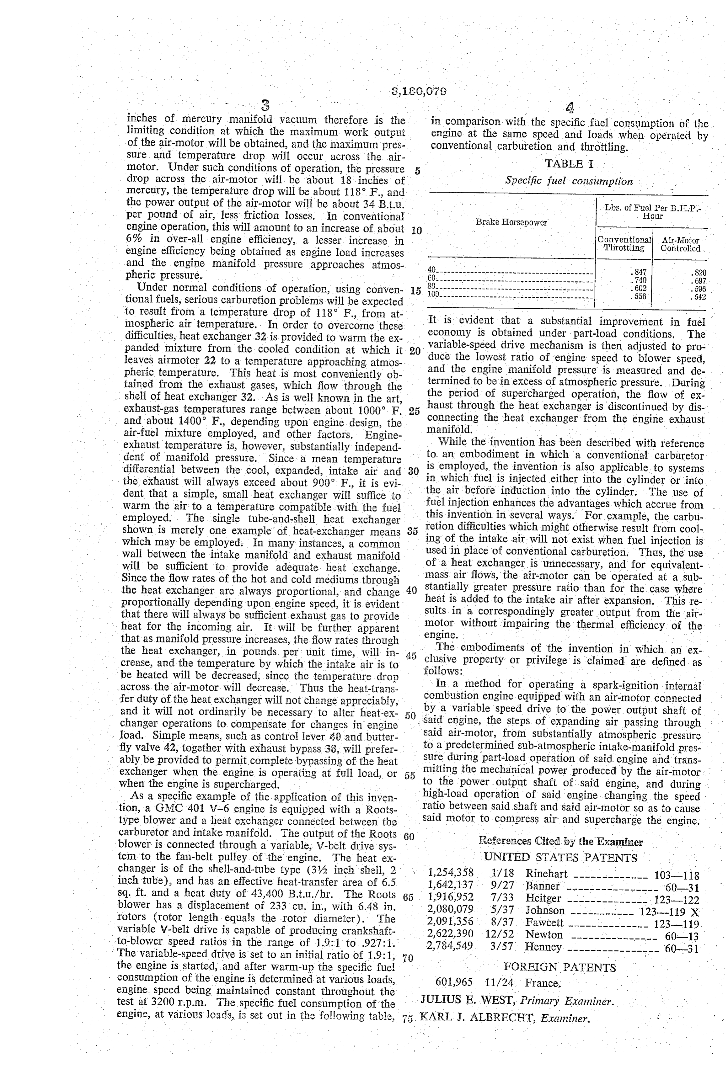
inches of mercury manifold vacuum therefore is the in comparison with the specific fuel consumption of the limiting condition at which the maximum work output engine at the same speed and loads when operated by of the air-motor will be obtained, and the maximum pres conventional carburetion and throttling. sure and temperature drop will occur across the air TABLE motor. Under such conditions of operation, the pressure 5 drop across the air-motor will be about 18-inches of Specific fuel consumption mercury, the temperature drop will be about 118 F., and the power output of the air-motor will be about 34 B.t.u. Lbs. of Fuel Per B.H.P. per pound of air, less friction losses. In conventional Brake Horsepower our engine operation, this will amount to an increase of about O 6% in over-all engine efficiency, a lesser increase in Conventional Air-Motor Throttling Controlled engine efficiency being obtained as engine load increases and the engine manifold pressure approaches atmos pheric pressure. . . 847
Under normal conditions of operation, using conven . . 602 . 596 tional fuels, serious carburetion problems will be expected .556 . 542 to result from a temperature drop of 118 F., from at mospheric air temperature. In order to overcome these It is evident that a substantial improvement in fuel difficulties, heat exchanger 32 is provided to warm the ex economy is obtained under part-load conditions. The panded mixture from the cooled condition at which it 20 variable-speed drive mechanism is then adjusted to pro leaves airmotor 22 to a temperature approaching atmos duce the lowest ratio of engine speed to blower speed, pheric temperature. This heat is most conveniently ob and the engine manifold pressure is measured and de tained from the exhaust gases, which fiow through the termined to be in excess of atmospheric pressure. During shell of heat exchanger 32. As is well known in the art, the period of supercharged operation, the flow of ex haust through the heat exchanger is discontinued by dis exhaust-gas temperatures range between about 1000 F. 25 connecting the heat exchanger from the engine exhaust and about 1400 F., depending upon engine design, the air-fuel mixture employed, and other factors. Engine manifold.
exhaust temperature is, however, substantially independ While the invention has been described with reference dent of manifold pressure. Since a mean temperature to an embodiment in which a conventional carburetor differential between the cool, expanded, intake air and 30 is employed, the invention is also applicable to systems the exhaust will always exceed about 900. F., it is evi in which fuel is injected either into the cylinder or into dent that a simple, small heat exchanger will suffice to the air before induction into the cylinder. The use of warm the air to a temperature compatible with the fuel fuel injection enhances the advantages which accrue from employed. The single tube-and-shell heat exchanger this invention in several ways. For example, the carbu shown is merely one example of heat-exchanger means 35 retion difficulties which might otherwise result from cool which may be employed. En many instances, a common ing of the intake air will not exist when fuel injection is wall between the intake manifold and exhaust manifold used in place of conventional carburetion. Thus, the use of a heat exchanger is unnecessary, and for equivalent will be sufficient to provide adequate heat exchange.
Since the flow rates of the hot and cold mediums through mass air flows, the air-motor can be operated at a sub the heat exchanger are always proportional, and change 40 stantially greater pressure ratio than for the case where proportionally depending upon engine speed, it is evident heat is added to the intake air after expansion. This re that there will always be sufficient exhaust gas to provide sults in a correspondingly greater output from the air heat for the incoming air. It will be further apparent motor without impairing the thermal efficiency of the that as manifold pressure increases, the flow rates through engine. -
the heat exchanger, in pounds per unit time, will in 45 The embodiments of the invention in which an ex crease, and the temperature by which the intake air is to clusive property or privilege is claimed are s defined as be heated will be decreased, since the temperature drop follows: In a method for operating a spark-ignition internal across the air-motor will decrease. Thus the heat-trans combustion engine equipped with an air-motor connected fer duty of the heat exchanger will not change appreciably, by a variable speed drive to the power output shaft of and it will not ordinarily be necessary to alter heat-ex changer operations to compensate for changes in engine said engine, the steps of expanding air passing through load. Simple means, such as control lever 49 and butter said air-motor, from substantially atmospheric pressure fly valve 42, together with exhaust bypass 38, will prefer to a predetermined Sub-atmospheric intake-manifold pres ably be provided to permit complete bypassing of the heat sure during part-load operation of said engine and trans exchanger when the engine is operating at full load, or 55 mitting the mechanical power produced by the air-motor when the engine is supercharged. to the power output shaft of said engine, and during As a specific example of the application of this inven high-load operation of said engine changing the speed tion, a GMC 401 V-6 engine is equipped with a Roots ratio between said shaft and said air-motor so as to cause type blower and a heat exchanger connected between the said motor to compress air and supercharge the engine. carburetor and intake manifold. The output of the Roots 60 blower is connected through a variable, V-belt drive Sys References Cited by the Examiner tem to the fan-belt pulley of the engine. The heat ex UNITED STAES PATENTS changer is of the shell-and-tube type (3% inch shell, 2 1,254,358, 1/18 Rinehart ------------- 103-118 inch tube), and has an effective heat-transfer area of 6.5 1,642,137 9/27 Banner ----------------' 60-31 sq. ft. and a heat duty of 43,400 B.t.u./hr. The Roots 1,916,952 7/33 Heitger ------------- 123-122 blower has a displacement of 233 cu. in., with 6.48 in. 2,080,079 5/37 Johnson ----------- 123-119 X rotors (rotor length equals the rotor diameter). The 2,091,356, 8/37 Fawcett -------------- 123-119 variable V-belt drive is capable of producing crankshaft 2,622,390 12/52 Newton --------------- 60-13 to-blower speed ratios in the range of 1.9:1 to .927:1. 2,784,549 3/57 Henney ---------------- 60-31 The variable-speed drive is set to an initial ratio of 1.9:1, 70 the engine is started, and after warm-up the specific fuel FOREIGN PATENTS consumption of the engine is determined at various loads, 601,965 11/24. France. engine speed being maintained constant throughout the test at 3200 rp.m. The specific fuel consumption of the JULIUS E. WEST, Primary Examiner. engine, at various loads, is set out in the following table, 5 KARL J. ALBRECHT, Examiner.
Provenance
- Collection
- Cited prior art
- Original PDF
- patentimages.storage.googleapis.com →
- Filed
- 1961-08-09
- Pages
- 3
- Method
- pdftotext (the PDF's own text layer) + pdftoppm 300dpi page scans
- Source
- Google Patents bibliographic record
- Granted
- 1965-04-27
- Inventors
- Jr John H Freeman; Pure Oil Co
- Transcribed from
- patentimages.storage.googleapis.com →