patent · US2081243
Apparatus for pasteurizing liquids
25 May 1937
Page 1
Drawing sheet — no readable text.
Page 2
Drawing sheet — no readable text.
Page 3
Patented May 25, 1937
PATENT office
APPARATUs FoR PASTEURIZING LIQUIDs -.' Barnett W. Macy, Jacksonville, Fla.
Application September 8, 1933, serial No. 688,683
This invention relates to the pasteurization of not so very much better than it was originally. liquids, and its objects are as follows:- This fact has been recognized but not remedied First, to subject the liquid to an alternating to any degree of satisfaction. If the milk is electrical current which is interrupted at such carried to a too high temperature in order to: 5 a rate which it has been determined is destruc insure killing the bacteria the milk takes on a 5 tive of a great percentage of bacterial life. scorched taste with a destruction of the cream Second, to produce the foregoing interruptions line. In order to play safe, milk treating estab by a magnetic or other switch, said interruptions lishments will stay On the side of lower tem literally exploding the bacteria without having peratures. This avoids the last two effects, but: 10, any detrimental effect on the liquid. . . . . . . the bacterial count per cubic centimeter is far 10 . Third, to pasteurize liquids according to the higher than it should be as already pointed out, herein disclosed process which does not depend The instant process is based on projecting on heat for the destruction of the bacteria. rapid surges, or impulses of alternating electrical Fourth, to provide a pasteurizing apparatus current across the milk course so as to electro including an electrolytic unit in which the cen cute the bacteria solely by the interruptions of 15 tral and outer electrodes are so mounted with the current and not by such heat as it may cause. respect to the inlet dome that the liquid is not
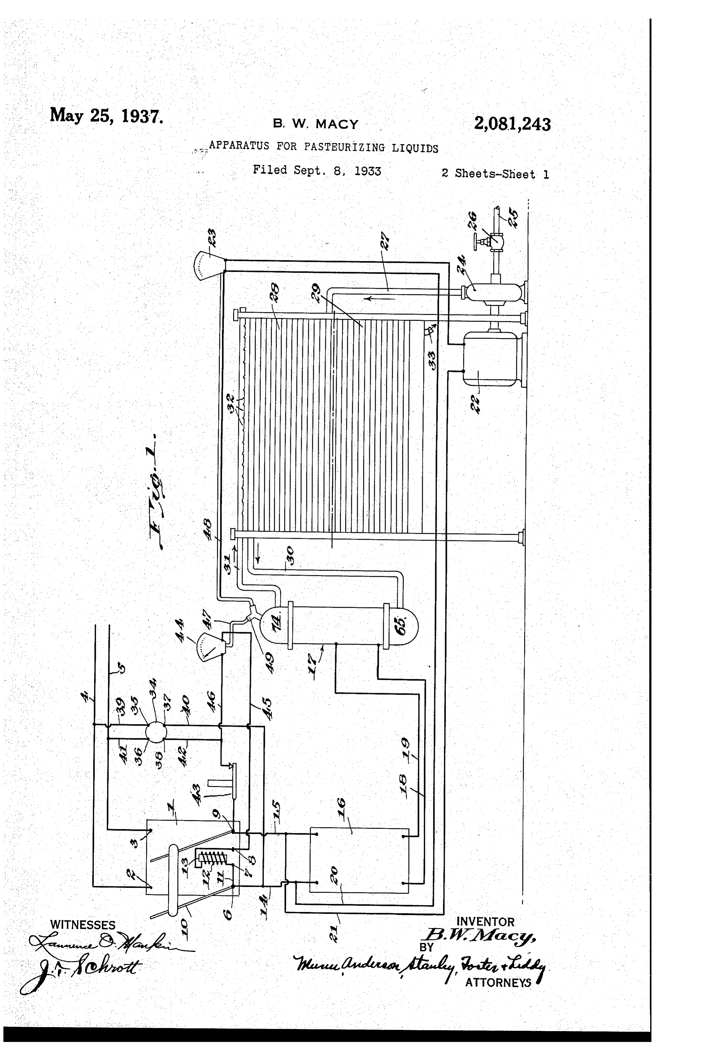
Attention is directed to Figure 1. A main Switch subjected to the electrical pulsations until well has contacts 2, 3 to which the main line wires 4, 5 are connected. The switch also includes on its course through the unit. . . . . . . . . .
20 Fifth, to supplement the pasteurizing appa four-terminals 6, 7, 8, 9. . . . .. 20 ratus with an electrical interrupter the sole The terminals. 6, 9 are the pivots of a double bladed switch member. O. The terminals. 6,7 function of which is to deliver the current to the are connected by a bus f. The terminals 7, 8 electrical unit in relatively slow and intenseim pulses or jolts, the periodic rate of the impulses have the opposite ends of the winding 2 of a 25 being variable by adjustment of the interrupter.
solenoid connected to them, the movable core: 3
Other objects and advantages will appear in of which has any suitable connection (not 25 the following specification, reference being had shown) with the switch member 10 so that a drawing in of the core upon energization of the to the accompanying drawings in which, i.
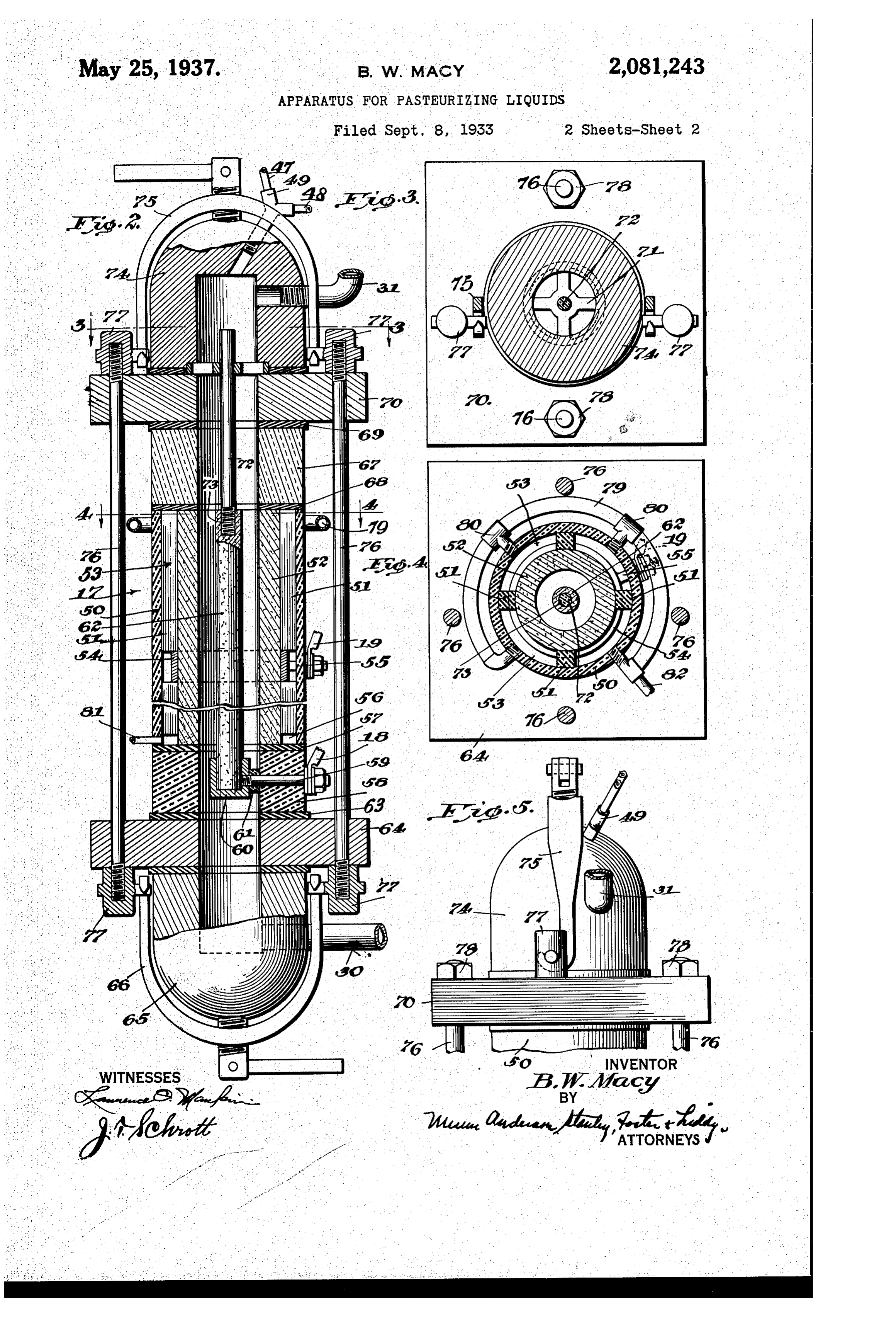
Figure 1 is a diagram illustrating the means solenoid will move the switch member into en by which the process is carried out. . . . . . gagement, with the contacts 2, 3, in a circuit 30 Figure 2 is a central vertical section of the closing position.
electrolytic unit which is one of the important Wires 4, 5, connect the terminals 6, 9 with an interrupter 6. The details of this are pur features of the apparatus, parts being shown in elevation. posely omitted because any one of a variety of as 3-3Figure 3 is across section taken. . . on of Figure 2.
the line types
of interrupters can be employed. It com prises a current-interrupting switch, magnetic 35
Figure 4 is a cross section taken on the line or otherwise, which interrupts the current at the 4-4 of Figure 2. . .. . . . .. . rate of 200 or more times perminute. The inter Figure 5 is a detail side elevation of the out rupter is connected with an electrolytic pasteur let dome, the view being taken at 90° from the izing unit 7 by means of wires 18, 9. position in Figure 2.
some of the most recent developments in the 4,Wires 20, 2, are connected across the wires 5 at one end. The wire 2 has a motor 22 reatment of milk since the germ theory came to connected in series with it. Thereafter both be generally known, are based on the action of wires lead to a compensating resistance diagram 5 an electrical current the primary purpose of matically indicated 23. The motor drives a pump 45 which is to heat the milk to a temperature of 24 which draws the milk from a source of supply - approximately 150 F. and then cool it to a suit through a pipe, 25 which has a valve 26 in it. able storage temperature. It has been discov The pump has an outlet pipe 27 which delivers ered by actual experimentation that unless the the milk to the bottom end of a regenerative temperature is raised to a sufficiently high point cooler 28. ; ". . ...; 50 the heating of the milk simply has the effect of The regenerative cooler and also the refriger suspending the animation of an undesirably high ating cooler 29 beneath it are of known types, percentage of the bacteria, and that when this the former having a discharge pipe 30 which bacteria goes onto a cooler place it comes to life, leads to the unit 7. After the milk goes through so to speak, with the treated milk in a condition said unit it leaves at an outlet pipe 3 f. That is
Page 4
part of this pipe situated over the cooler 28 is perforated at 32. As the milk flows over the coils the thermometer 44 will break the holding circuit through the Solenoid f2 and cause the latter to of the cooler 28 there is an exchange of heat, and move the switch member 0 to the circuit-open When the milk reaches the cooler 29 it is reduced ing position. Should the thermometer fail, the to a, storage temperature before flowing to the same effect is obtainable manually by pressing bottling machine by way of the outlet 33. the safety Switch 43. It is undesirable to thus A starter button 34 is connected in parallel interrupt the continuous operation of the proc across the line wires 4, 5. This button is a dou eSS. Such an interruption is normally prevented ble pole switch which includes contacts 35, 36, by the companisating resistance 23. O 37, and 38. A wire 39 connects the main line When the temperature of the milk reaches 10 wire 4 to the contact 35. A wire 40 connects the a high point, but not high enough to cause the contact 37 with the wire 4. A wire connects automatic operation of the thermometer 44, the contact 36 with the main line wire 5. A wire resistance 23 will be auton Latically operated to 42 connects contact 38 with the main Switch ter speed up the motor 22 and so cool the milk by 5 minal 9, this wire having a normally closed Safety pumping more through. Should the temperature Switch 43 in it. drop toward an undesirable low point the com The switch 43 is adapted for manual opera pensating resistance 23 will slow up the motor tion, and its purpose is to de-energize the sole 22 and so slow the flow through the unit 7, en noid 2 for the throwing of the switch member abling the milk to reach a satisfactory working 20 O to an open position. The same result, is ob temperature.
tained automatically by a thermometer 44. This It has been stated that the current used in is an electrical thermometer of a known type. the electrolytic unit must be alternating electri It is connected across the terminals 8, 9 by a cal current. This is necessary because it has wire 45 and a wire 46 which is connected onto been discovered that the use of direct current 25 the wire, 42 and so controls a holding circuit.
will separate the butter fat from the milk. Ob 25
The temperature of the milk in the upper end viously this is undesirable. In subjecting the of the unit is transmitted to the thermometer milk to the electrical impulses, the rate per min 44 through a suitable form of manometer tube ute will be regulated to be in proportion to the 4. The compensating resistance 23 is operated rate of flow of the milk through the electrolytic 30 by milk pressure in the upper end of the unit unit.
also through a suitable type of manometer 30 tube 48. These tubes are attached to a fitting
If the rate of flow is increased the number of 49 which, in practice, will be internally equipped interruptions per minute will be increased. Con for temperature-pressure responses. versely, if the rate of flow is diminished the num 35 The operation of the process is as follows: Con ber of interruptions per minute will be decreased. sider the main switch as being open as shown. To this end the interrupter 6 is made adjustable 35 Press the starter button 34, A current flow from in practice. The effect of the foregoing adjust an alternating source of current is traced Over ment is to maintain a Substantially uniform num ber of electrical impulses perminute per unit vol the wire 4, wire 39, contacts 35, 37, wire 40 to lume of milk.
40 terminal 6, bus f, terminal 7, winding 2, termi
This principle applies to the pasteurization of 40 nal 8, wire 45, through thermometer 44, wires milk. The majority of bacteria will be killed, but 46 and 42, contacts 38, 36, wire 4 to main wire not all. The interrupter 6 is adapted to be 5 and again to said Source of current. speeded up to cause a sterilization of the milk. The energization of the solenoid operates the This simply means interrupting the alternating 45 core 3 and its connections to the Switch mem electrical current at such a high rate per minute 45 ber O to throw the latter against the contacts and consequently subjecting the milk to so many 2, 3 in the circuit-closing position. Current then impulses per minute that the bacterial life will be flows as follows, the starter button 34 having eliminated entirely. This will produce absolutely been released in the meantime: from the current sterile liquid, whether it be milk, as in the ex 50 source over wire 4, contact 2, terminal 6, wire ample given, or other liquid. 4 through one side of the interrupter f6, wire Attention is next directed to the details of the 8 to the unit 7, wire 9, to the other side of the interrupter 6, wire 5, terminal 9, contact unit 7 (Fig. 2). This comprises a non-metallic cylinder or water jacket 50 preferably of mate 3 and over wire 5 back to the source of current.
55 Current is supplied the motor 22 at the same rial commonly known as bakelite. It may con time by way of wires 20, 2 and the compensat sist spacingof any other insulating material. Inside of it 55 ing resistance 23. . Milk is being pumped through aremetallic means 5 (Fig. 4) which space ancin cylinder 52 of electrical conductive mate the regenerative cooler 28. Milk has been given rial from the cylinder 50 So as to produce chan merely as an instance of one liquid which is 60 adapted to be treated. The process is intended nels 53 (Fig. 4) for the passage of water. to handle liquids other than milk. The milk to Athe copper or other Conducting band 54 is secured 60 outside of the cylinder 52 by shrinking or flows through the unit 7, and as it flows through Otherwise. This has a terminal 55 to which the it is subjected to an electrical current which is wire interrupted by the interrupter 6 at a frequency 5, in 9the (Fig. 1) is connected. The spacing means form of cross sectionally non-circular 65 of 200 or more interruptions per minute. This is a relatively slow rate of interruption, and its rods of insulating material are separated at the 65 band 54. This is merely for simplification in effect is to subject the bacteria to intense im construction. The Wei ends of the rod are pulses or jolts which are all the more severe spaced from the bottom of the cylinders 50, 52 because of their being slow. It has been found to provide a bottom space 56.
0. that milk having a bacterial count of 370,000 The cylinders 50, 52 rest. On a gasket 57. This 70 per cubic centimeter at the input of the unit 7 rests on a collar 58 of insulating material. This has been pasteurized to approximately 2,000 per collar carries a terminal 59 to the outer end of cubic centimeter at the Output.
Should the temperature of the milk at the out which the wire 8 (Fig. 1) is connected. The in s put side of the unit 7 become undesirably high, ner end of it has a cup 60 attached to it. A spacer centers the cup in the bore of the collar 58. Is
Page 5
The interrupted current flows to the central ... The cup contains the lower end of a non-metallic electrode but electrical conductive rod 62. The rod 62 and understood. 62 whence it is conducted off as already The central electrode is longer than cylinder 52 are herein known as the central and the Outer electrode, outer electrodes. . . . . . It extends well into the col 5. The collar 58 rests on a gasket 63. This rests cup lar 58 which contains the cup 60 to hold it. The on a head 64. This head has an inlet dome 65 posely 60 is a conductor of electricity, but it is pur beneath it. It is to this dome that the discharge situated outside of the outer electrode 52 pipe 30 (Fig. 1) is connected. This dome is held So that there may be no interference whatso nplace by clamping means 66. ever with the killing action of the current, nor Near the upper end of the unit there is a collar any obstruction nor diminution of the immedi O 67. This is preferably of glass so that the milk ate passageway through which the liquid flows can be inspected as it flows through the unit. It during its electrolytic treatment. is situated between gaskets 68, 69, the first rest It is to be observed that this passageway is ling on top of the cylinder 50, 52, the latter con part of B. bore of uniform diameter beginning 15 tacting ahead 70 in confronting relationship to inthethe bottom inlet dome, continuing through lower head 64, collar 58 and ending in the theThe head 64.
bore of this head is crossed by a spider 7 f. outlet dome 4, after being traced through the The spider provides a guide for an insulating rod top collar and upper head 70. This bore pro 72 which is screwed into the upper end of the vides for the uniform flow of the liquid. There 20 central electrode 62 as at 73. The spider holds are no offsets in it to act as obstructions, the rod 72 loosely. The rod extends above the I claim:- spider into the dome, and when the dome is de 1. A cylinder of conductive material consti tached the extended end of the rod can be taken tuting an Outer electrode, the bore of said cyline hold of to lift the central electrode 62 enough to der providing a liquid passageway, a rod of con 25 enable swabbing out the interior of the outer ductive material axially positioned in the bore electrode. An outlet dome 74, similar to the constituting a central electrode and having one dome 65 is mounted on the head 70, being secured end extending beyond the end of the cylinder, by clamping means 75. The dome 74 has the means for making electrical current connections ! outlet pipe 3 connected to it (Fig.1). It also to the cylinder and rod, said means comprising a 30 30 hasSpanner the fitting 49 screwed into place as shown.
bolts 6 connect the confronting heads band attached to the cylinder and a cup for the reception of the extended end of the rod.
64, 70. When these are tightened, the heads are 2. An outer cylindrical electrode the bore of drawn toward each other tightly, compressing the which provides a liquid passageway, a spider ... various gaskets and making liquid tight connec 3 tions at the joints. The tightening means of the situated beyond bolts include lugs 77 which form part of the situated one end of said electrode, a cup 35 beyond the other end of the electrode, clamping means, and nuts 8 (Fig. 3). a central electrode axially positioned in the outer Water for cooling purposes is supplied the chan electrode to seat in the cup, and an insulating . . nel 53 (Fig. 4) by a tubing (preferably rubber) rod connected to the other end of the central 79, the points of introduction comprising a num electrode and passing through the Spider. 3. An electrolytic unit comprising an outer cy
iber of fittings 80. The fittings are directed into ... each of the channels, the channels being defined . indrical electrode and a central electrode in the by the spacing means 5 as already brought bore thereof, insulating collars and heads at the out. Water is conducted off from the bottom respective ends of the outer electrode, means to space 56(Fig. 2) by a discharge pipe 8. One of draw the heads together and so make tight joints 45 the fittings of the tubing 79 has an inlet pipe between the heads, collars and outer electrode, 82 connected to it. said means including lugs and Said heads and . . The operation of the unit 7 is readily under collars having bores in continuation of the bore ... stood. The entire electrode 52 is charged with of the outer electrode, inlet and outlet domes 50 electrical current. It is insulated from every having continuing bores, and clamping means 50 ...thing else excepting the current of liquid by the also holding onto the lugs and pressing on the domes collars 58 and 67 at the bottom and top. An en for detachably connecting the domes to the heads. tire volume of milk of a length equal to the:
length of the outer electrode 52 is charged at BARNET. W. MACY. 55 one time. 55
Provenance
- Collection
- Cited prior art
- Original PDF
- patentimages.storage.googleapis.com →
- Filed
- 1933-09-08
- Pages
- 5
- Method
- pdftotext (the PDF's own text layer) + pdftoppm 300dpi page scans
- Source
- Google Patents bibliographic record
- Granted
- 1937-05-25
- Inventors
- Barnett W Macy
- Transcribed from
- patentimages.storage.googleapis.com →