patent · US2318195
Ignition system
4 May 1943
Page 1
Drawing sheet — no readable text.
Page 2
Patented May 4, 1943
IGNITION systEM
Paul E. Cate, Knoxville, Tenn., assignor to The
Fulton Sylphon corporation Company, Knoxville, Tenn., a of Delaware
Application November 1, 1939, Seria No. 302,409
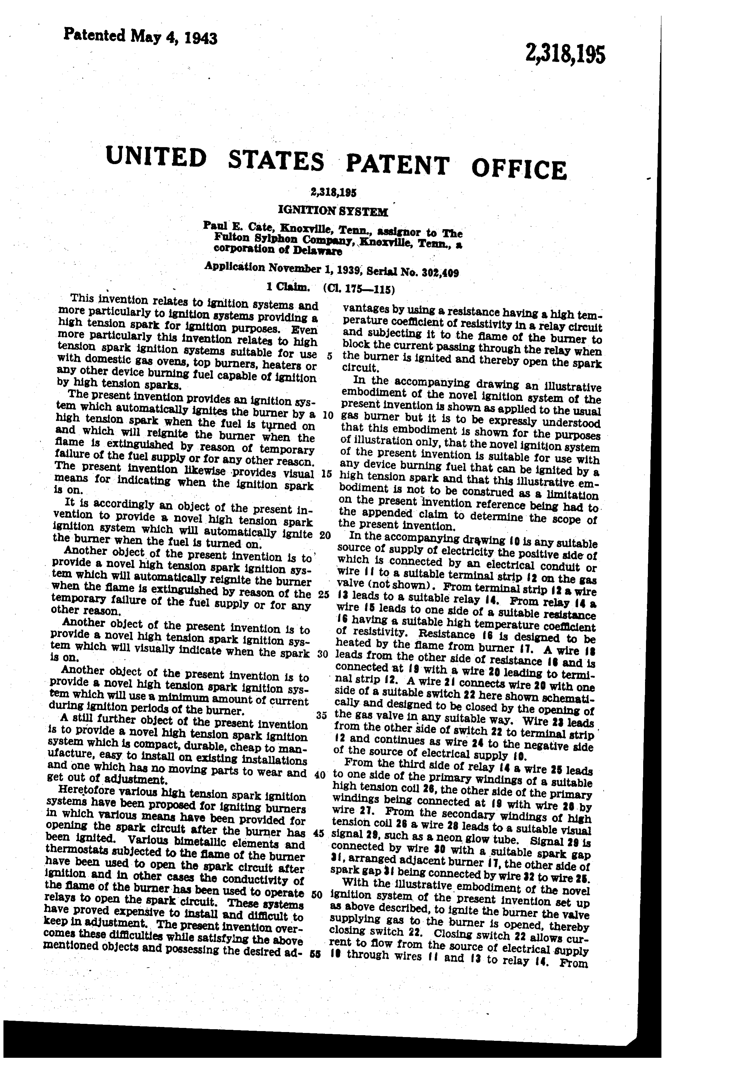
This invention relates to ignition systems and more particularly to ignition systems providing a vantages by using a resistancehaving a high tem high tension spark for ignition purposes. Even perature coefficient of resistivity in a relay circuit more particularly this invention relates to high and subjecting it to the flame of the burner to tension spark ignition systems suitable for use block the current passing through the relay when with domestic gas Ovens, top burners, heaters or the burner is ignited and thereby Open the spark circuit.
any other device burning fuel capable of ignition by high tension sparks. In the accompanying drawing an illustrative The present invention provides an ignition sys embodiment of the novel ignition system of the present ten which automatically ignites the burner by a 10 gas invention burner but itisisshown to beasexpressly applied tounderstood the usual high tension spark when the fuel is turned on that this embodiment is shown for the purposes and which will reignite the burner when the of illustration only, that the novel ignition system flame is extinguished by reason of temporary of the present invention is suitable for use with failure of the fuel supply or for any other reason. any device burning fuel that can be ignited by a The present invention likewise provides visualls high tension spark and that this illustrative em means for indicating when the ignition spark bodiment is not to be construed as a limitation is On. on the present invention reference being had to . It is accordingly an object of the present in- the appended claim to determine the scope of vention to provide a novel high tension spark the present invention.
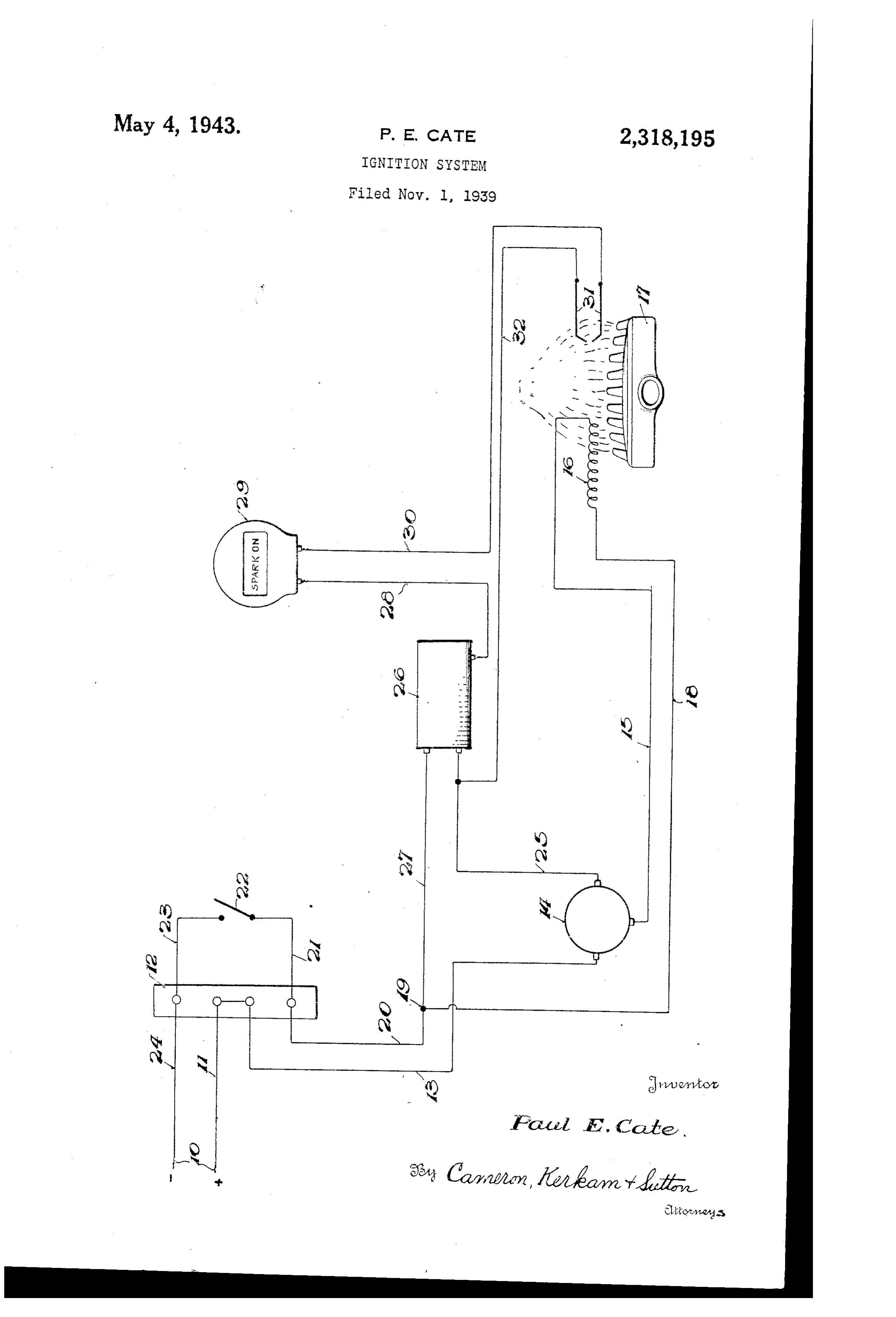
ignition system which will automatically ignite 20 In the accompanying drawing O is any suitable the burner when the fuel is turned on. source of supply of electricity the positive side of Another object of the present invention is to which is connected by an electrical conduit or provide a novel high tension spark ignition sys- wire to a suitable terminal strip 2 on the gas ten which will automatically reignite the burner valve (not shown). From terminal strip 2 a wire when the flame is extinguished by reason of the 25 3 leads to a suitable relay 4. From relay 4 a. temporary failure of the fuel supply or for any wire 5 leads to one side of a suitable resistance other reason. 6 having a suitable high temperature coefficient Another object of the present invention is to of resistivity. Resistance f6 is designed to be provide a novel high tension spark ignition sys- heated by the flame from burner . A wire B ten which will visually indicate when the spark 30 leads from the other side of resistance and is is on. . .. connected at 9 with a wire 20 leading to termi Another object of the present invention is to nal strip 2. A wire 2 connects wire 20 with one provide a novel high tension spark ignition sys- side of a suitable switch 22 here shown schemati tem which will use a minimum amount of current cally and designed to be closed by the opening of during ignition periods of the burner. 35 the gas valve in any suitable way. Wire 23 leads A still further object of the present invention from the other side of switch 22 to terminal strip is to provide a novel high tension spark ignition 2 and continues as wire 24 to the negative side system which is compact, durable, cheap to man- of the source of electrical supply 0. ufacture, easy to install on existing installations From the third side of relay 4 a wire 25 leads and one which has no moving parts to wear and 40 to one side of the primary windings of a suitable get out of adjustment. high tension coil 26, the other side of the primary Heretofore various high tension spark ignition windings being connected at 9 with wire 28, by systems have been proposed for igniting burners wire 2. From the secondary windings of high in which various means have been provided for tension coil 26 a wire 28 leads to a suitable visual opening the spark circuit after the burner has 45 signal 29, such as a neon glow tube. Signal 29 is been ignited. Various bimetallic elements and connected by wire 30 with a suitable spark gap thermostats subjected to the fame of the burner , arranged adjacent burner T, the other side of have been used to open the spark circuit after spark gap being connected by wire 32 to wire 25. ignition and in other cases the conductivity of With the illustrative embodiment of the novel the flame of the burner has been used to operate 50 ignition system of the present invention set up relays to open the spark circuit. These systems as above described, to ignite the burner the valve have proved expensive to install and difficult to supplying gas to the burner is opened, thereby keep in adjustment. The present invention over- closing switch 22. Closing switch 22 allows cur comes these difficulties while satisfying the above rent to flow from the source of electrical supply mentioned objects and possessing the desired ad- 55 through wires f and 3 to relay 4. From
Page 3
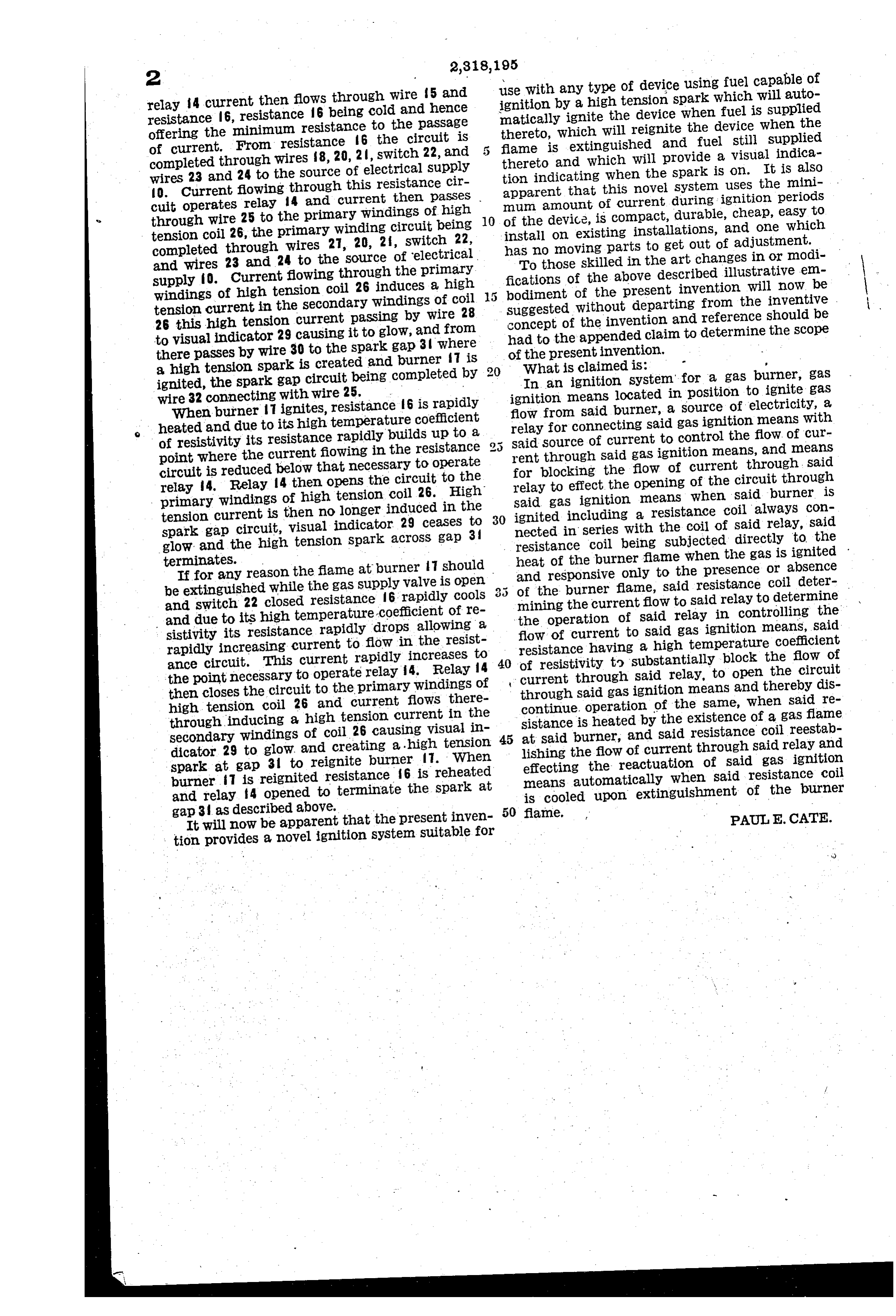
use with any type of device using fuel capable of relay 4 current then flows through wire 5 and ignition by a high tension spark which will auto resistance 6, resistance 6 being cold and hence matically ignite the device when fuel is supplied offering the minimum resistance to the paSSage thereto, which will reignite the device when the of current. From resistance 6 the circuit is flame is extinguished and fuel still supplied completed through wires 8, 20, 2, Switch 22, and thereto and which Will provide a visual indica wires 23 and 24 to the Source of electrical Supply tion indicating when the Spark is on. It is also O. Current flowing through this resistance cir apparent that this novel system uses the mini cuit operates relay 4 and current then passes nun amount of current during signition periods through wire 25 to the primary windings of high 10 of the device, is compact, durable, cheap, easy to tension coil 26, the primary winding circuit being install on existing installations, and one which completed through wires 27, 20, 2, switch 22, has no moving parts to get out of adjustment. and wires 23 and 24 to the source of electrical To those skilled in the art changes in or modi supply fo. Current flowing through the primary fications of the above described illustrative em windings of high tension coil 26 induces a high bodiment of the present invention will now be tension current in the secondary windings of coil Suggested Without departing from the inventive 26 this high tension current passing by wire 28 concept of the invention and reference should be to visual indicator 29 causing it to glow, and from had to the appended claim to determine the scope there passes by wire 30 to the spark gap 3 where of the present invention, a high tension Spark is created and burner 7 is What is claimed is: p ignited, the Spark gap circuit being completed by In an ignition System" for a gas burner, gas wire 32 connecting with wire 25. ignition means located in position to ignite gas When burner Tignites, resistance 6 is rapidly flow from said burner, a source of electricity, a heated and due to its high temperature coefficient relay for connecting said gas ignition means with of resistivity its resistance rapidly builds up to a 25 Said Source of current to control the flow of cur point where the current fowing in the resistance rent through said gas ignition means, and means circuit is reduced below that necessary to operate for blocking the flow of current through, said relay 4. Relay 4 then opens the circuit toHigh the relay to effect the opening of the circuit through primary windings of high tension coil 26. Said gas ignition means when said burner is tension current is then no longer induced in the 30 ignited including a resistance coil always con Spark gap circuit, visual indicator 29 ceases to nected in series with the coil of said relay, said glow and the high tension spark across gap 3 resistance coil being subjected directly to the terminates. heat of the burner flame when the gas is ignited If for any reason the fame at burner 7 should and responsive only to the presence or absence be extinguished while the gas supply valve is open 3 5 of the burner flame, said resistance coil deter and Switch 22 closed resistance 6 rapidly cools mining the current flow to said relay to determine and due to its high temperature-coefficient of re the operation of said relay in controlling the sistivity its resistance rapidly drops allowing a flow of current to said gas ignition means, said rapidly increasing current to flow in the resist resistance having a high temperature coefficient ance circuit. This current rapidly increases to 40 of resistivity to substantially block the flow of the point necessary to operate relay 4. Relay 4 current through said relay, to open the circuit then closes the circuit to the primary windings of through said gas ignition means and thereby dis high tension coil 26 and current flows there continue. Operation of the same, when said re through inducing a high tension current in the sistance is heated by the existence of a gas flame Secondary windings of coil 26 causing visual in at Said burner, and said resistance coil reestab dicator 29 to glow and creating a high tension 45 lishing the flow of current through said relay and spark at gap 31 to reignite burner f7. When effecting the reactuation of said gas ignition burner f7 is reignited resistance f6 is reheated means automatically when said resistance coil and relay 4 opened to terminate the spark at is cooled upon extinguishment of the burner gap 3 as described above.
It will now be apparent that the present inven 50 flane. PAUL E. CATE. tion provides a novel ignition system suitable for
Provenance
- Collection
- Cited prior art
- Original PDF
- patentimages.storage.googleapis.com →
- Filed
- 1939-11-01
- Pages
- 3
- Method
- pdftotext (the PDF's own text layer) + pdftoppm 300dpi page scans
- Source
- Google Patents bibliographic record
- Granted
- 1943-05-04
- Inventors
- Paul E Cate; Fulton Sylphon Co
- Transcribed from
- patentimages.storage.googleapis.com →