patent · US3196929
Ignition and control system for gas-fueled heating devices
27 July 1965
Page 1
Drawing sheet — no readable text.
Page 2
Drawing sheet — no readable text.
Page 3
Drawing sheet — no readable text.
Page 4
United States Patent Office 3,196,929 Paterated July 27, 1965
it has proved to be rather slow in igniting the fuel and 3.96,929 thus allows more unburned fuel to escape from the main
IGNITION AND CONTROL SYSTEM FOR burner than is desirable.
GAS-FUELEED HEATING EVECES A far more rapid system of ignition is achieved by (Cares I./Sier and Pa? Roaa Baeli, Bronx, N.Y., assiggs's 5 mounting the electrically actuated ignition device adjacent to Raisa Domestic Prodi cis Company, Eaglewood, N.S., to the main burner so as to be in directly igniting proX a partiership imity thereto, thus dispensing entirely with the wasteful Fied Apr. 25, 1966), Ser. No. 24.299 and slow pilot light. Electrically actuated ignition de 4. Caias. (C. 158-24) vices, which generally comprise some sort of high resist ance heated by the passage of an electric current there
The present invention relates generally to gas-fueled through, are capable of far exceeding the burning temper heating devices Such as furnaces, automatic clothes driers, ature of a typical gaseous fuel, which is around 1700 F. and the like, and in particular to an improved ignition A pilot burner fueled by the same gas necessarily achieves and control System for use with such heating devices. igniting temperatures of the same order. In contrast, the Recent changes in the safety standards for gas-fueled 15 type of electrically actuated ignition device commonly heating devices such as furnaces, clothes driers, and the referred to as a “glow coil' is capable of achieving ignition like, have placed great emphasis on speed of ignition. temperatures in the neighborhood of 2200–2400 F. With The object is to achieve ignition as rapidly as possible ignition temperatures of this order present in directly ignit after the gaseous fuel has begun to flow through the burner ing proximity to the main burner, as soon as the first So as to prevent spillage of unburned fuel into the area 20 “wave front' of fuel gas emerges from the main burner around the heating device. The mixture of combustible and approaches the nearby glow coil, nearly instantaneous fuel gases and atmospheric oxygen may be highly explo ignition thereof will take place. sive. The possibility most feared is that an ignition sys It is therefore specifically an object of this invention to tem which operates with a substantial time delay may at provide a novel direct ignition system in which an electri first permit quantities of unburned gaseous fuel to escape 25 cally actuated ignition device is placed in directly igniting from the burner to produce an explosive mixture, and then proximity to the main burner so as to perform the func later ignite the escaped fuel to cause a disastrous explo tion of igniting the main burner directly and with a mini sion. In addition to the problem of spillage of unburned mum of delay.
fuel occurring upon initial ignition of the heating device, Another object is to provide an ignition system which there are also various problems occasioned by different 30 conserves fuel by eliminating the continuously burning types of ignition system malfunctions which may cause pilot light.
Spillage during subsequent operation when the flow of fuel A further object of this invention is to provide associated is turied off and then on again, for example in response energizing circuitry and operating components to form a to normal operating conditions such as thernostatic or control system cooperating with the ignition device to pre timer control. Therefore, it is extremely important to 3 5 vent spillage of fuel during the occurrence of a wide vari develop an ignition system which always operates to ignite ety of operating conditions.
gaseous fuel with the least possible delay after the flow of Advantageously, it has been found that eXtremely effec fuel to the burner has started, and which also is effective tive protection against spillage can be provided in the at each and every stage of operation of the heating device environment of a direct ignition system with the use of to prevent spillage of unburned gaseous fuel. 40 fewer relays than would normally be required by prior Accordingly, it is broadly an object of this invention to art systems. Accordingly, it is an additional object of provide an improved ignition and control system for vari this invention to provide an ignition system designed to ous types of heating devices, particularly those burning anticipate a great variety of normal and abnormal condi gaseous fuel, which will prevent the spillage of unburned tions which may lead to the spillage of unburned fuel and fuel. More particularly, it is an object of this invention 45 to correct for such conditions to prevent such Spillage, at to prevent such spillage by providing an ignition System the same time achieving a considerable Saving in circuitry which is capable of extremely rapid ignition once the fuel and components.
has been allowed to fow through the burner. In accordance with an illustrative embodiment demon in the past, most commercial ignition systems employed strating additional objects and advantages of this inven in conjunction with heating devices that burn gaseous tion, there is provided an ignition system for use with a fiel have been of the type including a gas-fueled main heating device which has a burner fed through a fuel burner which provides the operating heat and a gas-fueled hasline governed by a fuel valve which is biased closed and pilot light burner which is mounted adjacent to the main system electrically actuated opening means. The ignition burner So as to be in igniting proximity thereto. The re 5 5 in accordance with this invention comprises means mainder of such an ignition system has typically included for preventing spillage of unburned fuel including a means, usually electrically actuated, for igniting the pilot switch which has a fuel-feeding position and an electrical light and for controlling the fow of fuel to the pilot light operating circuit connected to energize the valve-opening and the main burier. Such systems also have typically in means for opening the fuel valve only when the Switch is in the aforesaid fuel-feeding position. Means are fur ciuded a fairly complex system of safety relays designed to 60 ther provided for preventing the Switch from assuming prevent spillage of unburned fuel during normal operation, its fuel-feeding position unless the fuel will encounter and to some extent also during malfunction, of the heating a fuel-ignition temperature. A thermally responsive device and the ignition system. It is characteristic of such member is mounted in temperature-sensing proximity to prior art ignition systems that the pilot light remains lit the burner, and means are operatively connected to move during continued normal operation of the heating device 65 the switch out of its fuel-feeding position to prevent the and serves to ignite the main burner whenever the latter fiow of fuel in response to contraction of the thermally is then turned off and on again in the course of a normal responsive member when the latter senses the absence operating cycle. This system of lighting the main burner of a fuel-ignition temperature at the burner. through the intermediary of a pilot burner, which we may The foregoing brief summary, as well as additional refer to as indirect ignition, is wasteful of fuel because advantageous features of this invention, may best be the pilot burner is continuously in operation. In addition, appreciated by reference to the following detailed de
Page 5
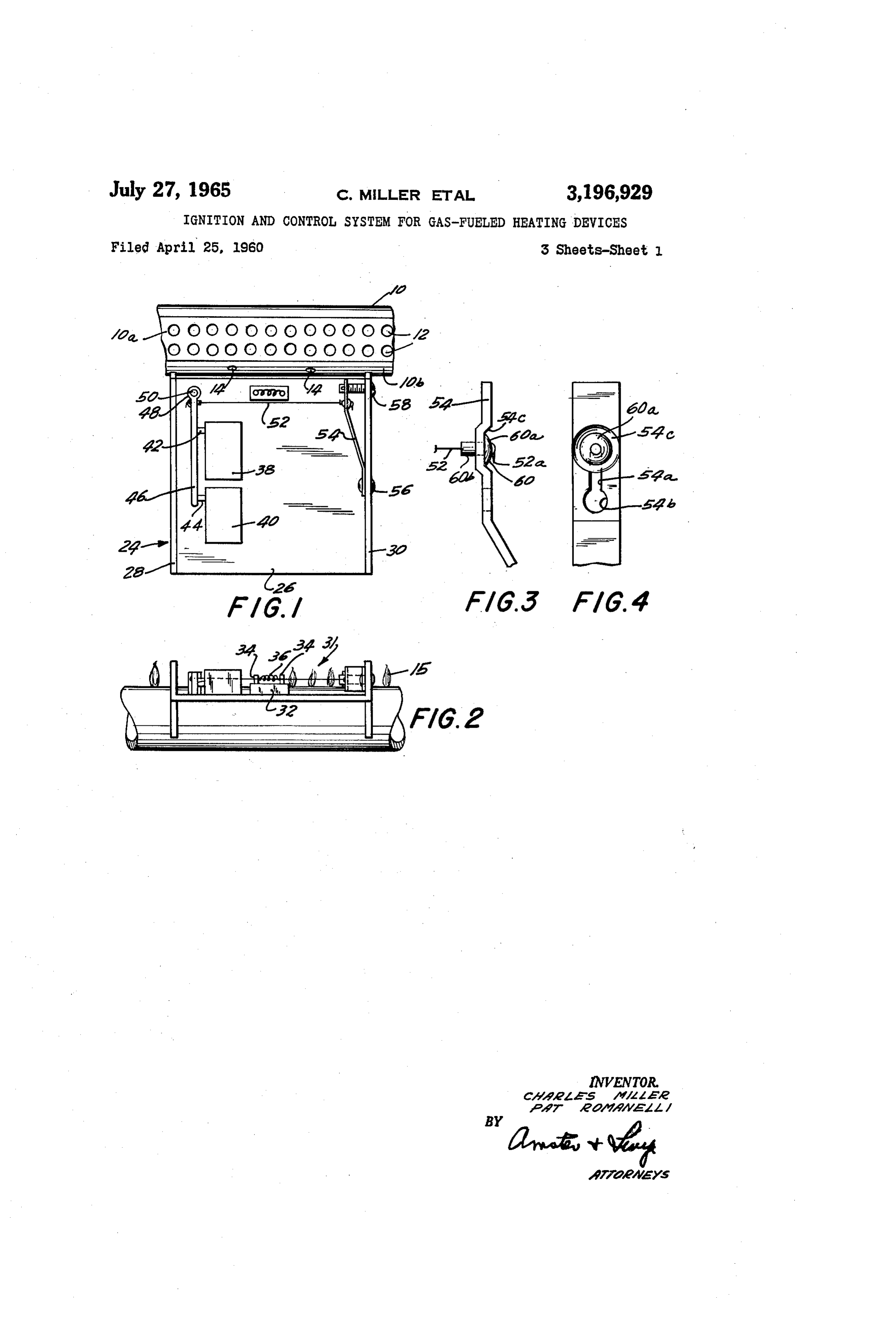
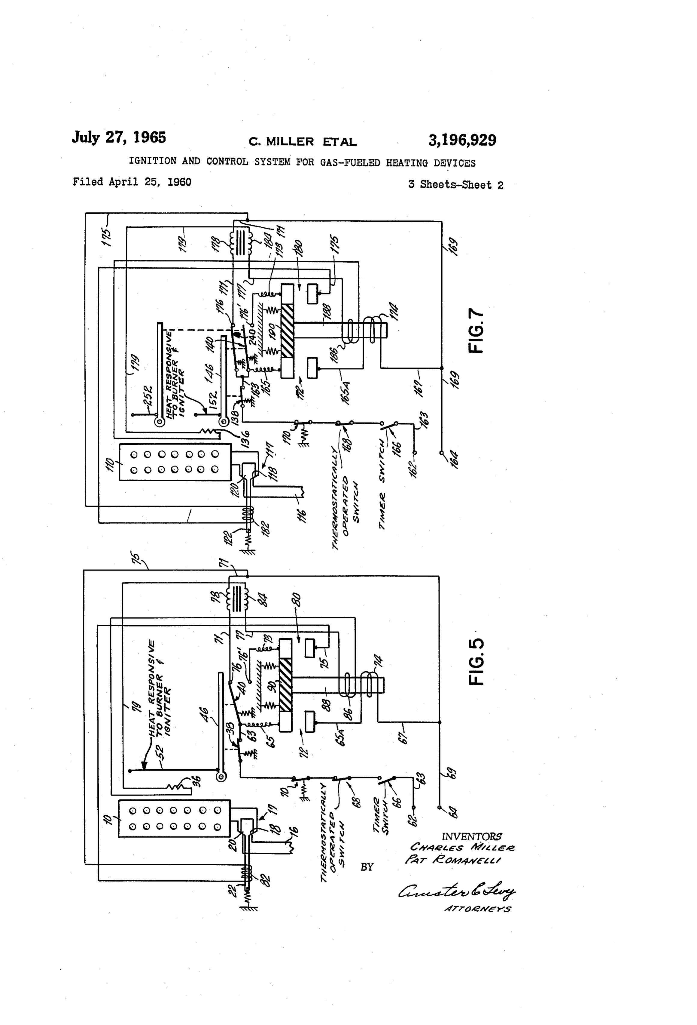
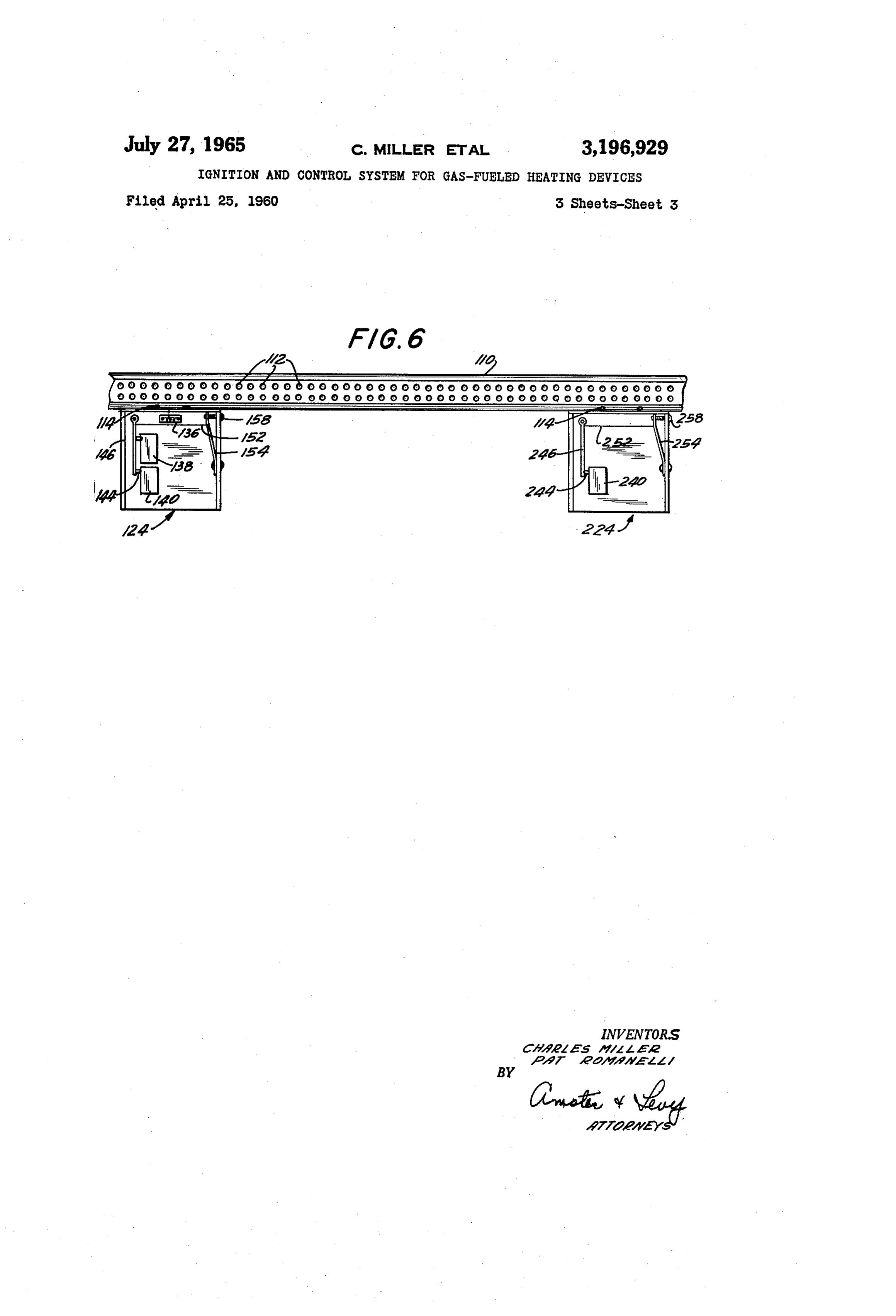
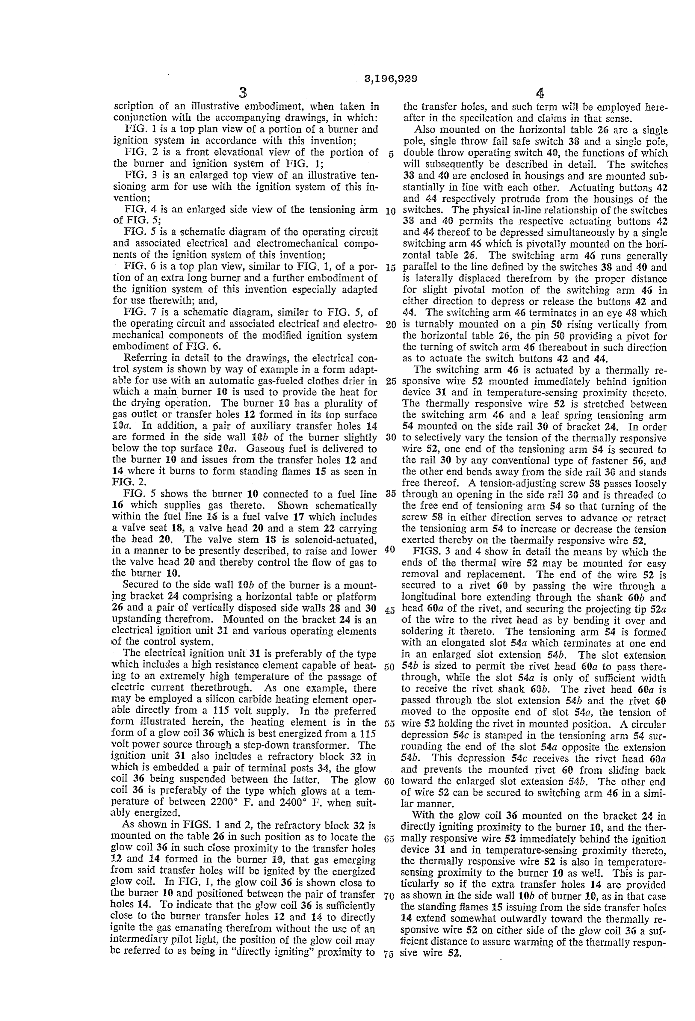
scription of an illustrative embodiment, when taken in the transfer holes, and such term will be employed here conjunction with the accompanying drawings, in which: after in the specification and claims in that sense. FIG. 1 is a top plan view of a portion of a burner and Also mounted on the horizontal table 26 are a single ignition system in accordance with this invention; pole, single throw fail safe switch 38 and a single pole, FIG. 2 is a front elevational view of the portion of 5 double throw operating switch 40, the functions of which the burner and ignition system of FIG. 1; will subsequently be described in detail. The switches FIG. 3 is an enlarged top view of an illustrative ten 33 and 40 are enclosed in housings and are mounted sub sioning arm for use with the ignition system of this in stantially in line with each other. Actuating buttons 42 vention; and 44 respectively protrude from the housings of the FIG. 4 is an enlarged side view of the tensioning arm 0. switches. The physical in-line relationship of the switches of FIG. 5; 33 and 48 permits the respective actuating buttons 42 FiG. 5 is a schematic diagram of the operating circuit and 44 thereof to be depressed simultaneously by a single and associated electrical and electromechanical compo Switching arm 46 which is pivotally mounted on the hori nents of the ignition system of this invention; Zontal table 26. The switching arm 46 runs generally FiG. 6 is a top plan view, sinuilar to FIG. 1, of a por 5 parallel to the line defined by the switches 38 and 49 and tion of an extra long burner and a further embodiment of is laterally displaced therefrom by the proper distance the ignition system of this invention especially adapted for slight pivotal motion of the switching arm 46 in for use therewith; and, either direction to depress or release the buttons 42 and FIG. 7 is a schematic diagram, similar to FIG. 5, of 44. The switching arm 46 terminates in an eye 48 which the operating circuit and associated electrical and electro 20 is turnably mounted on a pin 50 rising vertically from mechanical components of the modified ignition system the horizontal table 26, the pin 50 providing a pivot for embodiment of FIG. 6. the turning of switch arm 46 thereabout in such direction Referring in detail to the drawings, the electrical con as to actuate the switch buttons 42 and 44. trol System is shown by way of example in a form adapt The switching arm 46 is actuated by a thermally re able for use with an automatic gas-fueled clothes drier in 25 sponsive wire 52 mounted immediately behind ignition which a main burner 10 is used to provide the heat for device 3; and in temperature-sensing proximity thereto. the drying operation. The burner 10 has a plurality of The thermally responsive wire 52 is stretched between gas outlet or transfer holes 12 formed in its top surface the switching arm 46 and a leaf spring tensioning arm Sea. In addition, a pair of auxiliary transfer holes 14 54 mounted on the side rail 36 of bracket 24. In order are formed in the side wall Cb of the burner slightly 30 to selectively vary the tension of the thermally responsive below the top surface 10a. Gaseous fuel is delivered to wire 52, one end of the tensioning arm 54 is secured to the burner 10 and issues from the transfer holes 12 and the rail 30 by any conventional type of fastener 56, and 14 where it burns to form standing flames 15 as seen in the other end bends away from the side rail 36 and stands FIG. 2. free thereof. A tension-adjusting screw 58 passes loosely FIG. 5 shows the burner 10 connected to a fuel line 35 through an opening in the side rail 30 and is threaded to 16 which supplies gas thereto. Shown schematically the free end of tensioning arm 54 so that turning of the within the fuel line 6 is a fuel valve 17 which includes screw 58 in either direction serves to advance or retract a valve seat 18, a valve head 20 and a stem 22 carrying the tensioning arm 54 to increase or decrease the tension the head 20. The valve stem 18 is solenoid-actuated, exerted thereby on the thermally responsive wire 52. in a manner to be presently described, to raise and lower 40 FIGS. 3 and 4 show in detail the means by which the the valve head 20 and thereby control the flow of gas to ends of the thermal wire 52 may be mounted for easy the burner 0. removal and replacement. The end of the wire 52 is Secured to the side wall 10b of the burner is a mount Secured to a rivet 60 by passing the wire through a ing bracket 24 comprising a horizontal table or platform longitudinal bore extending through the shank 60b and 26 and a pair of vertically disposed side walls 28 and 30 head 60a of the rivet, and securing the projecting tip 52a upstanding therefrom. Mounted on the bracket 24 is an of the wire to the rivet head as by bending it over and electrical ignition unit 31 and various operating elements soldering it thereto. The tensioning arm 54 is formed of the control system. with an elongated slot 54a which terminates at one end The electrical ignition unit 31 is preferably of the type in an enlarged slot extension 54b. The slot extension which includes a high resistance element capable of heat 54b is sized to permit the rivet head 60a to pass there ing to an extremely high temperature of the passage of through, while the slot 54a is only of sufficient width electric current therethrough. As one example, there to receive the rivet shank 66b. The rivet head 60a is may be employed a silicon carbide heating element oper passed through the slot extension 54b and the rivet 60 able directly from a 115 volt supply. In the preferred moved to the opposite end of slot 54a, the tension of form illustrated herein, the heating element is in the wire 52 holding the rivet in mounted position. A circular form of a glow coil 36 which is best energized from a 115 depression 54c is stamped in the tensioning arm 54 sur volt power source through a step-down transformer. The rounding the end of the slot 54a opposite the extension ignition unit 31 also includes a refractory block 32 in 54b. This depression 54c receives the rivet head 60a which is embedded a pair of terminal posts 34, the glow and prevents the mounted rivet 60 from sliding back coil 36 being suspended between the latter. The glow 60 toward the enlarged slot extension 54b. The other end coil 36 is preferably of the type which glows at a tem of wire 52 can be secured to switching arm 46 in a simi perature of between 2200 F. and 2400 F. When suit lar manner.
ably energized. With the glow coil 36 mounted on the bracket 24 in As shown in FIGS. 1 and 2, the refractory block 32 is directly igniting proximity to the burner 10, and the ther mounted on the table 26 in such position as to locate the mally responsive wire 52 immediately behind the ignition glow coil 36 in such close proximity to the transfer holes device 31 and in temperature-sensing proximity thereto, 12 and 4 formed in the burner 10, that gas emerging the thermally responsive wire 52 is also in temperature from said transfer holes will be ignited by the energized sensing proximity to the burner 10 as well. This is par glow coil. In FIG. 1, the glow coil 36 is shown close to ticularly so if the extra transfer holes 14 are provided the burner 10 and positioned between the pair of transfer 70 as shown in the side wall 10b of burner 10, as in that case holes 14. To indicate that the glow coil 36 is sufficiently the standing flames 15 issuing from the side transfer holes close to the burner transfer holes 12 and 14 to directly 14 extend somewhat outwardly toward the thermally re ignite the gas emanating therefrom without the use of an sponsive wire 52 on either side of the glow coil 36 a suf intermediary pilot light, the position of the glow coil may ficient distance to assure warming of the thermally respon be referred to as being in "directly igniting” proximity to sive wire 52.
Page 6
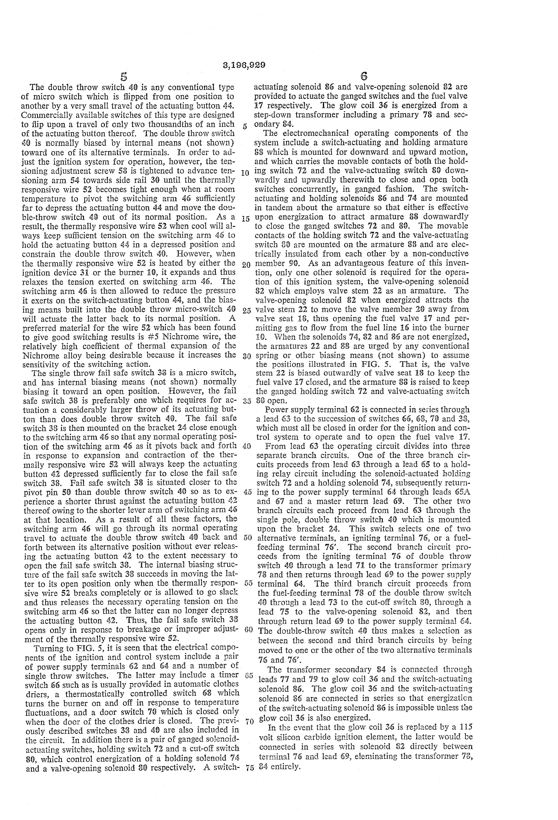
The double throw Switch 40 is any conventional type actuating solenoid 86 and valve-opening solenoid 82 are of micro switch which is flipped from one position to provided to actuate the ganged switches and the fuel valve another by a very small travel of the actuating button 44. 17 respectively. The glow coil 36 is energized from a Commercially available switches of this type are designed step-down transformer including a primary 78 and sec to flip upon a travel of only two thousandths of an inch 5 ondary 84.
of the actuating button thereof. The double throw switch The electromechanical operating components of the 46) is normally biased by internal means (not shown) system include a switch-actuating and holding armature toward one of its alternative terminals. In order to ad SS which is mounted for downward and upward motion, just the ignition system for operation, however, the ten and which carries the movable contacts of both the hold sioning adjustment screw 53 is tightened to advance ten O ing switch 72 and the valve-actuating switch 80 down sioning arm 54 towards side rail 30 until the thermally wardly and upwardly therewith to close and open both responsive wire 52 becomes tight enough when at room switches concurrently, in ganged fashion. The Switch temperature to pivot the switching arim 46 sufficiently actuating and holding solenoids 86 and 74 are mounted far to depress the actuating button 44 and move the dou in tandem about the armature so that either is effective ble-throw switch 43 out of its normal position. As a 5 upon energization to attract armature 88 downwardly result, the thermally responsive wire 52 when cool will al to close the ganged switches 72 and 88. The movable ways keep sufficient tension on the switching arm 46 to contacts of the holding switch 72 and the valve-actuating hold the actuating button 44 in a depressed position and switch 39 are mounted on the armature 38 and are elec constrain the double throw switch 49. However, when trically insulated from each other by a non-conductive the thermally responsive wire 52 is heated by either the 20 member 90. As an advantageous feature of this inven ignition device 31 or the burner EC, it expands and thus tion, only one other solenoid is required for the opera relaxes the tension exerted on switching arm 46. The tion of this ignition system, the valve-opening solenoid switching artin 46 is then allowed to reduce the pressure 82 which employs valve stem 22 as an armature. The it exerts on the switch-actuating button 44, and the bias valve-opening solenoid 82 when energized attracts the ing means built into the double throw micro-switch 46 5 valve stein 22 to move the valve member 20 away from wiil actuate the latter back to its normal position. A valve seat 8, thus opening the fuel valve 87 and per preferred material for the wire 52 which has been found initting gas to flow from the fuel line 6 into the burner to give good switching results is iF5 Nichrome wire, the E.). When the Solenoids 74, 82 and 86 are not energized, relatively high coefficient of thermal expansion of the the armatures 22 and 33 are urged by any conventional Nichrome alloy being desirable because it increases the spring or other biasing means (not shown) to assume sensitivity of the switching action. the positions illustrated in FIG. 5. That is, the valve The single throw fail safe switch 38 is a micro Switch, stem 22 is biased outwardly of valve seat 8 to keep the and has internal biasing means (not shown) normally fuel valve 97 closed, and the armature 88 is raised to keep biasing it toward an open position. However, the fail the ganged holding switch 72 and valve-actuating Switch safe switch 38 is preferably one which requires for ac 3. 5 84 oper.
tuation a considerably larger throw of its actuating but Power supply terminal 62 is connected in seities through ton than does double throw switch 49. The fail Safe a lead 63 to the Succession of Switches 66, 63, i3 and 33, switch 33 is then mounted on the bracket 24 close enough which must all be closed in order for the ignition and con to the switching arm 45 so that any normal operating posi trol system to operate and to open the fuel valve 17. tion of the switching arm 46 as it pivots back and forth 40 From lead 63 the operating circuit divides into three in response to expansion and contraction of the ther separate branch circuits. One of the three branch cir maily responsive wire 52 will always keep the actuating cuits proceeds from lead 63 through a lead 65 to a hold button 42 depressed sufficiently far to close the fail Safe ing relay circuit including the solenoid-actuated holding switch 38. Fail safe switch 38 is situated closer to the Switch 72 and a holding Solenoid 74, Subsequently return pivot pin 50 than double throw switch 40 so as to ex ing to the power supply terminal 64 through leads 65A perience a shorter thrust against the actuating button 42 and 67 and a master return lead 69. The other two thereof owing to the shorter lever arm of Switching arm 45 branch circuits each proceed from lead 63 through the at that location. As a result of all these factors, the single pole, double throw switch 42 which is mounted switching arm 46 will go through its normal operating upon the bracket 24. This switch selects one of two travel to actuate the double throw switch 40 back and alternative terminals, an igniting terminal 76, or a fuel forth between its alternative position without ever releas feeding terminal 76". The second branch circuit pro ing the actuating button 42 to the extent necessary to ceeds from the igniting terminal 76 of double throw open the fail safe switch 33. The internal biasing struc switch 49 through a lead 7 to the transformer primary are of the fail safe switch 38 succeeds in moving the lat 73 and then returns through lead 63 to the power supply ter to its open position only when the thermally respon 5 terminal 64. The third branch circuit proceeds from sive wire 52 breaks completely or is allowed to go slack the fuel-feeding terminal 78 of the double throw switch and thus releases the necessary operating tension on the 4 through a lead 73 to the cut-off switch 38, through a switching arm 46 so that the latter can no longer depress lead 75 to the valve-opening solenoid 82, and then the actuating button 42. Thus, the fail safe Switch 38 through return lead 69 to the power supply terminal 64. opens only in response to breakage or improper adjust 60 The double-throw switch 49 thus makes a selection as ment of the thermally responsive wire 52. between the second and third branch circuits by being Turning to FIG. 5, it is seen that the electrical compo moved to one or the other of the two alternative terminals nents of the ignition and control System include a pair 76 and 5.
of power supply terminals 62 and 64 and a number of The transformer secondary 84 is connected through single throw switches. The latter may include a timer 6 5 leads 77 and 79 to glow coil 35 and the switch-actuating switch 66 such as is usually provided in automatic clothes driers, a thermostatically controlled Switch 68 which solenoid 86.
solenoid
The glow coil 36 and the switch-actuating are connected in series so that energization turns the burner on and off in response to temperature fluctuations, and a door switch 70 which is closed only of the switch-actuating solenoid 86 is impossible linless the glow coil 36 is also energized.
when the door of the clothes drier is closed. The previ ously described switches 33 and 40 are also included in voltIn silicon the event that the glow coil 36 is replaced by a 115 carbide ignition element, the latter would be the circuit. In addition there is a pair of ganged solenoid connected in Series with Solenoid 82 directly between actuating switches, holding switch 72 and a cut-off Switch terrigal 80, which control energization of a holding Solenoid 74 84 entirely. 76 and lead 659, eleminating the transformer 78, and a valve-opening solenoid 89 respectively. A switch
Page 7
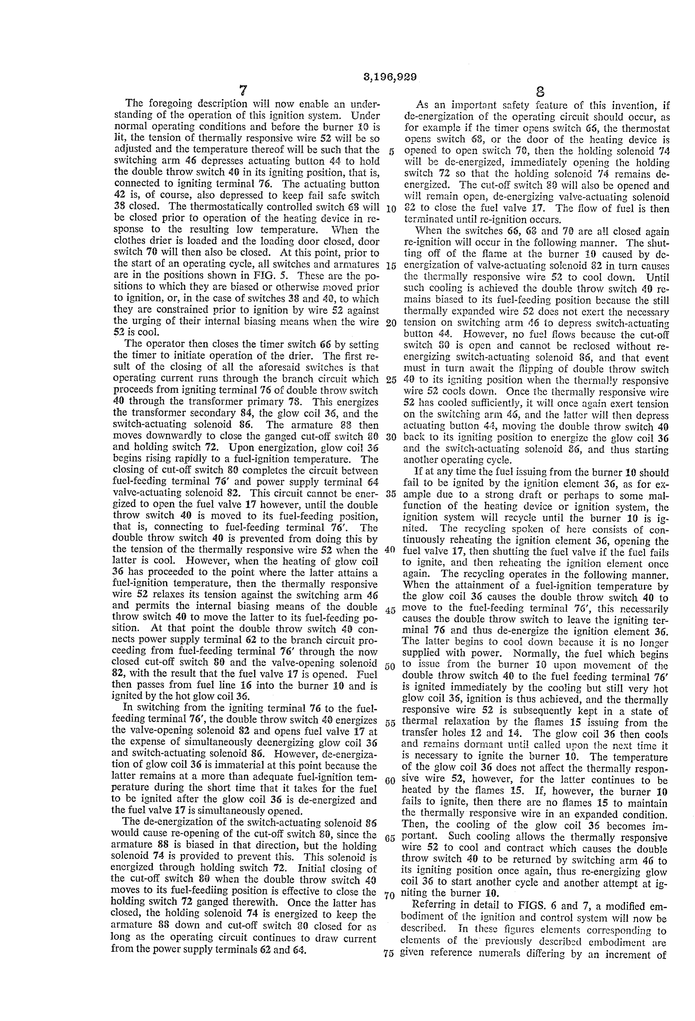
The foregoing description will now enable an under As an important safety feature of this invention, if standing of the operation of this ignition system. Under de-energization of the operating circuit should occur, as normal operating conditions and before the burner () is for example if the timer opens switch 66, the thermostat lit, the tension of thermally responsive wire 52 will be so opens switch 68, or the door of the heating device is adjusted and the temperature thereof will be such that the opened to open switch 70, then the holding solenoid 74 switching arm 46 depresses actuating button 44 to hold will be de-energized, immediately opening the holding the double throw switch 40 in its igniting position, that is, switch 72 so that the holding Solenoid 14 remains de connected to igniting terminal 76. The actuating button energized. The cut-off Switch 33 will also be opened and 42 is, of course, also depressed to keep fail safe switch will remain open, de-energizing valve-actuating solenoid 38 closed. The thermostatically controlled switch 63 will O 32 to close the fuel valve 7. The flow of fuel is then be closed prior to operation of the heating device in re terrinated until re-ignition occurs. sponse to the resulting low temperature. When the When the switches 66, 68 and 7i are all closed again clothes drier is loaded and the loading door closed, door re-ignition will occur in the following manner. The shut switch 70 will then also be closed. At this point, prior to ting off of the flame at the burner () caused by de the start of an operating cycle, all Switches and armatures energization of valve-actuating solenoid 82 in turn causes are in the positions shown in F.G. 5. These are the po the thermally responsive wire 52 to cool down. Until sitions to which they are biased or otherwise noved prior such cooling is achieved the double throw switch 40 re to ignition, or, in the case of switches 38 and 40, to which mains biased to its fuel-feeding position because the still they are constrained prior to ignition by wire 52 against thermally expanded wire 52 does not exert the necessary the urging of their internal biasing means when the wire 20 tension on Switching arm 6 to depress Switch-actuating 52 is cool. button 44. However, no fuel flows because the cut-off The operator then closes the timer switch 66 by setting switch 30 is open and cannot be reclosed without re the timer to initiate operation of the drier. The first re energizing switch-actuating solenoid 85, and that event sult of the closing of all the aforesaid switches is that must in turn await the flipping of double throw switch operating current runs through the branch circuit which 25 49 to its igniting position when the thermally responsive proceeds from igniting terminal 75 of double throw switch wire 52 cools down. Once the thermally responsive wire 40 through the transformer primary 78. This energizes 52 has cooled sufficiently, it will once again exert tension the transformer secondary 84, the glow coil 36, and the on the switching arm 46, and the latter will then depress switch-actuating solenoid 86. The armature 83 then actuating button 44, moving the double throw switch 40 moves downwardly to close the ganged cut-off switch 80 30 back to its igniting position to energize the glow coil 36 and holding switch 72. Upon energization, glow coil 36 and the Switch-actuating Solenoid 36, and thus starting begins rising rapidly to a fuel-ignition temperature. The another operating cycle.
closing of cut-off switch 80 completes the circuit between If at any time the fuel issuing from the burner 10 should fuel-feeding terminal 76' and power supply terminal 64 fail to be ignited by the ignition element 36, as for ex valve-actuating solenoid 82. This circuit cannot be ener 35 ample due to a strong draft or perhaps to some mal gized to open the fuel valve 17 however, until the double function of the heating device or ignition system, the throw switch 40 is moved to its fuel-feeding position, ignition system will recycle until the burner () is ig that is, connecting to fuel-feeding terminal 76'. The nited. The recycling spoken of here consists of con double throw switch 40 is prevented from doing this by tinuously reheating the ignition element 36, opening the the tension of the thermally responsive wire 52 when the 40 fuel valve 17, then shutting the fuel valve if the fuel fails latter is cool. However, when the heating of glow coil to ignite, and then reheating the ignition element once 36 has proceeded to the point where the latter attains a again. The recycling operates in the following manner. fuel-ignition temperature, then the thermally responsive When the attainment of a fuel-ignition temperature by wire 52 relaxes its tension against the switching arm 46 the glow coil 36 causes the double throw switch 40 to and permits the internal biasing means of the double move to the fuel-feeding terminal 76, this necessarily throw switch 40 to move the latter to its fuel-feeding po causes the double throw switch to leave the igniting ter sition. At that point the double throw switch 4, con minal 76 and thus de-energize the ignition element 36. nects power supply terminal 62 to the branch circuit pro The latter begins to cool down because it is no longer ceeding from fuel-feeding terminal 76' through the now Supplied with power. Normally, the fuel which begins closed cut-off switch 80 and the valve-opening solenoid to issue from the burner 18 upon movement of the 82, with the result that the fuel valve 17 is opened. Fuel double throw switch 40 to the fuel feeding terminal 76 then passes from fuel line i6 into the burner 0 and is is ignited immediately by the cooling but still very hot ignited by the hot glow coil 36. glow coil 36, ignition is thus achieved, and the thermally In switching from the igniting terminal 76 to the fuel responsive wire 52 is subsequently kept in a state of feeding terminal 76, the double throw switch 48 energizes thermal relaxation by the flames 5 issuing from the the valve-opening solenoid 82 and opens fuel valve 17 at transfer holes 2 and 4. The glow coil 36 then cools the expense of simultaneously deemergizing glow coil 36 and remains dormant until called upon the next time it and Switch-actuating solenoid 86. However, de-energiza is necessary to ignite the burner 10. The temperature tion of glow coil 36 is immaterial at this point because the of the glow coil 36 does not affect the thermally respon latter remains at a more than adequate fuel-ignition tem 60 sive wire 52, however, for the latter continues to be perature during the short time that it takes for the fuel heated by the flames 15. If, however, the burner 10 to be ignited after the glow coil 36 is de-energized and fails to ignite, then there are no flames 15 to maintain the fuel valve 7 is simultaneously opened. the thermally responsive wire in an expanded condition. The de-energization of the switch-actuating solenoid 86 Then, the cooling of the glow coil 35 becomes in would cause re-opening of the cut-off switch 80, since the portant. Such cooling allows the thermally responsive armature 88 is biased in that direction, but the holding wire 52 to cool and contract which causes the double solenoid 74 is provided to prevent this. This solenoid is throw switch 40 to be returned by switching arm 46 to encrgized through holding switch 72. Initial closing of its igniting position once again, thus re-energizing glow the cut-off switch 88 when the double throw switch 40 moves to its fuel-feeding position is effective to close the 70 niting the burneranother coil 36 to start
cycle and another attempt at ig holding switch 72 ganged therewith. Once the latter has Referring in detail to FIGS. 6 and 7, a modified em closed, the holding Solenoid 74 is energized to keep the bodiment of the ignition and control system will now be armature 88 down and cut-off switch 30 closed for as described. in these figures elements corresponding to long as the operating circuit continues to draw current elements of the previously described embodiment are from the power supply terminals 62 and 64. given reference numerals differing by an increment of
Page 8
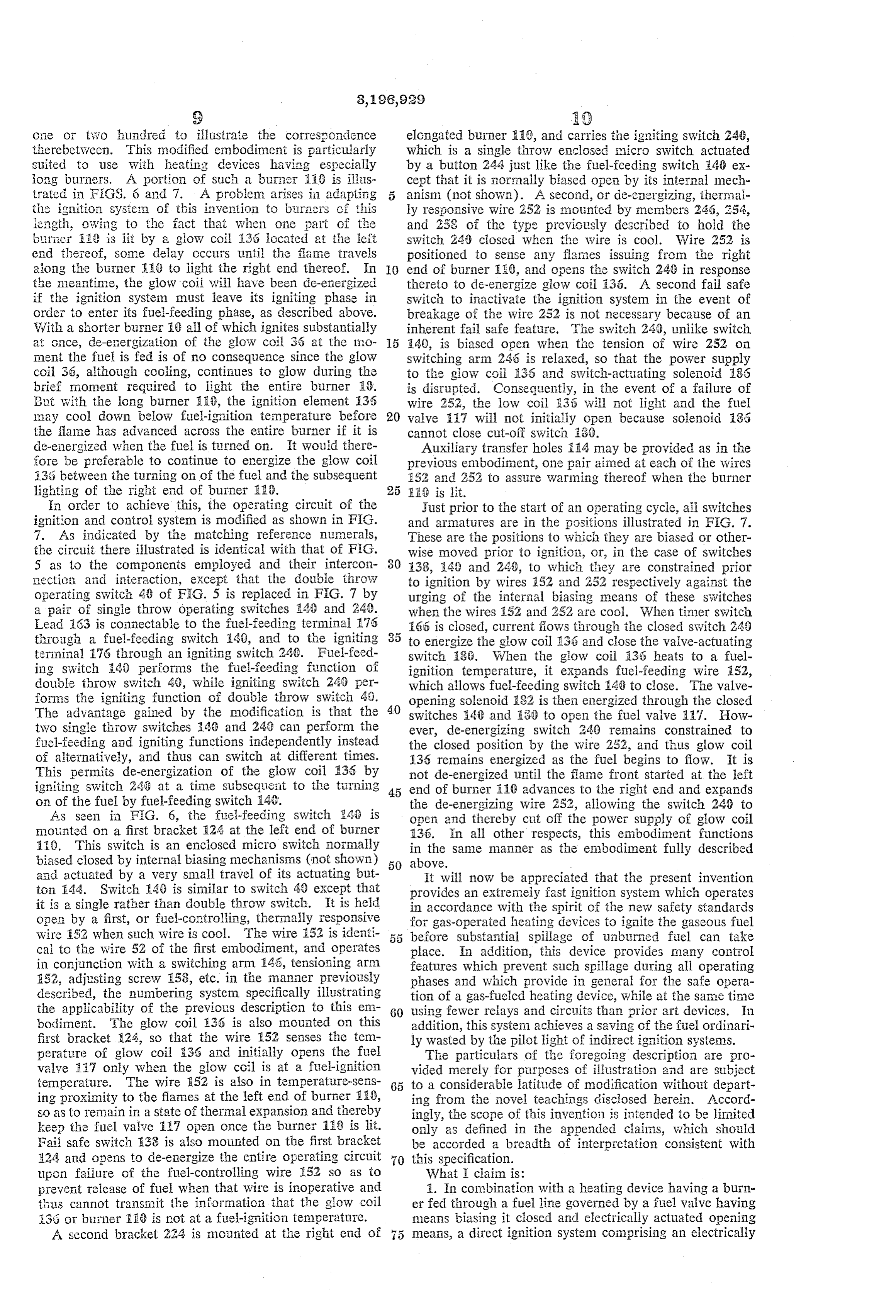
one or two hundred to illustrate the correscindence elongated burner ES6, and carries the igniting switch 24, therebetween. This nodified embodiment is particularly which is a single throw enclosed micro switch actuated Suited to use with heating devices having especially by a button 244 just like the fuel-feeding switch 40 ex iong burners. A portion of Such a burner Si3 is illus cept that it is normally biased open by its internal mech trated in FiOS. 6 and 7. A problem arises in adapting 5 anism (not shown). A second, or de-energizing, thermal the ignition systein of this investion to bi-racrs of this ly responsive wire 252 is mounted by members 246, 254, iength, owing to the fact that when one part of the and 258 of the type previously described to hoid the burier 18 is lit by a glow coil 33 located at the left Switch 24, closed when the wire is cool. Wire 252 is end thereof, some delay occurs until the fame travels positioned to sense any flanes issuing from the right along the burner its to light the right end thereof. In O end of burier 16, and opens the switch 24G in response the meantine, the glow coii will have been de-energized thereto to de-energize glow coil 35. A Second fail safe if the ignition system must leave its igniting phase in Switch to inactivate the ignition system in the event of order to enter its file-feeding phase, as described above. breakage of the wire 252 is not necessary because of an With a shorter burner AG ail of which ignites substantially inherent fail safe feature. The switch 24, unlike switch at Gince, de-energization of the glow coil 36 at the no E40, is biased open when the tension of wire 252 on ment the fuel is fed is of no consequence since the glow switching arm 243 is relaxed, so that the power supply coil 36, although cooling, continues to glow during the to the glow coii i35 and switch-actuating solenoid 35 brief moment required to light the entire burner 28. is disrupted. Consequently, in the event of a failure of But with the long burner is, the ignition element 35 wire 252, the low coil 33 will not light and the fuel may cool down below fuel-ignition te;mperature before 20 valve it will not initially open because solenoid E85 the flame has advanced across the entire burner if it is cannot close cut-off Switch 30. de-energized when the fuel is turned on. It would there Auxiliary transfer holes i4 may be provided as in the fore be preferable to continue to energize the glow coil previous enbodiment, one pair aimed at each of the wires E33 between the turning on of the fuei and the Subsequent :52 and 252 to assure warming thereof when the burner lighting of the right end of burner E33. EA 3 is lit.
in order to achieve this, the operating circuit of the Just prior to the start of an operating cycle, all switches ignition and control system is modified as shown in FG. and arimatures are in the gositions illustrated in FiG. 7. 7. As indicated by the matching reference nuinerals, These are the positions to which they are biased or other the circuit there illustrated is identical with that of FG. wise moved prior to ignition, or, in the case of switches 5 as to the components employed and their intercoil ;38, 43 and 243, to which they are constrained prior nectic aid interaction, except that the double throW to ignition by wires 52 and 252 respectively against the operating switch 43 of F.G. 5 is replaced in FIG. 7 by urging of the internal biasing means of these switches a pair of single throw operating switches 46 and 240. when the wires 52 and 252 are cool. When timer switch lead 263 is connectable to the fuel-feeding terminal 175 65 is ciosed, current flows through the closed switch 243 through a fuel-feeding Switch i40, and to the igniting 3 k to energize the glow coil 33 and close the valve-actuating terminal 76 through an igniting switch 249. Fuel-feed Switch 3G. When the glow coil 33 heats to a fuel ing switch 40 performs the fuel-feeding function of ignition temperature, it expands fuei-feeding wire i52, double throw switch 46, while igniting Switch 248 per which allows fuel-feeding switch 43 to close. The valve forms the igniting function of double throw Switch 43. opening solenoid 32 is then energized through the closed The advantage gained by the modification is that the 40 switches S4C and i3 to open the fuel valve Af. How two single throw switches 46 and 243 can perform the ever, de-energizing switch 248 remains constrained to fuel-feeding and igniting functions independently instead the closed position by the wire 252, and thus glow coil of aiternatively, and thus can switch at different times. E35 remains energized as the fuel begins to flow. It is This permits de-energization of the glow coil 135 by not de-energized until the fame front started at the left igniting Switch 243 at a time Subsequisint to the ti}}"ning end of burier E10 advances to the right end and expands on of the fuel by fuel-feeding switch 46. the de-energizing wire 2.52, allowing the switch 246 to As seen in F.G. 6, the fire-feeding switch 343 is open and thereby cut off the power Supply of glow coil mounted on a first bracket E24 at the left end of burner 136. In all other respects, this embodiment functions a G. This switch is an enclosed micro switch normally in the same manner as the embodiment fully described biased closed by internal biasing mechanisins (not shown) 50 above.
and actuated by a very small travel of its actuating but it will now be appreciated that the present invention ton 44. Switch 4G is similar to Switch 43 except that provides an extremeiy fast ignition system which operates it is a single rather than double throw switch. It is held in accordance with the spirit of the new safety standards open by a first, or fuel-controlling, therinally responsive for gas-operated heating devices to ignite the gaseous fuel wire 52 when such wire is cool. The wire 52 is identi before Substantial spillage of unburned fuel can take cal to the wire 52 of the first embodiment, and operates place. In addition, this device provides many control in conjunction with a switching arm E45, tensioning arr) features which prevent such spillage during all operating 252, adjusting screw 158, etc. in the manner previously phases and which provide in general for the safe opera described, the numbering system specifically illustrating tion of a gas-fueled heating device, while at the sane time the applicability of the previous description to this ena 60 using fewer relays and circuits than prior art devices. In bodiment. She glow coil 36 is also mounted on this addition, this system achieves a saving of the fiel ordinari first bracket 24, so that the wire 52 senses the ten ly wasted by the pilot light of indirect ignition systems. perature of glow coil E.36 and initially opens the fuel The particulars of the foregoing description are pro valve 37 only when the glow coil is at a fuel-ignition vided merely for purposes of illustration and are subject temperature. The wire 52 is also in temperature-Sens to a considerable latitude of modification without depart ing proximity to the flames at the left end of burner 18, ing from the novel teachings disclosed herein. Accord So as to remain in a state of thermal expansion and thereby ingly, the scope of this invention is intended to be limited keep the fuel valve 37 open once the burner 158 is lit. only as defined in the appended claims, which should Faii safe switch 138 is also mounted on the first bracket be accorded a breadth of interpretation consistent with 124 and opens to de-energize the entire operating circuit 70 this specification.
upon failure of the fuel-controlling wire 52 so as to What I claim is:
prevent release of fuel when that wire is inoperative and 1. In combination with a heating device having a burn thus cannot transmit the information that the glow coil er fed through a fuel line governed by a fuel valve having 35 or buimer 218 is not at a fuel-ignition temperature. means biasing it closed and electrically actuated opening A second bracket 224 is mounted at the right end of 5 means, a direct ignition system comprising an electrically
Page 9
energized ignition device, means for mounting said igni sponsive means in proximity to said burner and in prox tion device in directly igniting proximity to said burner, inity to said ignition coil and operatively connected to an electrical operating circuit, means for preventing spil said operating switch means for deemergizing said ignition lage of unburned fuel including operating switch means coil in response to the attainment of fuel igniting tem connectable for fuel feeding and igniting, a safety relay perature in proximity to said heat responsive means and including a cut-off switch, said operating circuit being for energizing said fuel valve for opening same in response connected to energize said valve-opening means only to the attainment of fuel igniting temperature in prox when Said cut-off Switch is closed, means biasing said cut imity to said heat responsive means, and safety means off Switch open to prevent opening of said fuel valve, and including a double-pole, single-throw normally-open a switch-actuating solenoid operable upon energization O switch, an actuating solenoid and a holding solenoid each to close said cut-off switch to permit opening of said independently operable to close. said switch, one of the fuel valve, said operating circuit connecting said ignition poles of said switch being connected in series with said device and said switch-actuating solenoid in series where second circuit, the actuating solenoid being in series with by to prevent energization of said switch-actuating sole said ignition coil in said first circuit, said holding solenoid noid for opening said fuel valve unless said ignition being connected through the other pole of said switch device is energized concurrently therewith, said operating to Said power source in a holding circuit, and a fail safe circuit being connected to energize said switch-actuating switch in series with said first circuit and said holding solenoid for opening said fuel valve only when said op circuit and operable to maintain said fuel valve closed erating switch means is connected for fuel feeding, means and said ignition coil deemergized in response to inca for preventing said operating switch means from being 20 pacity of said thermally responsive means to control said connected for fuel feeding unless the fuel will encounter operating switch means.
a fuel-ignition temperature including thermally respon 3. The combination of claim 2 wherein said operating sive means, means for mounting said thermally respon switch means comprises a double throw switch having sive means in temperature-sensing proximity to both said alternative fuel-feeding and igniting positions, said double burner and said ignition device, and switching arm means throw switch in said fuel feeding position connecting operatively connected to prevent said operating switch Said power source to said second circuit and deemergizing means from being connected for fuel feeding and to con Said first circuit, said double throw switch in said igniting nect said operating Switch means for igniting in response position connecting said power source to the first circuit to contraction of said thermally responsive means upon and deemergizing the second circuit. the sensing thereby of the absence of a fuel-ignition tem 30 4. in combination with a heater having an elongated perature, said operating circuit being connected to ener burner, an ignition system according to claim 2 wherein gize said ignition device to heat the same to a fuel-igni said operating switch means includes a first switch in tion temperature to light said burner only when said series in said first circuit for controlling said ignition operating switch means is connected for igniting, said coil, and a second switch in series in said second circuit operating Switch means being biased to be connected for controlling said fuel valve, said thermally responsive for fuel feeding and to be prevented from being con means including first and second thermally responsive nected for igniting in response to expansion of said ther wires operatively controlling said first and second switches mally responsive means upon the sensing thereby of a respectively, said first thermally responsive wire being in fuel-ignition temperature, a holding relay including a proximity to said burner at a location removed from said holding solenoid operable during energization to keep 40 ignition coil for deemergizing said ignition coil when a said cut-off switch closed to permit a continued flow of fuel igniting temperature is attained at a burner location fuel when said operating switch means is not connected proximate to said first thermally-responsive wire, said for igniting, and a holding Switch, said operating circuit second thermally responsive wire being in proximity to being connected to energize said holding solenoid when both said ignition coil and said burner for opening said said holding switch is closed, means ganging said cut fuel valve in response to the attainment of fuel igniting off Switch and said holding switch for concurrent clos temperature at either said burner or said ignition coil, ing and opening whereby initial closing of said cut-off and said fail safe Switch being mounted in operative rela tion to said second thermally responsive wire to open switch is effective to permit a continued flow of fuel as said long as said operating circuit remains continuously en first circuit and said holding circuit in response to ergized and whereby de-energization of said operating incapacity of said second thermally responsive wire to circuit de-energizes said holding solenoid and thereby prevent the flow of fuel when fuel igniting temperature terminates the flow of fuel until re-ignition occurs, a pair is achieved at neither said ignition coil nor at said burner. of power supply terminals for said operating circuit, a References Cited by the Examiner fail safe switch in series with said terminals and said operating circuit and biased open whereby to interrupt UNITED STATES PATENTS the power supply of said operating circuit to close said 1,676,671, 7/28 Schwartz ---------- 158-122 X fuel valve, and means arranged to close said fail safe 1,985,991 1/35 Harrington ----------- 158-28 switch when said thermally responsive means is capable 2,233,659 3/41. Wittmann ------------ 158--125 of exerting an operating force on said switching arm. 2,291,805 8/42 Denison ------------- 158-125 2. An ignition system in combination with a heater 60 2,430,373 11/47 Strobel -------------- 158-125 having a burner, an electrically operated fuel valve for 2,456,147 12/48 Ray -------------- 158-131 X selectively delivering fuel to the burner, and an electric 2,542,666 2/51 Hall ---------------- 158-125 ignition coil, said system comprising a first circuit con 2,649,152 8/53 Mayer et al. -------- 158-124 X nected to said ignition coil, a second circuit connected 2,768,676 10/56 Deubel -------------- 158-280 to said fuel valve, a power source, operating switch means for selectively connecting said power source to said first FREDERICK L. MATTESON, JR., Primary Examiner. circuit and said second circuit for selectively heating said PERCY L. PATRICK, JAMES W. WESTHAVER, ignition coil and opening said fuel valve, thermally re - Examiners.
Provenance
- Collection
- Cited prior art
- Original PDF
- patentimages.storage.googleapis.com →
- Filed
- 1960-04-25
- Pages
- 9
- Method
- pdftotext (the PDF's own text layer) + pdftoppm 300dpi page scans
- Source
- Google Patents bibliographic record
- Granted
- 1965-07-27
- Inventors
- Miller Charles; Romanelli Pat; Ram Domestic Products Co
- Transcribed from
- patentimages.storage.googleapis.com →