patent · US3609072
Electric igniter system
28 September 1971
Page 1 — bibliographic record
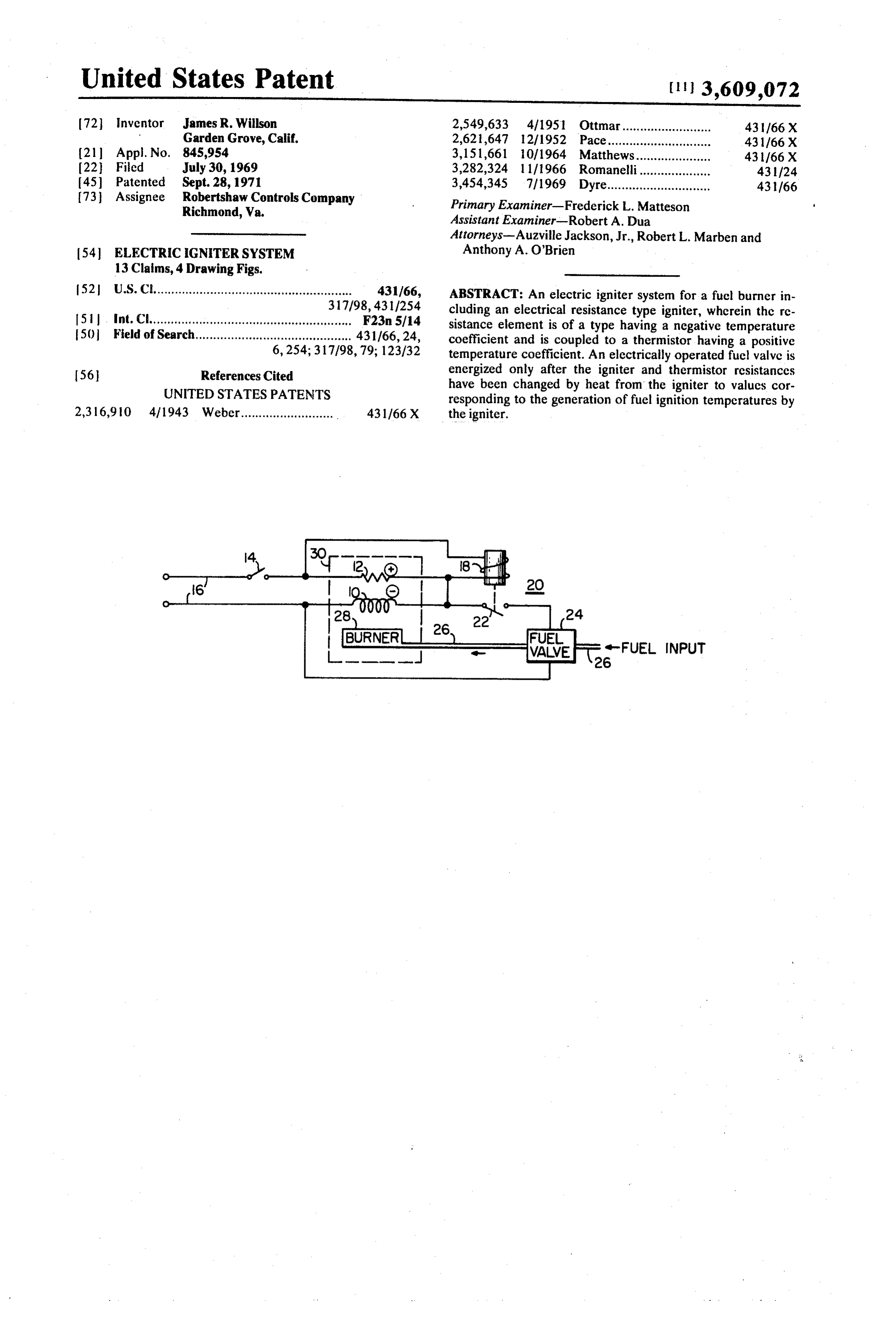
United States Patent (113,609,072 72) Inventor James R. Willson 2,549,633 4/1951 Ottmar......................... 431/66X Garden Grove, Calif. 2,621,647 12/1952 Pace..... 431/66 X 21 Appl. No. 845,954 3,151,661 10/1964. Matthews.... 431/66X 22 Filed July 30, 1969 3,282,324 1 1/1966 Romanelli... 431/24
73 Assignee Robertshaw Controls Company 3.454.345 ifi969 Dyre. 431/66
Richmond, Wa. Primary Examiner-Frederick L. Matteson
Assistant Examiner-Robert A. Dua
Attorneys-Auzville Jackson, Jr., Robert L. Marben and 54 ELECTRIC IGNITERSYSTEM Anthony A. O'Brien 13 Claims, 4 Drawing Figs.
52 U.S. Ct........................................................ 431/66, ABSTRACT: An electric igniter system for a fuclburner in 317/98,431/254 cluding an electrical resistance type igniter, wherein the re 51. Int. Cl....................................................... F23n 5/14 sistance element is of a type having a negative temperature 50 Field of Search............................................ 431/66, 24, coefficient and is coupled to a thermistor having a positive 6,254; 317/98, 79; 123/32 temperature coefficient. An electrically operated fuel valve is 56 References Cited energized only after the igniter and thermistor resistances UNITED STATES PATENTS have been changed by heat from the igniter to values cor responding to the generation of fuel ignition temperatures by 2,316,910 411943 Weber.......................... 431/66X the igniter.
Page 2
Drawing sheet — no readable text.
Page 3
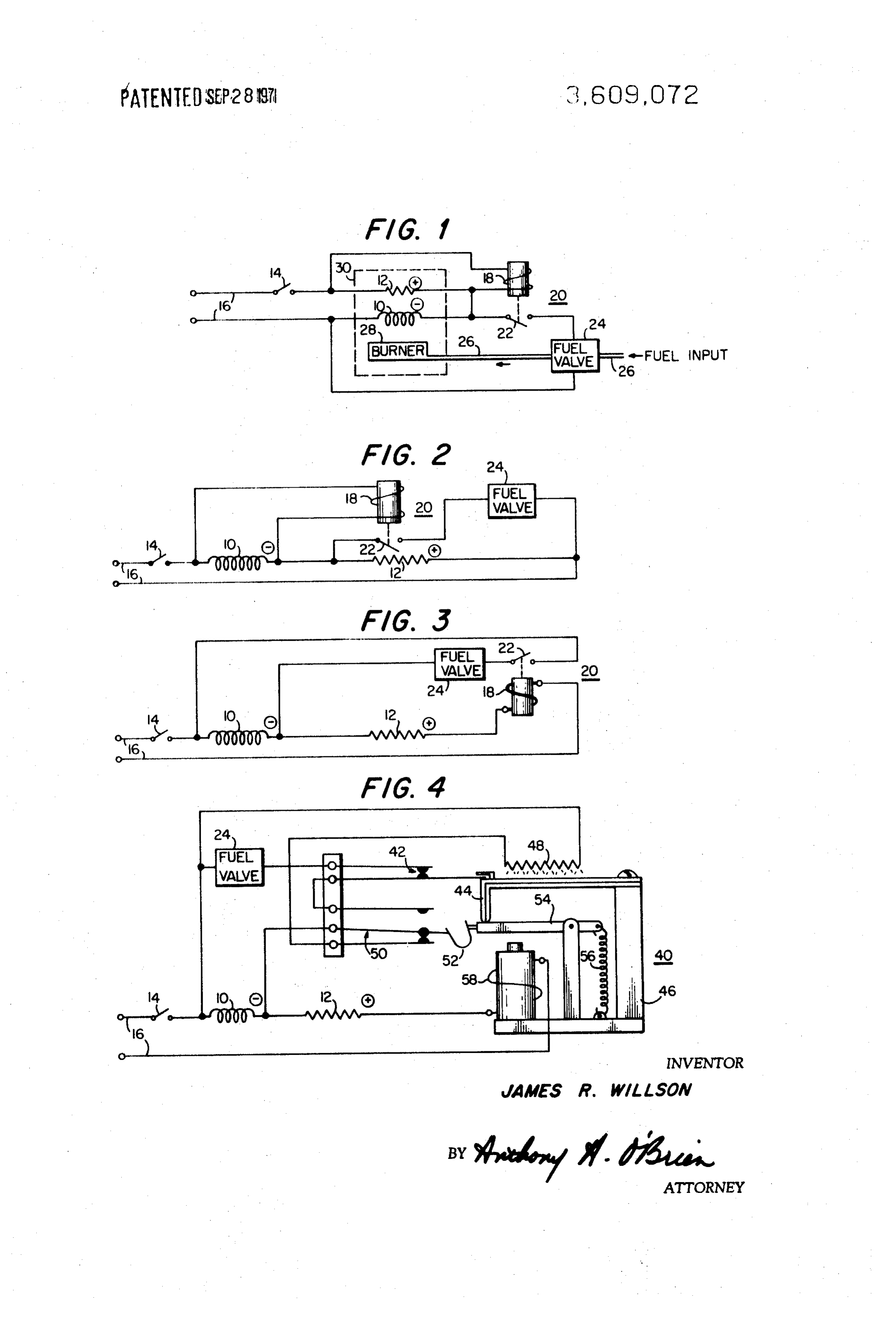
ELECTRCGNTERSYSTEM FIG. 2 is a schematic circuit diagram of a second embodi ment of an igniter system constructed according to the present
BACKGROUND OF THE INVENTION invention; - --
1. Field of the invention
FIG. 3 is a schematic circuit diagram of a third embodiment 5 of the present invention; and
The present invention relates to electric igniter systems for fuel burners and, more particularly, to an igniter system theFIG. 4 is a schematic circuit diagram of a modification of circuit illustrated in FIG, 3.
wherein an electric igniter element having a negative tempera ture coefficient of resistance is utilized in conjunction with a DESCRIPTION OF THE PREFERRED EMBODIMENTS thermistor having a positive temperature coefficient to pro 10 vide fail-safe operation. FIG. 1, which illustrates a preferred embodiment of the 2. Description of the Prior Art present invention, includes an electric igniter 10 having a Devices such as the bimetallic element have been employed negative temperature coefficient of resistance, connected in quite satisfactorily as heat sensors in systems employing pilot series with a positive temperature coefficient resistor 12 and a flame igniters to prevent raw fuel leakage into the area sur 15 switch 14. The entire series circuit is connected to a source of rounding the system burner upon pilot flame outage. How electrical power, illustrated for simplicity by lines 16. The ever, certain drawbacks soon become apparent; for example, energization winding 18 of an electromagnetic relay 20 is con pilot flame outage due to dust particle buildup was found to be nected in parallel with resistor 12 while the normally open common, and the slow switching time of the bimetallic sensors relay contacts 22, which are mechanically biased to an open often caused raw fuel leakage thereby creating a potentially 20 position (as illustrated) in the absence of electrical energiza dangerous condition. tion of the winding 18, are coupled in series with an electri Electric igniter systems have proven to be both reliable and cally operated fuel valve 24. The series circuit formed by efficient and have the ability to operate under the control of switch 22 and valve 24 is coupled in parallel with igniter 10 to rapid acting electrical safety circuits, thereby eliminating a complete the electrical circuit.
substantial hazard. In some instances, practical electric igniter 25 Fuel valve 24 is mechanically coupled in the fuel line 26 so elements having negative temperature coefficients of re as to control the flow of fuel from the fuel source to the burner sistance have been utilized for ignition and control of fuel 28 that is suitably supported in conventional burner apparatus flow. While such igniter systems have particular advantages in 30. The igniter 10 is located within igniting proximity of the their respective arrangements, it is desirable to develop igniter burner 28 while resistor 12 is adapted to be positioned ad systems having increased safety, simplicity of operation and 30 jacent the igniter so that the temperatures of the igniter and economy of manufacture. the resistor are maintained approximately equal. It is noted SUMMARY OF THE INVENTION that while the physical location of igniter 10, resistor 12 and burner 28, with respect to each other, is the same for all em
It is, therefore, an object of the present invention to con bodiments of the present invention, it has been schematically struct an electric ignition system having all the advantages of 35 illustrated only in FIG. 1 for the sake of simplicity and clarity, similarly employed prior art systems but utilizing fewer com it being understood that a similar placement of the elements in ponents than the components essential to such systems. all the figures is intended.
Another object of this invention is to provide an electric ig Referring now to FIG. 2, igniter 10 is connected in series niter system employing an igniter element having a negative with resistor 12 and switch 14 across power source 16, as in temperature coefficient of resistance as both an igniting 40 FIG. 1. However, in this embodiment relay energization wind means and a heat sensing means. ing 18 is connected in parallel with igniter 10 while fuel valve This invention has a further object in the provision of an 24 is connected in parallel with resistor 12 via relay contacts electric ignition system having fail-safe characteristics assur 22.
ing fuel ignition. In FIG. 3, the same basic circuit is shown as in F.G. 1 with An additional object of the present invention is the provi 45 the exception that the relay energization winding is connected sion of an electric ignition system having raw fuel leakage in series with the thermistor 12 and is constructed so as to be prevention characteristics in the event of either an open cir current sensitive rather than being voltage sensitive as in the cuitor a short circuit in the igniter element. preceding two figures.
An advantage of the invention is the provision of a simple FIG. 4 is a modification of the circuit of FIG. 3 with the sub and reliable electric igniter system having few parts and in 50 stitution of a bimetal actuated switching device 40 for relay herent safety characteristics.
The present invention is summarized in that an electric igni 20. Device 40 includes a switch 42 which is directly controlled by the movement of a bimetallic arm 44 mounted upon a tion system for a fuel burner includes an electrical power frame 46. Bimetallic arm 44 is illustrated in its cold position source coupled to an electric igniter having a negative tem wherein switch 42 is maintained closed. The arm 44 is heated perature coefficient of resistance which is adapted to be 55 by a heating element 48 which is connected in parallel with ig located within igniting proximity of the burner. The system further includes a resistor adapted to be heated by the igniter niter 10 through one side of a single pole double throw switch and having a positive temperature coefficient, and an electri 50. Switch 50 is controlled through a snap-action spring 52 by cally operated valve adapted to control a flow of fuel to the 60 lever biased arm 54 which is pivotally mounted upon frame 46 and is by spring 56 against the free end of bimetallic arm 44.
burner. The igniter, resistor and valve are coupled to a circuit which is responsive to the resistance of the igniter and the re Thus, in the position shown, switch 50 provides a closed path sistor for enabling energization of the valve, to thereby from the igniter to the heater element 48 through the lower contacts, as shown. The upper contacts of switch 50 complete establish a flow of fuel, only when the igniter is above fuelig the parallel niting temperatures and for disabling the valve when the ig energization.connection The device of fuel valve 24 to the igniter 10 for 40 also includes a holding coil 58
niter develops either an electrical short circuit or an electrical which functions to hold lever arm 54 after it has becn moved open circuit.
These and other objects and advantages of the present in downward by bimetallic arm 44 but is incapable of generating vention will become more fully apparent from the following atuated sufficient magnetic field to pull lever 54 down from its unac position, as illustrated.
detailed description of the preferred embodiments of the in 70 In explaining the operation of the circuits described above, vention when considered in conjunction with the accompany a typical installation of the igniter circuit in a central heating ing drawing. furnace system will be used. In such a system, switch 14 would BRIEF DESCRIPTION OF THE DRAWINGS function in a conventional manner either as a main power switch, a thermostatically operated ambient temperature
FIG. 1 is a schematic circuit diagram of an electric igniter 75 sensing device, or a combination power thermostat switch. It system embodying the present invention;
Page 4
should also be noted that the placement of switch 14 in the cir drop out and remove the fuel valve from its electrical power cuit is not critical to the invention and may be modified in ac SOC.
cordance with the particular operational characteristics In the circuit shown in FIG. 3, the igniter 10 is connected in desired for various different installations. series with thermistor 12 and relay winding 18 across the Referring to FIG. 1, when the circuit is inactive switches 14 power source 16 through switch 14. The relay winding 18 is of and 22 will be open, as shown. Since no power will therefore a low-impedance type and, as such, is current sensitive and be applied, the temperature of both the igniter 10 and the will be energized to close contacts 22 only when the resistance thermistor 12 will be low; and, due to the negative and positive of igniter 10 has decreased to the point where sufficient cur temperature coefficients of resistance of the igniter and O rent is drawn by the combination. The relay, thermistor and thermistor, respectively, the initial resistance of the igniter will igniter after are designed to provide the requisite current flow only the igniter has reached fuel igniting temperatures to be high in comparison with that of the thermistor.
When a demand for heat arises, switch 14 will become thereby prevent raw fuel leakage. It is noted that in this em closed to thereby feed power from the source 16 to the series bodiment the rate of change of resistance is greater for the ig combination of thermistor 12 and igniter 10. By visualizing 15 niter than for the thermistor so that the net rate of change of this series circuit as a resistive voltage divider, the initial volt current flowing therethrough increases as the temperature of age drop across the igniter 10 can be seen to be high with the igniter increases, the thermistor functioning to limit the respect to the thermistor 12 in direct relation to the initial current through the circuit to prevent thermal runaway by the value of their respective resistances. At this same time, the ig igniter.
niter begins to increase in temperature which causes the volt 20 current In the event that the igniter becomes an open circuit, the age drop of the igniter to decrease and that of the thermistor flow through the relay winding will cease and fuel flow to increase as their resistances vary. Thus, the voltages ap will be blocked by the fuel valve 24. Similarly, if the igniter pearing across the two major heat sensing components, name becomes a short circuit, the energization voltage across the ly thermistor 12 and igniter 10, vary in opposite directions in fuel valve will become zero, thereby causing immediate clo proportion to the temperature of the igniter 10. 25 sure thereof.
In the circuit of FIG. 1, the voltage drop across the Referring now to FIG.4, when switch 14 is initially closed, thermistor is applied to relay energization winding 18, while current will flow through the igniter 10, the thermistor 12 and the drop across the igniter is fed to the fuel valve 24 via the the holding coil 58. The initial voltage drop is primarily across relay contacts22. Therefore, prior to igniter heat-up the small the igniter since thermistor 12 has an initial low resistance and holding coil 58 is selected to be of a low impedance current voltage across the thermistor 12 will be insufficient to energize 30 sensing the relay and the large voltage drop across the igniter will be type. The large potential drop across the igniter is fed prevented from actuating the fuel valve by the open switch to heater element 48 through the lower set of contacts of contacts 22. In this embodiment, the relay 20 is voltage sensi switch 50 whereupon the heat generated thereby causes tive and will close contacts 22 only after the resistance of the 35 bimetallic arm 44 to deflect away from the heater 48. This thermistor, and therefore its voltage drop has been increased causes switch 42 to open and then, by movement of lever arm by the heating of the igniter to fuel igniting temperatures. As a 54, causes switch 50 to snap to its upper position whereupon result, initial fuel flow is prevented until sufficient igniter tem the heater element 48 is removed from the circuit. During this perature has been attained, thus assuring immediate ignition series of events the igniter 10 becomes hot thereby changing whenever fuel if fed to the burner. its resistance to permit a larger flow of current through the Considering now the operation of the circuit after burner ig 40 holding coil 58. The coil then produces sufficient magnetiza nition has been established, it is noted that the igniter 10 is tion to maintain lever arm 54 in its deflected position, thereby coupled in series with the parallel combination of thermistor maintaining the upper contacts of switch 50 closed, while 12 and energization winding 18, and is coupled in parallel with bimetallic arm 44 begins to return to its cold or rest position. the series combination of fuel valve 24 and relay contacts 22. 45 The bimetal, as it continues to return to rest, then closes Therefore, if the igniter developes an open circuit, the flow of switch 42 to complete the parallel connection of the fuel valve current through the thermistor-relay parallel circuit will cease with the igniter through switch 42 and the upper contacts of causing immediate drop out of contacts 22 to thereby stop the switch 50. The system is designed so that the aforedescribed flow of fuel. In the event of a short circuit in the igniter, the series of events will occur in no shorter time than the time voltage across the fuel valve 24 will drop to zero causing its 50 required for igniter 10 to come up to fuel ignition tempera immediate closure. Thus, both open and short circuit protec tures. This safety factor is further increased by the fact that tion is provided to assure fail-safe operation at all times. only after the resistance of igniter 10 has been decreased by The circuit of FIG. 2 operates in similar manner as that of the generation thereby of fuel ignition temperatures will suffi FIG. 1. In this Figure, however, the relay winding is connected cient current flow through the holding coil 58 to maintain in parallel with the igniter while the fuel valve is connected 55 lever arm 54 and, therefore, switch 50 in their actuated posi across the thermistor through the relay switch 22. In opera tions, tion, the initial large voltage drop across the igniter upon clo After ignition, if the igniter in the circuit of FIG. 4 develops sure of switch 14 in response to a demand for heat energizes a short circuit, the voltage across the fuel valve will become zero thereby cutting off the flow of fuel to the burner.
relay 20 to place the fuel valve directly across thermistor 12. Similarly,
However, the fuel valve in this embodiment is voltage sensitive 60 the voltage to the fuel valve will be removed by the and will not function to establish a flow of fuel to the burner switch 50 if the igniter develops an open circuit since the cur until the resistance of the thermistor, and therefore, its voltage rent flow through the holding coil will cease and lever arm 54 drop has been increased by the heating of the igniter to fuelig will be released.
niting temperatures. Therefore, raw fuel leakage is prevented Therefore, there is provided in all of the illustrated embodi during periods of normal operation. 65 ments an electric igniter system which is permitted to cycle As in the circuit of FIG. 1, igniter short circuit and open cir continuously in response to a demand for heat while providing cuit protection is provided by the system of FIG. 2. More raw fuel leakage prevention as well as igniter short or open cir specifically, the serics connection of the fuel valve and the ig cuit fail-safe operation.
niter is designed to block the flow of current to the fuel valve 70 tions,In as much as the present invention is subject to many varia if, for any reason, the igniter becomes an open circuit. This in all matter modifications and changes in detail, it is intended that herently causes the fuel valve to shut off the fuel flow to the the accompanying contained in the foregoing description or shown in system burner to prevent raw fuel from collecting. A short cir drawing shall be interpreted as illustrative cuit in the ignition element will also produce immediate fuel andWhat not in a limiting sense.
cutoff since the short circuit will remove the energization volt 75 1. An iselectric claimed is:
ignition system for a fuel burner comprising age from the relay winding 18 causing the relay contacts 22 to
Page 5
input means adapted to be connected with an electrical voltage drop thereacross, power source, an electrically operated valve adapted to control a flow of an electric ignitor coupled to said input means and adapted fuel to the burner and being electrically coupled with said to be located within igniting proximity of the burner, electric ignitor and said input means for energization by said igniter having a negative temperature coefficient of re said power source when said ignitor is above fuel ignition sistance, temperature, - a resistor having a positive temperature coefficient of re switch means connecting said electrically operated valve sistance coupled in series with said igniter and adapted to with said ignitor whereby said valve is deenergized to be heated thereby, thereby inhibit fuel flow therethrough whenever said igni an electrically operated valve adapted to control a flow of 10 tor develops an electrical short circuit, and fuel to the burner, and circuit means connected with said ignitor and said switch means coupled to said ignitor, said resistor, and said valve means for disabling said valve to thereby inhibit fuel flow and responsive to the relative resistances of said ignitor therethrough when said ignitor develops an electrical and said resistor for enabling energization of said valve to open circuit.
establish a flow of fuel when said ignitor is above fuel ig 15 9. The invention as recited in claim 8 wherein said switch niting temperatures and for disabling said valve upon means connects said electrically operated valve across said ig failure of said ignitor. niter and wherein said circuit means is connected in series cir 2. The invention as recited in claim 1 wherein said means in cuit with saidtoignitor, said switch means and said circuit means cludes an electric relay having an energization winding and a cooperating inhibit actuation of said valve until said ignitor switch responsive thereto, said switch being coupled in series 20 reaches fuel ignition temperatures. 10. The invention as recited in claim 9 wherein said circuit with said valve to form a series circuit.
3. The invention as recited in claim 2 wherein said series cir means comprises a resistor having a positive temperature cuit is coupled in parallel with said resistor, and said energiza coefficient of resistance and an energization winding of an electric relay coupled to form an electrical parallel circuit, tion winding is coupled in parallel with said ignitor.
4. The invention as recited in claim 2 wherein said series cir 25 and wherein said switch means comprises a normally open switch adapted to be closed in response to energization of said cuit is coupled in parallel with said igniter and said energiza winding, tion winding is coupled in parallel with said resistor. said switch being coupled in series with said electri 5. The invention as recited in claim 2 wherein said series cir cally operated valve.
cuit is coupled in parallel with said igniter and said energiza means 11. The invention as recited in claim 9 wherein said circuit comprises a resistor having a positive temperature tion winding is coupled in series with said resistor and said ig 30 coefficient nitor. of resistance and an energization winding of an 6. The invention as recited in claim 5 further including ther electric relay coupled to form a series circuit, and wherein mally responsive switch means connected with said valve and said switch means comprises a normally open switch adapted said relay, said thermally responsive switch means including a to be closed upon energization of said winding, said switch bimetallic element and an electric heater located within heat 35 being coupled in series with said electrically operated valve. 12 The invention as recited in claim 11 wherein said ener ing proximity of said bimetallic element and coupled with said gization winding is a holding coil, and wherein said switch ignitor. means further includes thermally responsive switching means 7. The invention as recited in claim 6 wherein said thermally connected with said electrically operated valve and said nor responsive switch means further includes a normally closed 40 mally open switch, switch coupled in series with said valve and said relay switch cluding a bimetallicsaidelement thermally responsive switch means in and an electric heater located and adapted to be opened by said bimetallic element in within heating proximity of said bimetallic element and cou response to energization of said electric heater, and wherein said relay further includes a normally closed switch connected pled13.with said ignitor.
The invention as recited in claim 12 wherein said ther in series with said electric heater, said relay being initially ac tuated by said bimetallic element and being maintained in its closedresponsive 45 mally switching means further includes a normally actuated position by said energization winding whenever said valve and said normallyinopen switch coupled series with said electrically operated switch and adapted to be opened ignitor is above fuel igniting temperature. by said bimetallic element in response to energization of said 8. In an electric ignition system for a fuel burner, the com electric heater, and wherein said relay further includes a nor bination comprising input means adapted to be connected to an electrical power 50 mally closed switch connected in series with said electric heater, said relay being initially actuated by said bimetallic
Source, element and being maintained in its actuated position by said an electric ignitor adapted to be located adjacent the burner holding coil whenever said ignitor is above fuel igniting tem and coupled to said input means, said ignitor having a negative temperature coefficient of re 55 peratures.
sistance thereby producing a temperature dependent
Provenance
- Collection
- Cited prior art
- Original PDF
- patentimages.storage.googleapis.com →
- Filed
- 1969-07-30
- Pages
- 5
- Method
- pdftotext (the PDF's own text layer) + pdftoppm 300dpi page scans
- Source
- Google Patents bibliographic record
- Granted
- 1971-09-28
- Inventors
- James R Willson; Robertshaw Controls Co
- Transcribed from
- patentimages.storage.googleapis.com →