patent · US2688360
Fuel combustion system, including gas assisted atomizer
7 September 1954
Page 1
Sept. 7, 1954 G. P. HAYNES ET AL 2,688,360
FUEL COABUSTION SYSTEM, INCLUDING GAS ASSISTED ATOMIZER
Filed April 13, 195l. 3 Sheets-Sheet l //ast SelaaZY
Capaap 1/M /M/ZaZS
Nkrks wer
essa
Sperators
aayaaa. 4a Ya-YA/
Page 2
Sept. 7, 1954 G. P. HAYNEs ET AL 2,688,360
FUEL COMBUSTION SYSTEM, INCLUDING GAS ASSISTED ATOMIZER
Filed April 13, 1951 3 Sheets-Sheet 2
uuouseumuunununu
OHRC uuunromaruvuu ass
seizealizatians
SNSEEN (
INVENTORS
JaMyzaz Zafiz A1//
Page 3
Sept. 7, 1954 G. P. HAYNES E TAL 2,688,360
FUEL COMBUSTION SYSTEM, INCLUDING GAS ASSISTED ATOMIZER
Filed April 13, 195l -. 3. Sheets-Sheet 3
swSS
VaVaYaNY YAYAvy 2 assa SSNSSasasana Sea
Yay
SiSS
74 yas
SaM12/az Aaz A///
Page 4
Patented Sept. 7, 1954
UNITED STATES PATENT OFFICE
FUEL COMBUSTION SYSTEM, INCLUDING
GAS ASSISTED ATOMZER
George P. Haynes, Hempstead, and Samuel Letwin,
Elmhurst, N. Y., assignors to Thermo Projects
Incorporated, a corporation of New York
Application April 13, 1951, Serial No. 220,860
This invention relates to fuel combustion sys connection with a fog generator, whereas the tems for burning liquid fuels and particularly Specific form of atomizer illustrated in the pres to gas assisted atomizers for use therein. ent case is applied to fuel combustion. In the combustion of fuel oils, particularly The general objects of the invention are to the heavy oils, effective atomization of the oil is provide a fuel combustion system in which Some of prime importance, as Such atomization is ne or all of the advantages described are realized. ceSSary to produce complete burning of the fuel, Specific objects and advantages of the invention and also insure the minimum formation of car Wall appear in connection with the description bon deposits and slags in the furnace. It is also of one preferred embodiment thereof illustrative important to provide an atomizer System which O of the principles of the invention which will be will operate satisfactorily throughout a large described in detail in connection with the ac range of combustion rates. companying drawings forming a part of this In accordance with the present invention an Specification.
atomizer is provided in which hot combustion In the drawings:
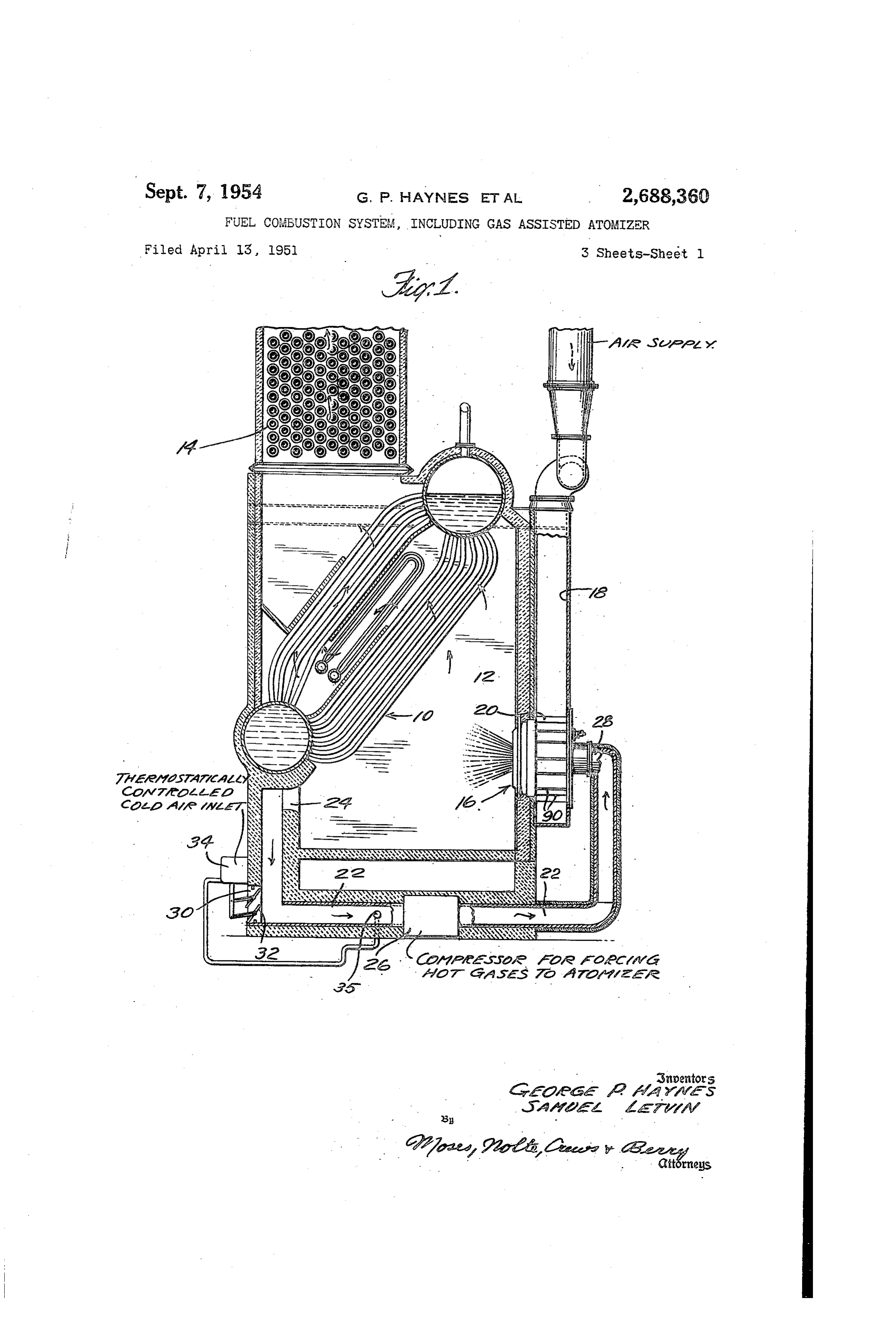
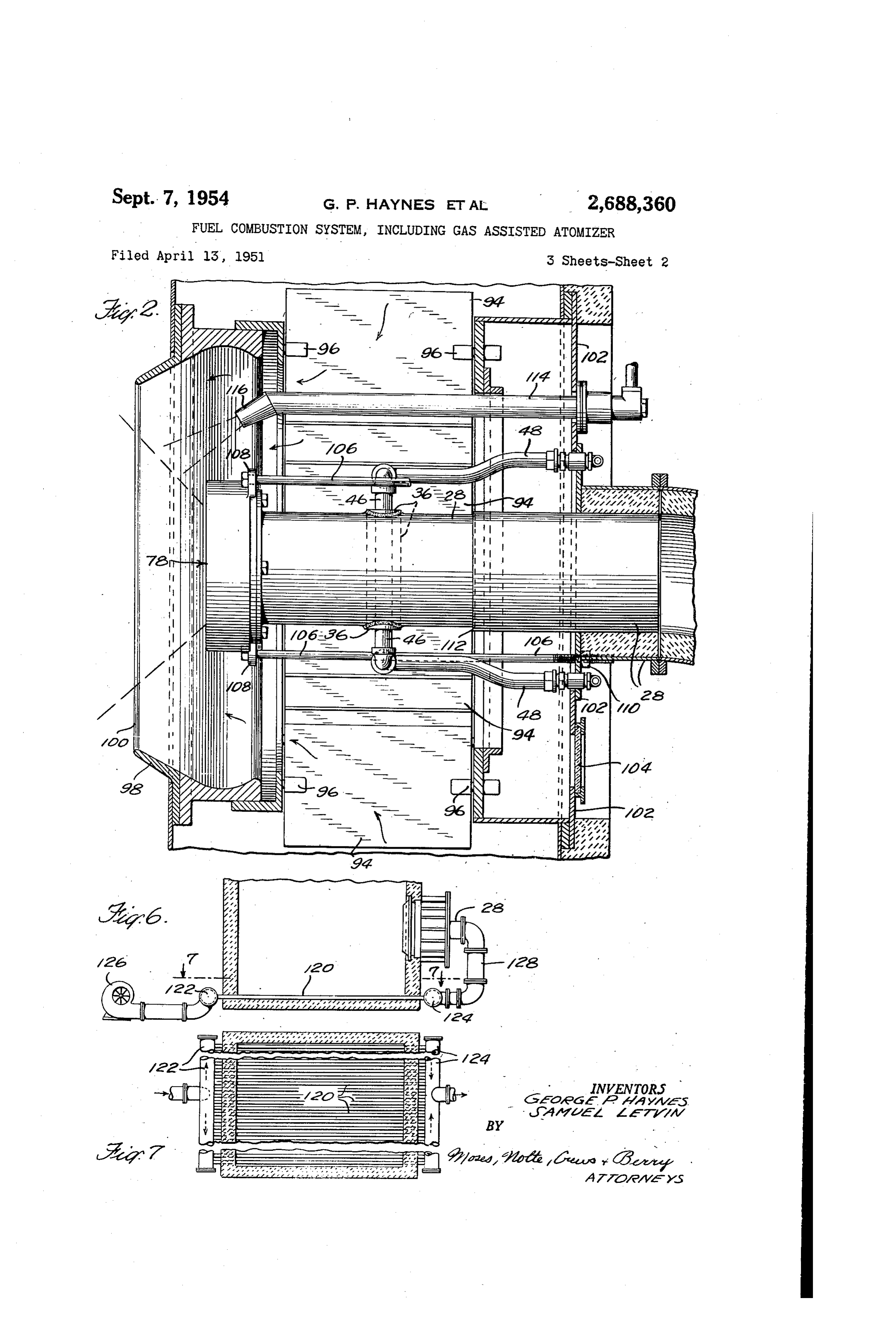
gases or heated air are introduced in such a way 15 Figure 1, is a diagrammatic view in vertical as to effect a very complete atomization before section showing a boiler and furnace with one the Secondary air supply is mixed with the fuel. form of the improved atomizer applied thereto; Such assisting gas may conveniently be provided Figure 2 is a Wertical Sectional view of the air by utilizing a part of the products of the com- register, the atomizer being shown in elevation; bustion from the furnace, which are recirculated 20 a larger to the atomizer. The System of the present in-
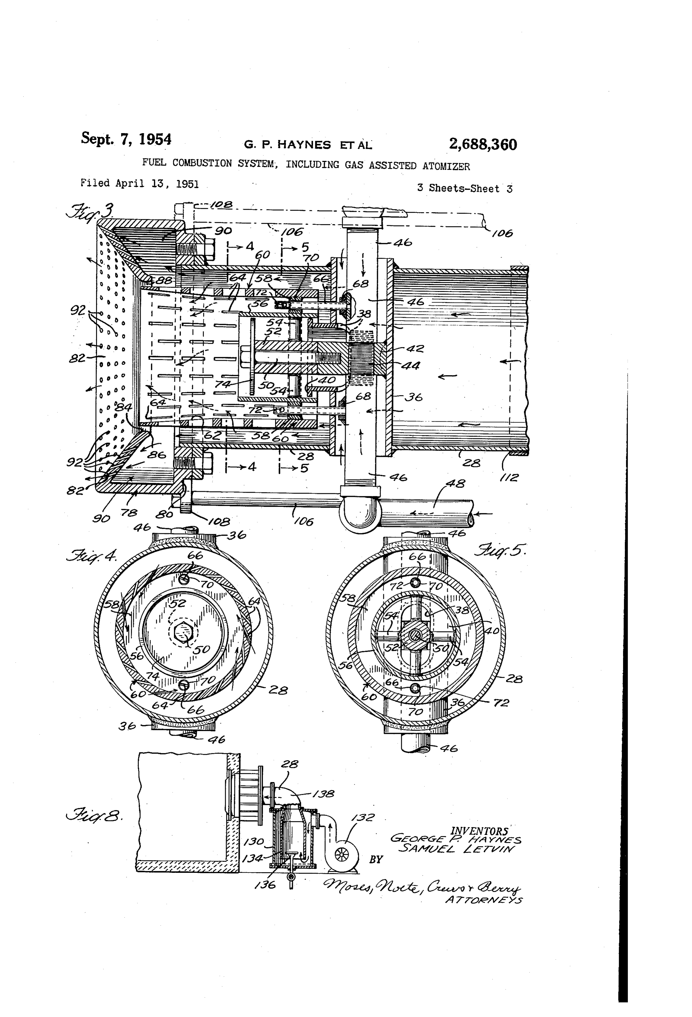
Figure scale 3 is a than vertical section of the atomizer on
Vention is effective within a substantial variation Figure 4 is a transverse section on line 4-4 of temperature ranges, does not require excessive of Fig. 3;
fuel oil pressures, and provides a system which Figure 5 is a similar section on line 5-5 of may be operated With simplified automatic con- 25 Fig. 3;
trols. Also the oil feed passages of the burner Figure 6 is a fragmentary diagrammatic view are of relatively large size so that danger of in Wertical Section showing the lower part of a clogging is minimized. Control means for the boiler furnace with the air register thereon and introduction of the Secondary air supply may also illustrating a modified arrangement for heating be simplified and draft losses through the air 30 primary air for an atomizer in the register; regulator minimized. Temperatures of the fuel Figure 7 is a horizontal sectional view on line oil as Supplied to the burner can also be lowered. 7- of Fig. 6; and
For example instead of preheating the oil to Figure 8 is a fragmentary diagrammatic view the temperatures commonly necessary at present in vertical section showing part of the furnace of from 130 to 150 F., the oil may be supplied 35 and air register With another means for supply attemperatures of from 70° to 100° F., in some ing heated primary air.
Cases even less. Referring to the drawings in detail, Fig. 1 The present invention also provides a fuel illustrates one embodiment of the invention as Combustion System by which the fuel can be com applied to a boiler furnace. A conventional pletely and cleanly burned with practically zero 40 Water tube boiler is shown at f 0 mounted in a excess air. For Some uses, this is very important, Combustion chamber 2. The products of com not only as promoting efficiency in the use of the bustion pass out through an economizer A to a fuel, but also for producing a substantially non Stack. The register and atomizer structure as a Oxidizing atmosphere in the furnace. For the Whole is indicated by numeral 6. The secondary latter reason the System is applicable to various 45 air is Supplied through a duct 8 to the air reg metallurgical processes such as for heating bil ister 20 to which the air is forced under low lets for steel process work and also as applied preSSure by a Suitable blower. In the particular to Open hearth furnaces and under other con example shown heated gases are supplied to the ditions where a non-oxidizing atmosphere is de atomizer through a duct 22 which connects With Sirable. 50 a port 24 in the combustion chamber wall. In the
The particular atomizer construction shown duct is a compressor 26 which draws the hot herein is an improvement upon or development gases from the combustion chamber through the of the form of atomizer shown in our application, port 24 and compresses the gases to the desired Serial No. 689,158, filed August 8, 1946 now Patent preSSure and forces them into the atomizer cas
of that application is illustrated specifically in In order to reduce and regulate the tempera
Page 5
ture of the gases so as to maintain the tempera outside of the cup 60 and the casing 28, part of ture within the desired limits, cold air is admitted the air and gases entering the cup through the into the duct 22 through an inlet port 3G which is . slots 64. Some of the low pressure air from the controlled by adjustable louver blades 32. These interior of the air register will pass through the are preferably automatically controlled by a 5 tubes 36 and 38, sleeve 56 and the space around thermostatic control device 34, the temperature the baffle 74 into the interior of the cup. Thus it responsive element 35 of which is located at a will prevent the formation of a vacuum in the Suitabie point such as in the duct 22 beyond the center of the cup due to Vortex action. port 3G. A very close regulation of the tempera On the end of the casing 28 Surrounding the ture has not been found necessary. The tem 10 mouth of the atomizing cup is a hollow diffuser peratures used will depend to Some extent upon ring 78. This is provided with a lear wall 80 the nature of the fuel being burned. With the attached to a flange at the end of the casing, and heavy grades of oil usually employed tempera with an outer flaring or inclined Wall 82. This tures between 800 F. and 1300 F, have been Outer or front wall 82 has a central opening 84 found satisfactory. 5 and preferably terminates in a curved flanged The atomizer casing 28 is mounted in the air portion 88 forming the margin of the opening. register structure and comprises a tube extending The opening 84 is somewhat larger than the outer centrally across said structure. Extending trans diameter of the cup 60 so as to provide an annu Versely across the central part of the casing 28 lar space 88, through Which a part of the gases is a supporting tube 36. Mounted in an opening 20 issues. A major portion of the gases from the in the side of the tube is a partly flattened pipe space around the cup 60 passes into the hollow Section 38 which terminates at its outer end in a chamber 90 of the diffuser ring, and issues circular flange (FigS. 3 and 5). Mounted on through a multiplicity of Oujtwardly inclined holes the back of the tube 36 and projecting outwardly 92 in the flaring wall 82 of the diffuser. The gases into the pipe Section 38 is a block 42 having a 25 issuing through these holes. 92 and through the threaded transverse bore therein in which is a space 88 draw out the finely atomized fuel issuing Screw-threaded plug or nipple member 44 from the mouth of the cup so as to induce intimate the ends of which project outwardly as shown in intermixture between the secondary air from the dotted lines in Fig. 3. Screwed on these threaded register and the atomized fuel. A short, wide ends are two oil pipe Supply sections 46 which 30 flame is thus produced which is most effective for are connected to supply pipes 48 coming from a use in a furnace of the general type illustrated. Suitable Source of oil under pressure (not shown). By proper design of the diffuser and associated Mounted on a stud bolt 50 Screwing into the end parts the character and shape of the flame may of the block 42 is a sleeve 52 which has arms 54 be adapted to suit particular conditions of use. projecting radially therefron which carry a sleeve With the construction of atomizer described, 56. The end of the sleeve encloses the flange 40, no oil passages of very fine gage are required. a sufficient clearance being allowed to permit Therefore problems connected with the straining expansion and contraction. Mounted on the or filtering of the oil are simplified and danger of sleeve 56, preferably about opposite the ends of clogging is minimized. Very high oil pressures arms 58, is a ring 58 which carries an atomizer 40 are not required, pressures, on the order of 100 cup 60, the outer part of the inner surface of p.s. i. being ordinarily sufficient, as distinguished which may flare outwardly slightly as indicated from many atomizers which require pressures up at 62. The wall of the cup 69 is provided with to as much as 1000 p.s. i.
a multiplicity of perforations or slots 64 which The pressure of the assisting gases as produced are preferably elongated in the direction of the by the compreSSOr. 26. may be varied within con axis of the cup and arranged in Staggered roWS. siderable limits, a desirable pressure with a These slots 34 are inclined in a generally tangen 'burner of the proportions. shown being in the tial direction as indicated in Fig. 4, so as to pro neighborhood of 100 p...S. i. The main or Second duce rapid rotation of gases entering the cup ary air supply which is at a very much lower through these slots. Oil is Supplied to the attorn 50 pressure, perhaps 2 or 3 p.S. i., enters through izer through axially extending pipes 66 screwing the air register and 'is' controlled in any suitable into bosses 68 on the side of pipes 46. The pipes manner, as by the dampers, 94 pivotally mounted 66 extend through holes. 0 in the ring 58 and are at points 96 and controlled in any suitable man closed at their outer ends. Each of the pipes ner (not shown). With the atomizer construc has a transverse opening 72 into the bore in the 55 tion of the present invention it has been found pipe near its outer end. The openings 2 in the that a close control of the damperS is not neces respective pipes face in tangential directions so sary, and in fact, adjustable damper blades may that oil issuing from the holes 72 will be projected in Some instances be dispensed. With. tangentially and will start the oil rotating in the The air entering between the damper blades same direction as the direction of rotation which 60 passes into the venturi, 93, which may be of usual will be given to the oil by the gases entering the construction, and mixes with the combustible cup through the slots 64. Oil is thus supplied to gases passing into the furnace through the Wen turi orifice. 09. The general construction of the the atomizer cup and rotates rapidly therein as register it mixes with the gases and passes out through may be conventional. It is shown as pro the open end or mouth of the Cup. 65 vided With an outer Wall: 02 in which is a sight Mounted at the end of the sleeve'52 on the bolt glass 04. Supporting rods 406 are preferably 56 and near the Outer end of the sleeve 56 is a provided connected to lugs 8 on the diffuser baffle disc 74. The periphery of this is spaced ring. These rods -06 pass through holes in the from the inside of sleeve 56 SO as to leave a nar'- wall 02 and are engaged by adjusting nuts ff0. row passageway around the disc. The baffle 74 70 By adjusting these nuts.the position in the ven is useful in preventing flanes from extending into turi of the mouth of the atomizer cup and of the the sleeve 56. diffuser ring may be varied. The casing 28. is The relatively high pressure hot air and gases provided with a telescopic portion f2 to permit from the duct 22 pass through the casing 28 . such adjustment to be made.
around the supporting tube, 36 and between the 75 The register is preferably provided with a suit
Page 6
able lighting off device, such as the retractable with the combustion chamber and leading to the ignition tube 4 provided with a flame jet f 6. atomizer, means for raising the pressure of gases This jet may be lighted in any suitable way a Withdrawn from the combustion chamber and by an electric igniter (not shown). forced through said duct to the atomizer, and The gas assisted System described by which valve means for admitting a regulated amount heated gases under pressure are used for assist of cooler air into Said duct. ing in the atomization of liquid fuel may be used 2. A combustion System including a combustion with various specific forms of atomizers designed chamber, air register means including a venturi to utilize Such heated gases. Various modifica tions in the method of providing the hot gases 0 opening into said chamber, means for Supplying secondary air to said air register means, a fuel
Or air under preSSure may also be utilized in con atomizer discharging into said venturi, Said fuel nection with the form of atomizer shown. The atomizer including a duct for hot gases Opening hot gases may produce Some vaporization of the into the venturi and an atomizing cup mounted lighter ends of the liquid fuel, but the action is in the discharge end of Said duct, Said cup being primarily a mechanical atomization. The heavy 15 smaller in diameter than the discharge end of oils commonly used in a burner of this type do the duct, so as to leave a gas discharge Space not readily vaporize, and the amount of heat used around the cup, said cup having tangentially in is insufficient to produce anything like complete clined orifices in the wall thereof for admitting vaporization or gasification prior to the actual hot gases from said duct to the interior of Said flame formation in a combustion chamber. 20 cup, said cup having a mouth opening into the Two constructions for providing heated pri venturi adjacent to the end of the duct, and mary air for assisting in the atomization of the means for discharging liquid fuel under pressure fuel are shown by Way of illustration as alter into said atomizing Cup.
natives of the construction shown in Fig. 1. One 3. A combustion system including a combus such construction is shown in Figs. 6 and 7. In 25 tion chamber, air register means including a stead of the auxiliary air and hot gas Supply venturi opening into Said chamber, means for being withdrawn directly from the furnace a supplying secondary air to said air register means, series of heat, exchanging tubes 2 are mounted a fuel atomizer discharging into Said venturi, Said in the furnace which are connected at their ends to manifolds 22 and 24. Air is forced 30 fuel atomizer including a duct for hot gases opening into the venturi and an atomizing cup into the manifold 22 by blower 26, paSSes mounted in the discharge end of Said duct, Said through the heated tubes E20 and is carried from cup being smaller in diameter than the discharge the manifold 24 through pipe 28 to the atomizer end of the duct, so as to leave a gas discharge casing 28. This construction will provide pure space around the cup, said cup having Substan heated air as distinguished from air mixed with tially tangential orifices in the Wall thereof for hot products of combustion which are furnished admitting hot gases from said duct to the in to the atomizer by an arrangement Such as shown terior of said cup, said cup having a mouth Open in Fig. 1. ing into the venturi adjacent to the end of the In Figure 8 another possible construction is duct, and means for discharging liquid fuel under illustrated for supplying assisting gases to the 40 pressure into said atomizing cup, Said last named atomizer. In this construction a stove 30 is means having orifices for discharging fuel into provided through which air is forced by a blower the cup near the inner surface thereof. 32. In the stove construction illustrated the air passes downwardly through the Outer casing tion chamber, air system 4. A combustion including a combus register means including a of the stove and around the bottom edge of the venturi opening into said chamber, means for combustion chamber 34. In the interior of the supplying secondary air to Said air register means, latter a small oil burner 36 is mounted which a fuel atomizer discharging into Said venturi, heats the air as the oil burns with a part of the said fuel atomizer including a duct for hot gases air, so that hot air and gases pass out of the opening into the venturi and an atomizing cup outlet 33 from the stove to the casing 28 of the 50 mounted in the discharge end of Said duct, Said atomizer. With this construction a considerable cup having substantially tangential Orifices in excess of air over that consumed by the burner the Wall thereof for admitting hot gases from 36 Will be heated.
While certain preferred embodiments of the said duct to the interior of said cup, said cup invention have been illustrated and described in having a mouth opening into the Venturi adjacent to the end of the duct, means for discharging detail, it is to be understood that changes may liquid fuel under pressure into Said atomizing be made therein and the invention embodied in cup, and a flame guard disc mounted trans other structures. It is not, therefore, the inten tion to limit the patent to the Specific Construc versely of the axis of the cup so as to leave an annular space for the exit of air around the tions illustrated, but to cover the invention. 60 periphery of Said disc.
broadly in whatever form its principles may be 5. A combustion System including a combustion utilized. chamber, air register means including a Venturi We clain: opening into said chamber, means for Supplying 1. A fuel . . combustion System comprising a secondary air to said air register means, a fuel combustion chamber, a register having a venturi atomizer discharging into said venturi, Said fuel opening into the combustion chamber, means for atomizer including a duct for hot gases opening supplying secondary air to said register, a fuel into the venturi and an atomizing cup mounted atomizer in said register, said atomizer including in the discharge end of Said duct, Said cup having an atomizer cup having a mouth Opening into substantially tangential orifices in the Wall there the venturi out of contact with the Surrounding 70 of for admitting hot gases from said duct to wall thereof, means for Supplying fuel to the the interior of said cup, said cup having a interior of the atomizer cup, and means for Sup mouth opening into the venturi adjacent to the plying hot gases under pressure to said atomizer end of the duct, means for discharging liquid to assist in the atomization of the fuel, said last 75, fuel under pressure into said atomizing cup, a named means including a duct communicating hollow diffusing ring mounted on the end of the
Page 7
.duct and having a central opening into which : sure, said casing terminating in an open end, an the mouth of the cup projects, Said opening being open ended supporting tube of less diameter than . . of larger diameter than the outer diameter of the casing, mounted transversely acroSS the cas the cup so as to provide an annular Space for ing, an atomizing cup mounted in the open end the discharge of gases, the interior of Said hollow 5 of the casing concentrically thereWith, the Outer diffusing ring communicating with Said duct So diameter of the cup being Smaller than the di ...that gases from the duct will fioW into said diffus ameter of the open end of the casing so as to ing ring, the front wall of said diffusing ring leave an annular gas discharge Space around the being provided with a plurality of perforations cup, said cup being supported by said transverse permitting escape of Said gases. :10 *Supporting tube, lineans passing through the 6. The construction as claimed in claim 5 in transverse Supporting tube for discharging liquid which the front wall of the diffusing ring flares fuel under pressure into the cup, and means for outwardly and the perforations in Said Wall are admitting air from the transverse supporting tube outwardly inclined. into the central part of the cup. 7. In an atomizer of the character described, li -11. In an atomizer of the character described, a casing for receiving heated gases under pres a casing for receiving heated gases under pres Sure, Said casing terminating in an Open end, a Sure, Said casing terminating in an open end, an hollow diffusing ring mounted on the open end Open ended Supporting tube of leSS diameter than of Said casing, Said diffusing ring having a front the casing mounted transversely across the cas Wall provided with a central opening Surrounded 20 ing, an atomizing cup mounted in the open end by a series of outwardly inclined discharge pas Of the casing - concentrically therewith, the Outer Sages for the discharge of heated gases from the diameter of the cup being Smaller than the di casing, an atomizing cup mounted in the Open ameter of the open end of the casing so as to end of the casing concentrically therewith so as leave an annular gas discharge Space around the to leave an annular gas discharge space around 25 cup, Said. Supporting tube having an opening in the cup, the mouth of the cup projecting through the side thereof facing towards the open end of the central opening in the diffusing ring, said the casing, a Supporting member fixed to the cup having tangentially inclined openings back inside wall of the supporting tube opposite through the side wall thereof for permitting hot to the opening in the tube, Supporting arms gases under pressure to pass from the casing 30 mounted on said Supporting member in front of into the interior of the cup, and means for the opening in said tube, means for mounting discharging liquid fuel under pressure into the Said atomizing cup on Said arms, and duct means Cup. extending from the interior of said cup to the 8. In an atomizer of the character described, opening in Said Supporting tube for admitting air a casing for receiving heated gases under pres through Said duct means to the interior of the Sure, Said casing terminating in an open end, a atomizing cup, and means for discharging liquid hollow diffusing ring mounted on the open end fuel under pressure into the interior of the cup of Said casing, said diffusing ring having a front near the inner Surface thereof. Wall provided with a cential opening Surrounded 12. The construction as claimed in claim 11 in by a Series of discharge passages for the dis 40 which the duct means include a sleeve carried charge of heated gases from the casing, an by the arms inside of the rear part of the cup atOnizing cup mounted in the open end of the and concentric therewith, and a fire guard disc Casing concentrically therewith so as to leave an mounted in the outer part of said sleeve. annular gas discharge space around the cup, the 13. The construction as claimed in claim 11 in mouth of the cup projecting through the central which the atomizing cup has tangentially in opening in the diffusing ring, said cup having clined openings through the side wall thereof and tangentially inclined openings through the side in which the means for discharging liquid fuel wall thereof for permitting hot gases under pres include oil Supply pipes mounted in the trans Sure to paSS from the casing into the interior verse Supporting tube and jet pipes connected of the cup, and means for discharging liquid 50 to Said oil supply pipes and projecting into the fuel under pressure into the cup, said last named rear part of the atomizing cup near the periph means including an oil discharging member in erythereof, Said jet pipes having tangential dis the cup having a Substantially tangential outlet charge Openings arranged to discharge oil in the opening near the inner surface of the cup. Same rotary direction as the rotation produced in 9. In an atomizer of the character described, 55 the cup by gases entering through the tangential a casing for receiving heated gases under pres Openings in the cup wali.
Sure, Said casing terminating in an open end, an 14. A fuel combustion system comprising a atomizing cup mounted in the open end of the combustion chamber, a register having a venturi casing concentrically therewith, the outer diam Opening into the combustion chamber, means for eter of the cup being Smaller than the diameter. 60 Supplying Secondary air to said register, a duct of the open end of the casing so as to leave an having its discharge end located in said venturi annular gas discharge space around the cup, said out of contact with the surrounding wall thereof, cup having tangentially inclined openings Said duct being connected at its inlet end to the through the side wall thereof for permitting hot combustion chamber, means for raising the pres gases under pressure to pass from the casing into 65 Sure of gases withdrawn from the combustion the interior of the cup, a sleeve mounted con chamber and forcing the same through said duct, centrically within the cup, an oil discharging a fuel atomizer cup concentrically mounted in member having a substantially tangential out the discharge end of said duct with its open end let opening discharging into the space between facing in the direction of gas discharge, said cup the inner surface of the cup and outer surface 70 being Smaller in diameter than the discharge end of the sleeve, and means for admitting air of Said duct So as to leave a gas outflow space through said sleeve into the central portion of around the cup, means for discharging liquid fuel the cup. into the interior of the cup, and means for ad 10. In an atomizer of the character described, mitting hot gases from said duct into the interior a casing for receiving heated gases under pres 75 of the cup.
Page 8
15. A System for burning liquid fuel in a com 10 bustion chamber comprising a register having a gases under pressure to pass from the duct into Venturi opening into the combustion chamber, the interior of the cup, and means for discharg means for Supplying Secondary air to said reg ing liquid fuel under pressure into the interior ister, a duct having its discharge end located in of the cup.
Said venturi concentric with the axis and out 18. A System for burning liquid fuel in a com of contact with the surrounding wall thereof, bustion chamber, comprising a register having a means for Supplying a blast of heated gases to venturi opening into the combustion chamber, said duct, a fuel atomizer cup concentrically means for supplying secondary air to said register, a duct having its discharge end located in said mounted in the discharge end of said duct with 10 Venturi its open end facing in the direction of gas dis concentric With the axis thereof, the end
charge, said cup being Smaller in diameter than of Said duct having a hollow diffuser ring mounted the discharge end of Said duct So as to leave thereon, the outer diameter of which is smaller a gas Outflow Space around the cup, means for than the inner diameter of the venturi So as discharging liquid fuel into the interior of the 15 to leave a space for the discharge of said second cup, and means for admitting hot gases from Said . ary air outside of said diffuser ring, said diffuser duct into the interior of the cup. ring having a front wall provided with a central 16. A System for burning liquid fuel in a com Opening Surrounded by a Series of discharge pas bustion chamber comprising a register having a Sages for the discharge of gas from the duct, venturi opening into the combustion chamber, 20 ameans for Supplying a blast of gas to said duct, fuel atomizer cup concentrically mounted in the means for Supplying Secondary air to said reg ister, a duct having its discharge end located in discharge end of Said duct with its open end said venturi concentric with the axis and out of facing in the direction of gaS discharge, Said contact With the Surrounding Wall thereof, means cup being smaller in diameter than the discharge for Supplying a blast of heated gases to said duct, end of said duct, So as to leave a gas outflow a fuel atomizer cup concentrically mounted in Space around Said cup, means for discharging the discharge end of Said duct With its open liquid fuel into the interior of the cup and means end facing in the direction of gas discharge, Said for admitting gases from said duct into the in cup being Smaller in diameter than the discharge terior of the cup.
end of Said duct SO as to leave a gas outflow Space 30 19. The construction as claimed in claim 18 in around the cup, means for adjusting the posi which the front wall of the diffusing ring flares tion of the discharge end of said duct axially of outwardly and the discharge passages there the venturi, means for discharging liquid fuel Wardly through Surrounding the central opening are out into the interior of the cup, and means for ad inclined.
mitting hot gases from said duct into the interior 35 References Cited in the file of this patent of the cup.
17. A system for burning liquid fuel in a com UNITED STATES PATENTS bustion chamber comprising a register having a Number Name Date venturi opening into the combustion chamber means for supplying secondary air to said reg 40 1,073,108 Eldred ------------ Sept. 12,
ister, a duct having its discharge end located in 1513,622 Manning ---------- Oct. 28, 1924 said venturi concentric with the axis and out 1,617,609 Smith -------------- Feb. 15, 1927 of contact with the Surrounding wall thereof, 1729,763 - De Florez. ---------- Oct. 1, 1929 means for supplying a blast of heated gases to 1,753,432 Isom -------------- Apr. 8, 1930 said duct, a fuel atomizer cup concentrically 45 1839,512 Waterman ---------- Jan. 5, 1932 mounted in the discharge end of Said duct with 1896,910 Merkt -------------- Feb. 7, 1933 its open end facing in the direction of gas dis 1943,053 Boisset -------------- Jan. 9, 1934 charge, said cup being smaller in diameter than 2,126,417 Sharp -------------- Aug. 9 1938 the discharge end of said duct So as to leave a 2,174,663 Keller -------------- Oct. 3, 1939 gas outflow space around the cup, Said cup hav 50 2,175,866 Arnold ------------ Oct. 10, 1939 ing a series of tangentially inclined openings 2,242,797 Lucke ------------- May 20, 1941 through the side Wall thereof for permitting hot

Provenance
- Collection
- Cited prior art
- Original PDF
- patentimages.storage.googleapis.com →
- Filed
- 1951-04-13
- Pages
- 8
- Method
- pdftotext (the PDF's own text layer) + pdftoppm 300dpi page scans
- Source
- Google Patents bibliographic record
- Granted
- 1954-09-07
- Inventors
- George P Haynes; Letvin Samuel; Thermo Projects Inc
- Transcribed from
- patentimages.storage.googleapis.com →