patent · US2617039
Harmonic frequency selector
4 November 1952
Page 1
Drawing sheet — no readable text.
Page 2
Drawing sheet — no readable text.
Page 3
Patented Nov. 4, 1952 2,617,039
UNITED STATES PATENT OFFICE
HARMONIC FREQUENCY SELECTOR
Kenneth A. Young, Waban, Miass., assignor to
Raytheon Manufacturing Company, Newton,
Mass., a corporation of Delaware
Application April 29, 1947, Serial No. 744,623
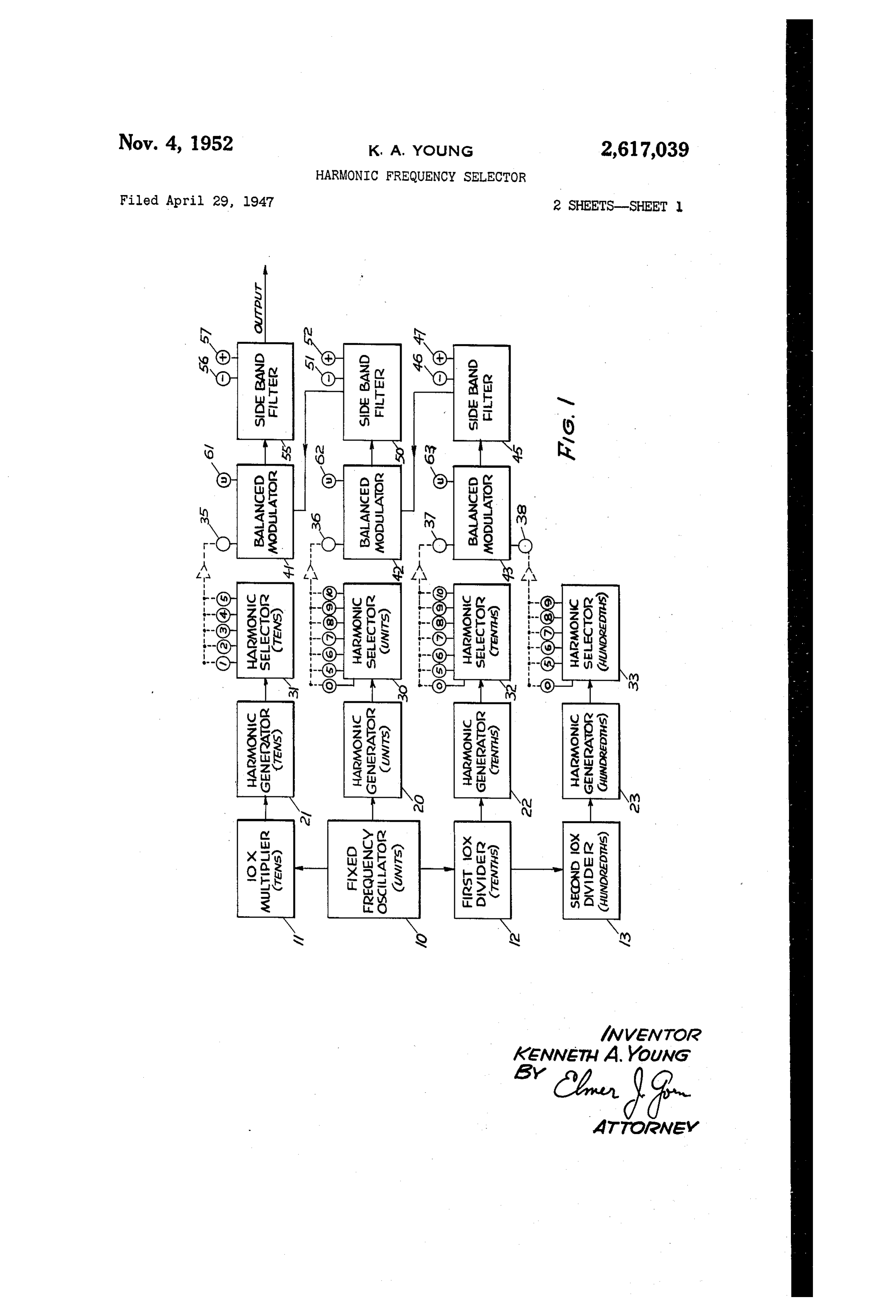
This invention relates in general to apparatus Fig. 1 illustrates in block diagram form an ap for generating an electric wave having a partic paratus for generating various frequencies from ular frequency from selected harmonics of a Selected harmonics of a single oscillator; and Single oscillator or a related group of Oscillators, Fig. 2 illustrates in electrical scheme a device and in particular to a device for automatically 5 for Selecting harmonics. Selecting a proper and most advantageous com The frequency generator illustrated in Fig. 1 bination of harmonics to provide a desired par is designed to provide any frequency in the band ticular frequency. from i0 megacycles per second to 50 megacycles In a paper published May 5, 1943, before the per second, in steps of 10 kilocycles per second. Wireless Section of the Institution of Electrical O This generator is similar in nature to that de Engineers, London, England, and later in the SCribed by Finden in the above-mentioned article, ''Journal of the Institution of Electrical Engi and only its essential elements and their inter neers,' vol. 90, part 3, December 1943, pages 165 relation will be described herein. A fixed fre to 180, inclusive, by H. J. Finden, there is de quency oscillator 10, which may be crystal con Scribed an apparatus for generating a desired fre trolled, is arranged to oscillate at 1 megacycle quency by synthesis from selected harmonics of per Second. A frequency multiplier is ac a group of harmonics and Subharmonics of a tuated by a portion of the output of the fixed Standard frequency, the apparatus yielding any frequency oscillator and in turn provides a 10 frequency that is harmonically related to a mull mega-Cycle per Second Wave, multiplying the ini tiple or a submultiple of the standard frequency. 20 tial frequency by ten. A first frequency divider In this apparatus, the functioning of the various 12 is also actuated by a portion of the output filters for the selection of proper harmonics, and of the fixed frequency oscillator G, and in turn Selection of the proper sidebands When har provides a Wave oscillating at 0.1 megacycles per monics are combined, is Only partly automatic, Second, dividing the initial frequency by ten. A and the lack of completely automatic functioning 25 Second frequency divider 3, actuated by the 0.1 of the synthesizer seriously limits the use thereof. megacycle per second Wave from the first di In the present invention, it is accordingly the vider 2, further divides the initial frequency main object to provide a computer which oper by ten to provide a wave oscillator at 0.01 mega ates or provides information for the operation cycle per second, or 10 kilocycles per second. of a frequency synthesizer of the above-described 30 There are now four sources O to 3, inclusive, kind in a fully automatic fashion. of fixed frequencies which are related to each It is another object of this invention to pro other in decade fashion.
Wide a method and means to combine selected Each of the decade fixed frequency sources harmonics of a single Oscillator or a related 0 to 3, inclusive, actuates a harmonic genera group of OScillators to provide an electric wave 35 tor 26, 2, 22, and 23, respectively. The har of a desired frequency in such a fashion that monic generators are substantially identical in electric waves of other frequencies that may be nature, but differ in that each is constructed and Simultaneously generated in the process of com arranged to oscillate at a fundamental frequency bination are spaced as far as possible infrequency Which is Substantially the same as the frequency from the desired Wave to permit adequate fil 40 of the particular decade source 0 to 3, inclu tering. Sive, by Whichit is actuated. Otherwise the har It is another object of the invention to pro monic generators may all be multivibrators, or vide means for automatically making a selec any other kind of oscillator or amplifier that is tion, than which there is none better, of the rich in harmonics.
proper harmonics required to generate a desired 45 The tens decade harmonic generator 2 feeds frequency. into a tens decade harmonic selector 3 which It is a further object of the invention to pro provides facilities for selecting any one of the vide such means which is simple to operate, re first five harmonics of 10 megacycles per sec liable in Operation, and is constructed with a ond, namely 10, 20, 30, 40, or 50 megacycles per minimum of complexity. 50 Second. The selector may comprise a set of se The foregoing and other and further objects lective filters, each of which passes one of the of the invention will become apparent from the desired frequencies, and is equipped with five following description of an exemplary embodi output terminals labelled , 2, 3, 4, and 5, re ment thereof, reference being had to the accom Spectively, each terminal being for the corre panying drawings, wherein: 55 Sponding numbered harmonic of 10 megacycles
Page 4
per second. Thus terminal of the tens decade The first balanced modulator 4f furnishes two Selector 3 is a 10 mc./sec. output terminal, ter output signals having frequencies which are, re minal 2 is a 20 m.c./Sec. Output terminal, and SO Spectively, the Sum and the difference of the on to terminal 5 which is the 50 m.c./sec. output Selected frequency from the tens harmonic selec terminal. The harmonic generator and Selector tor and the frequency provided by the second is preferably built as a unit in which each fre Sideband filter 58, and furnishes these two signals quency selective circuit (selective filters) is part to a third Sideband filter 55. This filter furnishes of the generator. For an example, it may be either the sum frequency or the difference fre an Over-driven amplifier whose plate circuit can quency as the final output frequency of the fre be tuned (or Switched) to the wanted harmonic. O quency generator, in accordance with which of Selection of the particular harmonic that is the tWO control terminals 56 or 57 thereof is en desired may be made in any fashion, and a new ergized.
method and apparatus for selecting harmonics Each balanced modulator 4 , 42, and 43 is pro Will be described below. The harmonic that is vided with an unbalance control terminal 6, 62, Selected is fed into a first balanced nodulator ?5 and 63, respectively, by the energization of which 4 through an input terminal 35. the modulator is unbalanced and made to am Considering now the units decade, the unitS plify Only the signal fed thereinto from the en harmonic generator 26 feeds into a units har ergizing harmonic selector. A modulator is un monic selector 38, Which provides the fifth, sixth, balanced when only one frequency is fed into it, Seventh, eighth, ninth, and tenth harmonics of 1 20 that is, when a harmonic selector feeding it is mc./sec. at correspondingly numbered terminals SetThe of 'Zero.'
frequency generator provides a desired fre 5, 6, 7, 8, 9, and 0, respectively. There is also a terminal labelled zero from which no signal is quency as follows.
available, for a purpose that will appear below. A ASSuline that an output frequency of 41.81 Selected harmonic of 1 inc./sec. is fed into a sec 25 negacycles per Second is desired. This frequency Ond balanced modulator 42 at an input terminal might be arrived at by adding the first hundredth 36 thereof. In the tenths decade, a tenths har decade harmonic Or 0,01 mc./sec. from the hun monic Selector 32 is actuated by the tenths har dredths harmonic Selector 33 and the eighth monic generator 22 and provides the fifth, sixth, tenths decade harmonic, or 0.80 m.c./sec. from the Seventh, eighth, ninth, and tenth harmonics of 30 tenths harmonic selector 32 in the third balanced 0.1. Inc./sec. at correspondingly numbered output nodulator 43, then adding the resulting 0.81 terminals 5, 6, 7, 8, 9, and 0, respectively. Again mc./sec. signal to the first units harmonic or there is a Zero terminal at which no signal is 1.0 m.c./sec. from the units harmonic selector. 30 available, and any one of these output terminals in the Second balanced modulator 42, and finally may selectively be connected to a third balanced 35 adding the then resulting 1.81 mc./Sec. signal to modulator 43 at a first input terminal 37 there the fourth tens harmonic, or 40 m.c./sec. from of. The hundredths decade has a hundredths frequency the tens harmonic Selector 3, to yield an output harmonic selector 33 which provides the fifth, of 41.81 mc./sec. The sideband filters Sixth, Seventh, eighth, and ninth harmonics of 10 45, 59, and 55 are all arranged to provide the kc./sec. at correspondingly numbered output 40 Sum frequency rather than the difference fre terminals 5, 6, 7, 8, and 9, respectively, and a zero quency in each case.
Signal at a zero terminal. Any one of the output The procedure just outlined has a defect in terminals of the hundredths harmonic selector that the Sun and difference frequencies existing 33 may be selectively connected to the third in certain of the balanced modulators are too balanced modulator 43 at a second input terminal 4. 5 close together to permit clear cut separation of 38 thereof. the two modulator output frequencies in the sub The third balanced modulator 43 feeds its out Sequent sideband filter. For example, when the put, which consists almost entirely of two signals frequencies 0.01 me../sec. and 0.80 m.c./sec. are fed of which the frequencies are, respectively, the sum into the third balanced modulator 43, the sum and the difference of the frequencies brought 50 frequency that results is 0.81 mc./sec., while the in at the input terminals 37 and 38, to a first difference frequency is 0.79 mc/sec., the separa sideband filter 45. This filter has two control tion being only 0.02 mc./sec. Separation of 0.81 terminals 46 and for determining whether the mc./sec. and 0.79 m.c./sec. in the first side band filter shall furnish the sum frequency (--) or the filter 35 is very difficult. Assuming however, that difference frequency (-). Determination is 55 0.81 mc./sec. can be separated, the mixture of made by furnishing a voltage to the terminal 0.81 mc/sec. and 1.0 mc/sec. in the second bal bearing the desired algebraic sign (--) or (-), anced modulator 2 yields the sum frequency of as Will appear below. The output of the first 1.81 mc./sec. and the difference frequency of 0.19 Sideband filter 5 is then fed into the second mc./Sec. Which are Widely separate, and hence balanced modulator 42, where this output and the 60 easily Separated in the second sideband filter 5); Selected output from the units harmonic Selec but, the Subsequent mixture of 1.81 mc./sec. and tor 30 are operated upon. 40 m.c./sec. in the first balanced modulator & The Second balanced modulator A2 also fur yields the sum frequency of 41.81 mc./sec. and nishes two signals which have, respectively, the the difference frequency of 38.19 m.c./sec., which Sum and difference frequencies of the two input 65 again are too close together for easy separation signals, and these two sum and difference fre in the third sideband filter 55. quency signals are fed into a second sideband The Separation of the sum and difference fre filter 59, which in turn furnishes only one, the quencies furnished by any one of the modulators Sum or the difference frequency, in accordance 4, 42, or 63 should be at least as great as the with the condition of the control terminals 3 70 difference between two adjacent harmonic orders. and 52. Again a voltage is provided to the ter of the higher decade employed to actuate the minal bearing the desired algebraic sign (--) or modulator. The process of synthesis of the de (-) to select the desired frequency in the out Sired frequency, 41.81 m.c./sec., can be carried out. put. The output of the second sideband filter 50 to achieve such good separation by proper selec is fed into the first balanced modulator 4. 75 tion of sum and difference frequencies from the
Page 5
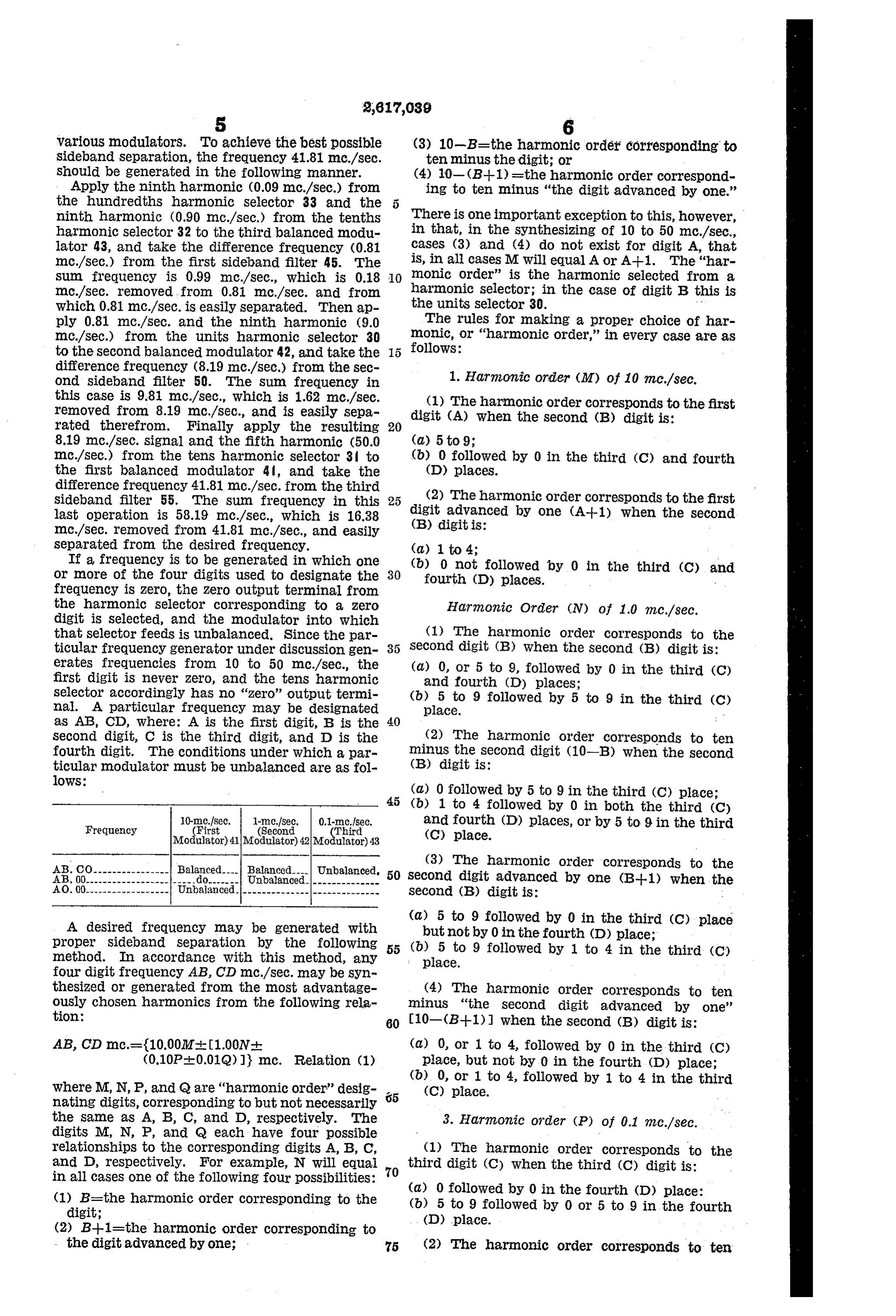
various modulators. To achieve the best possible (3) 10-B=the harmonic order corresponding to sideband separation, the frequency 41.81 mc./sec. ten minus the digit; or Should be generated in the following manner. (4) 10- (B-1) =the harmonic order correspond Apply the ninth harmonic (0.09 mc./sec.) from ing to ten minus "the digit advanced by one.' the hundredths harmonic Selector 33 and the ninth harmonic (0.90 m.c./sec.) from the tenths There is one important exception to this, however, harmonic selector 32 to the third balanced modul in that, in the Synthesizing of 10 to 50 m.c./sec., lator 43, and take the difference frequency (0.81 cases (3) and (4) do not exist for digit A, that mc./sec.) from the first sideband filter 45. The is, in all cases M will equal A or A-1. The “har sum frequency is 0.99 mc./sec., which is 0.18 O monic Order' is the harmonic selected from a mc./sec. removed from 0.81 mc./sec. and from the harmonic selector; in the case of digit B this is which 0.81 mc./sec. is easily separated. Then ap units selector 30.
ply 0.81 mc./sec. and the ninth harmonic (9.0 The rules for making a proper choice of har mc./sec.) from the units harmonic selector 30 monic, or "harmonic order,' in every case are as to the second balanced modulator 42, and take the follows: difference frequency (8.19 mc./sec.) from the Sec ond sideband filter 50. The Sum frequency in 1. Harmonic order (M) of 10 m.c./sec. this case is 9.81 mc./sec., which is 1.62 m.c./sec. (1) The harmonic order corresponds to the first removed from 8.19 mc./sec., and is easily sepa digit (A) when the second (B) digit is: rated therefrom. Finally apply the resulting 20 8.19 mc./sec. signal and the fifth harmonic (50.0 (a) 5 to 9;
mc./sec.) from the tens harmonic selector 3 to (b) 0 followed by 0 in the third (C) and fourth the first balanced modulator 4, and take the (D) places.
difference frequency 41.81 m.c./sec. from the third sideband filter 55. The Sum frequency in this 25 (2) The harmonic order corresponds to the first last operation is 58.19 m.c./sec., which is 16.38 digit advanced by one (A-1) when the second mc./sec. removed from 41.81 mc./sec., and easily (B) digit is:
separated from the desired frequency. (d) 1 to 4;
If a frequency is to be generated in which one or more of the four digits used to designate the 30 (b)fourth 0 not followed by 0 in the third (C) and
(D) places.
frequency is zero, the Zero output terminal from the harmonic Selector corresponding to a Zero Harmonic Order (N) of 1.0 me/sec. digit is selected, and the modulator into which that selector feeds is unbalanced. Since the par (l) The harmonic order corresponds to the ticular frequency generator under discussion gen 35 Second digit (B) when the second (B) digit is: erates frequencies from 10 to 50 m.c./sec., the (d) 0, or 5 to 9, followed by 0 in the third (C) first digit is never Zero, and the tens harmonic and fourth (D) places;
selector accordingly has no "Zero” output termi (b)place.
5 to 9 followed by 5 to 9 in the third (C na. A particular frequency may be designated as AB, CD, Where: A is the first digit, B is the 40
Second digit, C is the third digit, and D is the (2) The harmonic order corresponds to ten fourth digit. The conditions under which a par minus the Second digit (10-B) when the second ticular modulator must be unbalanced are as fol (B) digit is: loWS:
(a) 0 followed by 5 to 9 in the third (C) place;
(b) 1 to 4 followed by 0 in both the third (C)
Frequency
(First
(Second
Third and fourth (D) places, or by 5 to 9 in the third
Modulator) 41||Modulator) 42||Modulator) 43 (C) place.
AB. CO ---------------- Balanced. Balanced. Unbalanced (3) The harmonic order corresponds to the
AB. 00.------------------|----- do------- Unbalanced-|-------------- 50 Second digit advanced by one (B-1)when th AO. 00.------------------ Unbalanced.---------------------------- Second (B) digit is: A desired frequency may be generated with (a) 5 to 9 followed by 0 in the third (C) place proper sideband separation by the following 55 (b)but5 not by 0 in the fourth (D) place; to 9 followed by 1 to 4 in the third (C) method. In accordance with this method, any place. four digit frequency AB, CD mc./sec. may be Syn thesized or generated from the most advantage (4) The harmonic order corresponds to tem ously chosen harmonics from the following rela minus "the second digit advanced by one' tion: 60 10-(B+1) when the second (B) digit is: AB, CD mc.={10.002M-4: [1.00N (a) 0, or 1 to 4, followed by O in the third (C) (0.10P-+-0.01Q)]} mc. Relation (1) place, but not by 0 in the fourth (D) place; (b) 0, or 1 to 4, followed by 1 to 4 in the third where M, N, P, and Q are "harmonic order' desig (C) place. nating digits, corresponding to but not necessarily the same as A, B, C, and D, respectively. The 3. Harmonic order (P) of 0.1 mc./sec. digits M, N, P, and Q each have four possible relationships to the corresponding digits A, B, C, (1) The harmonic order corresponds to the and D, respectively. For example, N will equal third digit (C) when the third (C) digit is: in all cases one of the following four possibilities: 70 (1) B-the harmonic order corresponding to the (a) 0 followed by 0 in the fourth (D) place: digit; (b) 5 to 9 followed by 0 or 5 to 9 in the fourth (D) place.
(2) B--1=the harmonic order corresponding to the digit advanced by One; 75 (2) The harmonic order corresponds to ten
Page 6
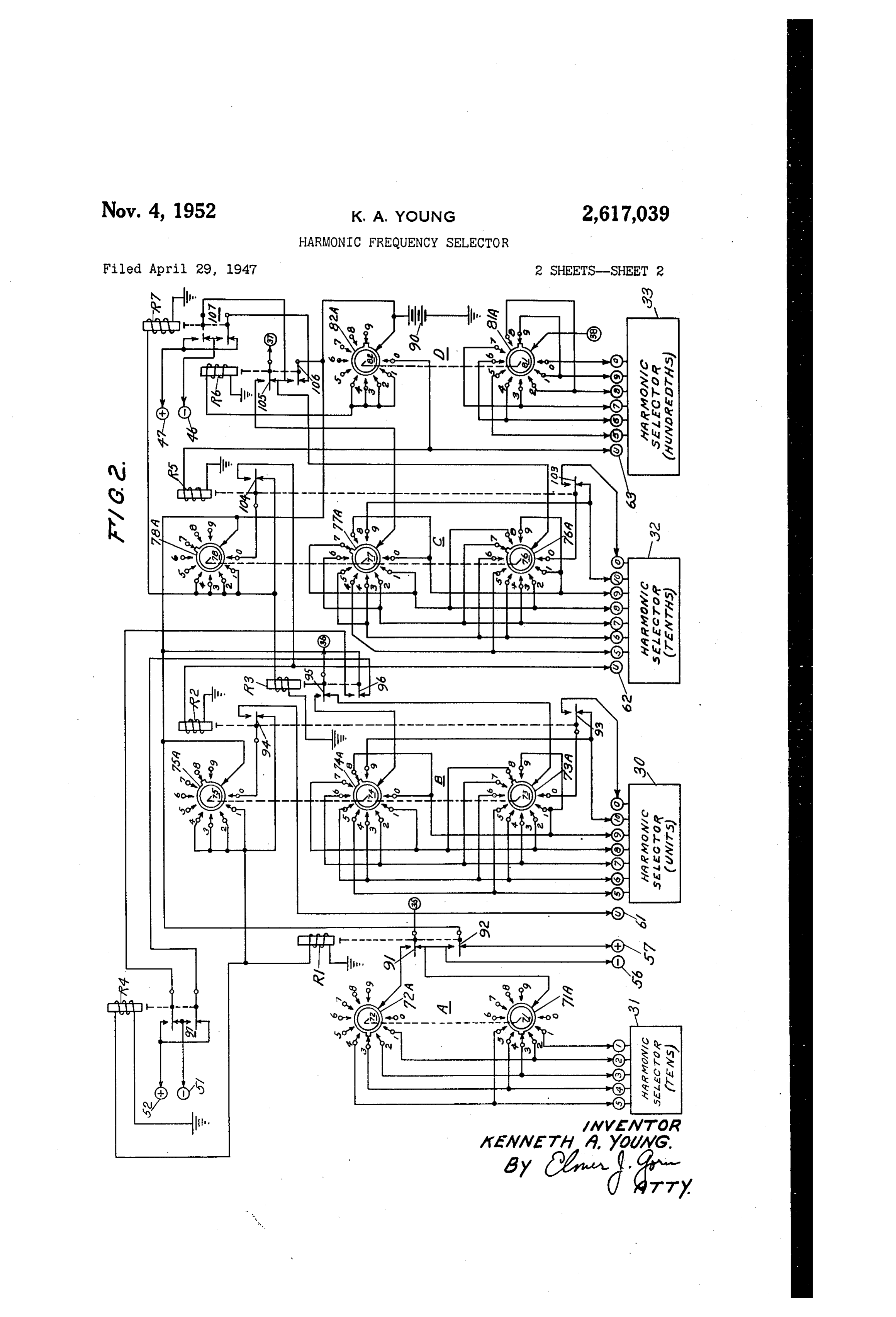
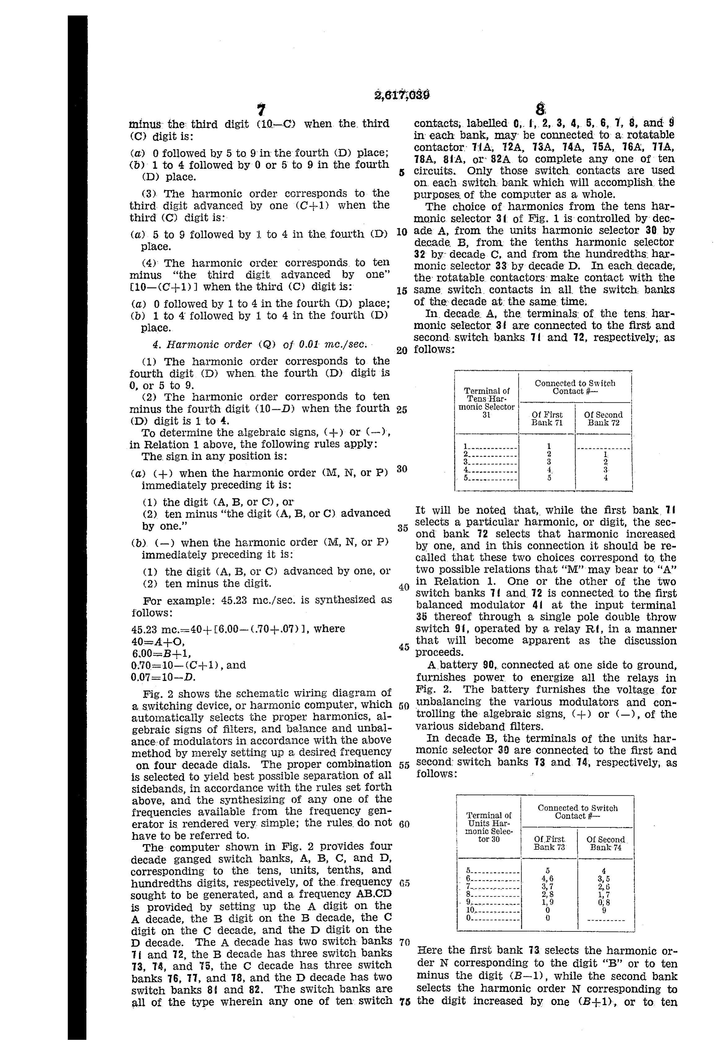
minus the third digit (10-C) when the third contacts, labelled 0, f, 2, 3, 4, 5, 6, 7, 8, and S (C) digit is: in each bank, may be connected to a rotatable (a) 0 followed by 5 to 9 in the fourth (D) place; contactor TÍA, 2A, 73A, 74A, 75A, 76A, 77A, (b) 1 to 4 followed by 0 or 5 to 9 in the fourth 78A, 8 A, or 32A to complete any one of ten (D) place. circuits. Only those Switch contacts are used On each Switch bank which will accomplish the (3) The harmonic order corresponds to the purposes of the computer as a whole. third digit advanced by one (C-1) when the The choice of harmonics from the tens har third (C) digit is: nonic Selector 3 of Fig. 1 is controlled by dec (a) 5 to 9 followed by to 4 in the foulth (D) 0. ade A, from the units harmonic selector 30 by place. decade B, from the tenths harmonic selector 32 by decade C, and from the hundredths har (4) The harmonic order corresponds to ten monic Selector 33 by decade D. In each decade, minus “the third digit advanced by one' the rotatable contactors make contact with the 10- (C-1)) when the third (C) digit is: 5 Same Switch. Contacts in all the switch banks (a) 0 followed by 1 to 4 in the fourth (D) place; of the decade at the same time, (b) 1 to 4 followed by 1 to 4 in the fourth (D) In decade A, the terminals of the tens har place. monic Selector 3 are connected to the first and 4. Harmonic order (Q) of 0.01 mic./sec. . Second switch banks 7 and 72, respectively, as 20 follows:
(1) The harmonic order corresponds to the fourth digit (D) when the fourth (D) digit is 0, or 5 to 9. Connected to Switch Terminal of Contact i (2) The harmonic order corresponds to tem TenSi Har.
ninus the fourth digit (10-D) when the fourth 25 moniº Selector
(D) digit is 1 to 4. Balik 71 Bank 72 To determine the algebraic signs, (--) or (-), - -
in Relation 1 above, the following rules apply: l------------- -------------- The sign in any position is: 2-------------
(a) (--) when the harmonic order (M, N, or P) 5------------- 5 ? immediately preceding it is:
(1) the digit (A, B, or C), or (2) te minus “the digit (A, B, or C) advanced It will be noted that, while the first bank 1 í by one.' Selects a particular harmonic, or digit, the sec Ond bank 2 Selects that harmonic increased (b). (-) when the harmonic order (M, N, or P) by one, and in this connection it should be re immediately preceding it is: called that these two choices correspond to the (l) the digit (A, B, or C) advanced by one, or two possible relations that “M” may bear to 'A' (2) ten minus the digit. 40 in Relation 1. One or the other of the two For example: 45.23 innc./sec. is Synthesized as Switch banks 7 and 12 is connected to the first follows:
balanced modulator 4 at the input terminal 35 thereof through a single pole double throw 45.23 mc.= 40 -- [6.00 — (.70--.07) ], where Switch 9, Operated by a relay Rf, in a manner 40s. Al-O, that will become apparent as the discussion 6,00-B-1, proceeds.
0.70=10- (C-1), and A battery 90, connected at one side to ground, 0.07-10-D. furnishes power to energize all the relays in Fig. 2 shows the schematic wiring diagran of Fig. 2. The battery furnishes the voltage for a switching device, or harmonic computer, which O unbalancing the various modulators and con automatically selects the proper harmonics, al trolling the algebraic signs, (--) or (-), of the gebraic signs of filters, and balance and unbal Various Sideband filters. ance of modulators in accordance with the above In decade B, the terminals of the units har method by merely setting up a desired frequency monic Selector 30 are connected to the first and on four decade dials. The proper combination 55 Second Switch banks 73 and 74, respectively, as is selected to yield best possible separation of all follows:
sidebands, in accordance with the rules set forth above, and the synthesizing of any one of the w Connected to Switch frequencies available from the frequency gen Terminal of Contact if erator is rendered very, simple; the rules do not 60 UnitS Har- – ! Inonic Selec have to be referred to. to 30 OfFirst. Of Second The computer shown in Fig. 2 provides four i Bank 73 Bank 74 decade ganged Switch banks, A, B, C, and D, corresponding to the tens, units, tenths, and 5 4. hundredths digits, respectively, of the frequency (5 4, 6 3,5
sought to be generated, and a frequency ABCD 2,8
is provided by setting up the A digit on the 0 9 A decade, the B digit on the B decade, the C 0. digit on the C decade, and the D digit on the
D decade. The A decade has two switch banks 70
Ti i and 72, the B decade has three switch banks Here the first bank 73 selects the harmonic or 73, T4, and 5, the C decade has three Switch der N corresponding to the digit “B” or to ten banks 76, 7, and 78, and the D decade has two minus the digit (B-1), while the second bank switch banks 8 and 82. The switch banks are Selects the harmonic order N corresponding to all of the type wherein any one of ten switch the digit increased by one (B-1), or to ten
Page 7
minus “the digit increased by one' (10-(B-1-1)l, in accordance with the rules set forth above Connected to Switch concerning the relationship between 'N' and Terminal of
Tenths Har
Contacti
'B' in Relation 1. The third switch bank 5 of monic Selec decade B energizes relay Rd from the battery Of First Bank 76
Of Second
Bank 77 90 when decade B is in any one of the first, second, third, or fourth switch positions.
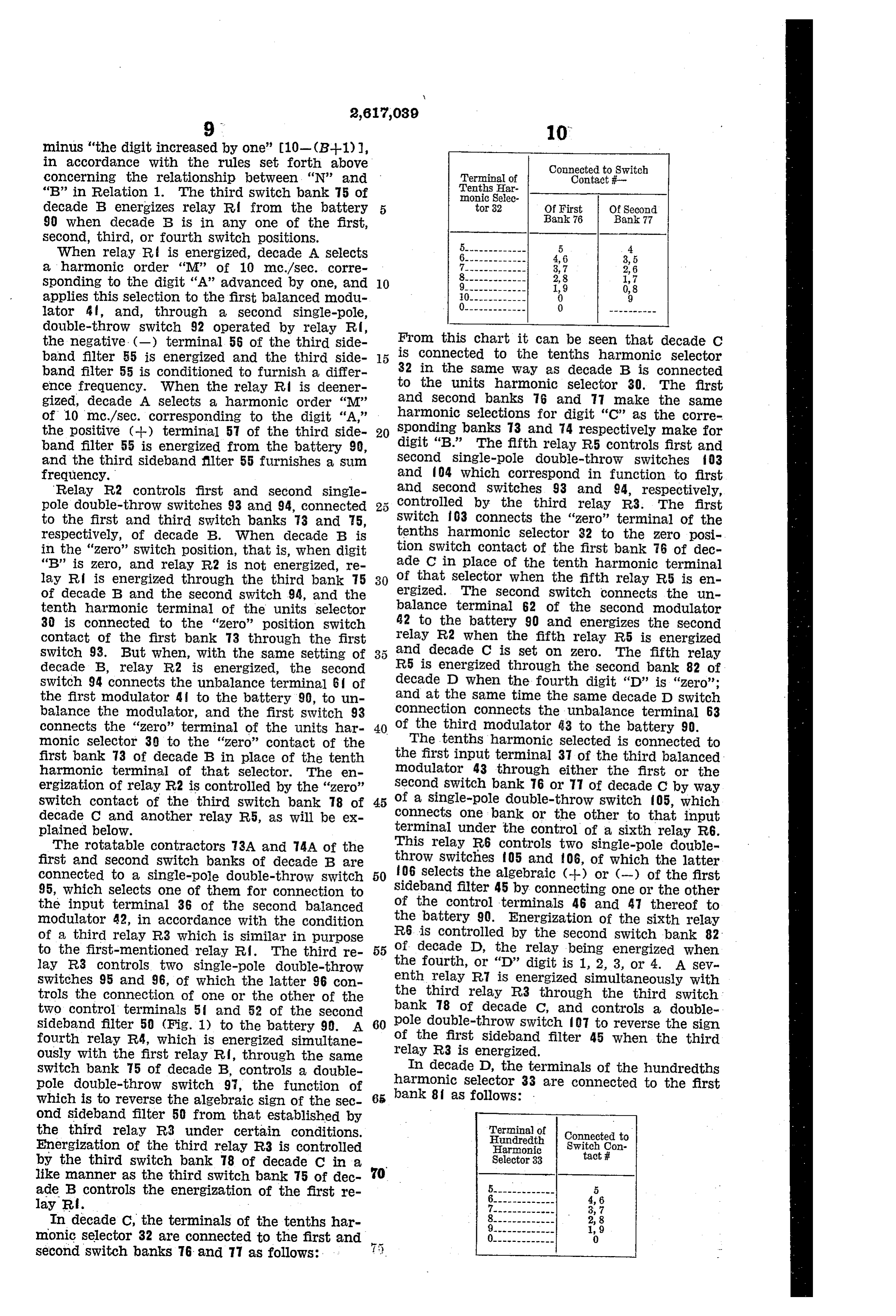
When relay R is energized, decade A Selects a harmonic order 'M' of 10 m.c./sec. corre sponding to the digit 'A' advanced by one, and 10 applies this selection to the first balanced modul lator 4 f, and, through a second single-pole, double-throw switch 92 operated by relay R, the negative. (-) terminal 56 of the third side From this chart it can be seen that decade C band filter 55 is energized and the third side 15 is connected to the tenths harmonic selector band filter 55 is conditioned to furnish a differ 32 in the same way as decade B is connected ence frequency. When the relay R is deener to the units harmonic selector 30. The first gized, decade A selects a harmonic order "M' and Second banks 76 and 77 make the same of 10 mc./sec. corresponding to the digit “A,” harmonic selections for digit 'C' as the corre the positive (--) terminal 57 of the third side 20 sponding banks 73 and 74 respectively make for band filter 55 is energized from the battery 9, digit "B.' The fifth relay R5 controls first and and the third sideband filter 55 furnishes a Sulm Second single-pole double-throw switches iO3 frequency. and 04 which correspond in function to first Relay R2 controls first and second single and Second switches 93 and 94, respectively, pole double-throw switches 93 and 94, connected controlled by the third relay R3. The first to the first and third switch banks 73 and 5, Switch 03 connects the “Zero' terminal of the respectively, of decade B. When decade B is tenths harmonic selector 32 to the zero posi in the 'zero' switch position, that is, when digit tion Switch contact of the first bank 6 of dec 'B' is zero, and relay R2 is not energized, re a de C in place of the tenth harmonic terminal lay Ri is energized through the third bank 75 30 of that selector when the fifth relay R5 is en of decade B and the second switch 94, and the ergized. The Second switch connects the un tenth harmonic terminal of the units selector balance terminal 62 of the second modulator 30 is connected to the “Zero' position switch 42 to the battery 90 and energizes the second contact of the first bank 73 through the first relay R2 when the fifth relay R5 is energized switch 93. But when, with the same setting of and decade C is set on zero. The fifth relay decade B, relay R2 is energized, the second R5 is energized through the second bank 82 of switch 94 connects the unbalance terminal 6 of decade D when the fourth digit 'D' is “Zero'; the first modulator 4 to the battery 90, to un and at the Same time the same decade D switch balance the modulator, and the first switch 93 connection connects the unbalance terminal 63 connects the 'zero' terminal of the units har 40 of the third modulator 43 to the battery 90. monic selector 30 to the 'zero' contact of the The tenths harmonic selected is connected to first bank 73 of decade B in place of the tenth the first input terminal 37 of the third balanced harmonic terminal of that Selector. The en modulator 43 through either the first or the ergization of relay R2 is controlled by the "zero” second switch bank 76 or TT of decade C by way SWitch contact of the third switch bank 78 of 45 of a single-pole double-throw switch 05, which decade C and another relay R5, as will be ex connects one bank or the other to that input plained below. terminal under the control of a sixth relay R6. The rotatable contractors 3A and 4A of the This relay R6 controls two single-pole double first and Second Switch banks of decade B are throw Switches 05 and 06, of which the latter connected to a single-pole double-throw Switch 50 06 selects the algebraic (--) or (-) of the first 95, which selects one of them for connection to sideband filter 45 by connecting one or the other the input terminal 36 of the Second balanced of the control terminals 46 and 47 thereof to modulator 42, in accordance with the condition the battery 90. Energization of the sixth relay of a third relay R3 which is similar in purpose R6 is controlled by the second switch bank 82 to the first-mentioned relay R. The third re 55 of decade D, the relay being energized When lay R3 controls two single-pole double-throw the fourth, or 'D' digit is 1, 2, 3, or 4. A sev Switches 95 and 96, of which the latter 96 con enth relay R is energized simultaneously with trols the connection of one or the other of the the third relay R3 through the third switch: two control terminals 5 and 52 of the Second bank 78 of decade C, and controls a double sideband filter 50 (Fig. 1) to the battery 99. A 60 pole double-throw switch 07 to reverse the sign fourth relay R4, which is energized simultane of the first sideband filter 45 when the third ously with the first relay Rd, through the same relay R3 is energized.
switch bank 75 of decade B, controls a double In decade D, the terminals of the hundredths pole double-throw switch 97, the function of harmonic Selector 33 are connected to the first which is to reverse the algebraic sign of the Sec 65 bank 8 as follows: .
ond sideband filter 50 from that established by the third relay R3 under certain conditions. Terminal of Hundredith Connected to
Energization of the third relay R3 is controlled Harmonic Switch Con tact # by the third switch bank 78 of decade C in a Selector 33 like manner as the third Switch bank 75 of dec ade B controls the energization of the first re 4, 6 lay R.
In decade C, the terminals of the tenths har monic selector 32 are connected to the first and second switch banks 76 and 77 as follows:
Page 8
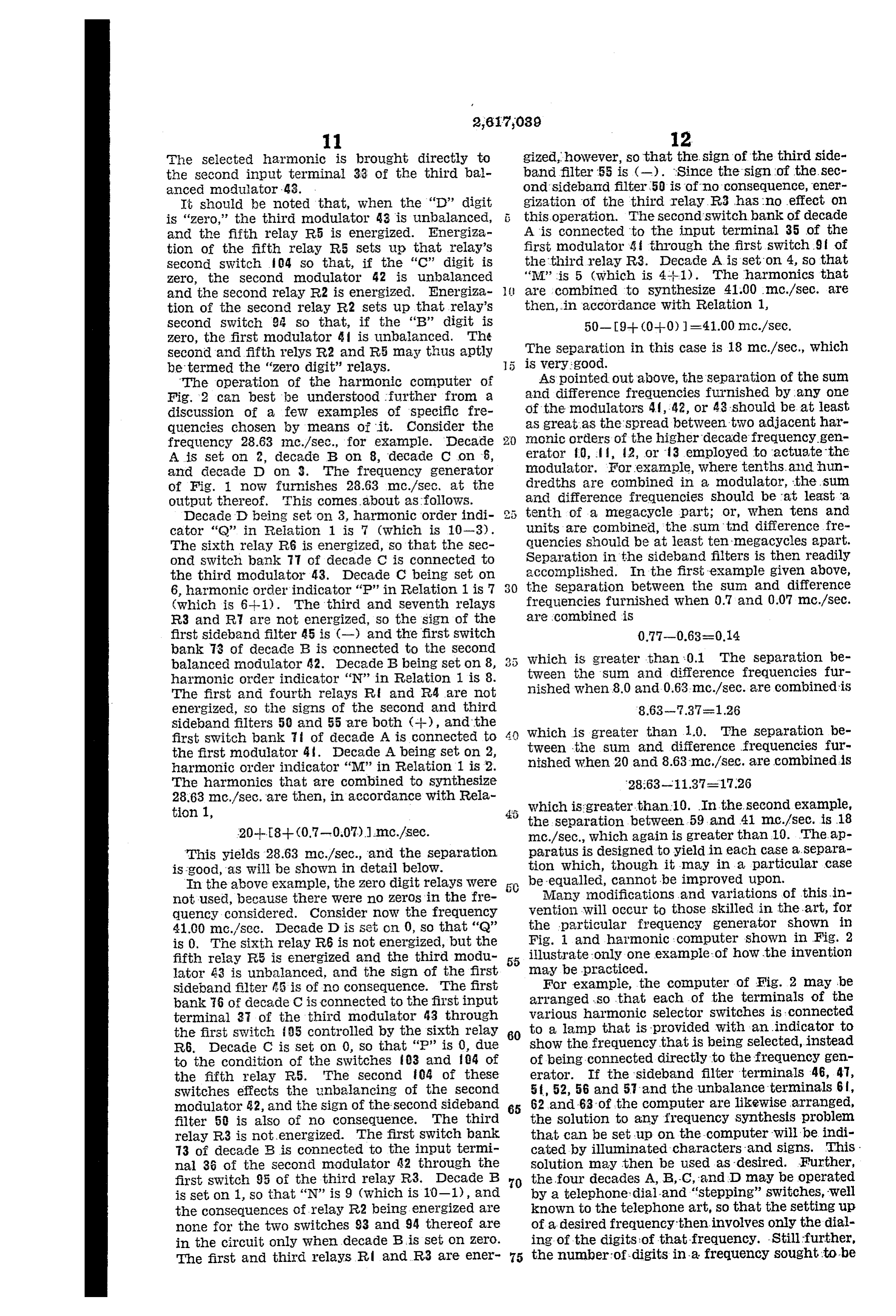
The selected harmonic is brought directly to gized, however, so that the sign of the third side the Second input terminal 33 of the third bal band filter 55 is (-). Since the sign of the sec anced modulator - 433. Ond Sideband filter 50 is of no Consequence, ener It should be noted that, when the 'D' digit gization of the third relay R3 has no effect on is "Zero,' the third modulator 43 is unbalanced, 5 this operation. The second Switch bank of decade and the fifth relay R5 is energized. Energiza A is connected to the input terminal 35 of the tion of the fifth relay R5 sets up that relay's first modulator 4 through the first switch 9 f of Second switch 04 so that, if the 'C' digit is the third relay R3. Decade A is set on 4, so that Zero, the Second modulator 42 is unbalanced 'M' is 5 (which is 4-1). The harmonics that and the Second relay R2 is energized. Energiza are combined to synthesize 41.00 m.c./sec. are tion of the second relay R2 sets up that relay's then, in accordance with Relation 1, Second switch. 9 is so that, if the 'B' digit is 50-9-- (0-0) =41.00 m.c./sec. Zer0, the first modulator & I is umbalanced. Th?
Second and fifth relys R2 and R5 may thus aptly The Separation in this case is 18 mo./sec., which be termed the "zero digit' relays. is very good.
The Operation of the harmonic computer of AS pointed out above, the separation of the sum Fig. 2 can best be understood further from a and difference frequencies furnished by any one discussion of a few examples of specific fre of the modulators 4,42, or 43 should be at least quencies chosen by means of it. Consider the aS great as the Spread between two adjacent har frequency 28.63 Inc./sec., for example. Decade monic orders of the higher decade frequencygen A is Set on 2, decade B on 8, decade C on 6, erator 0, . , 2, or 3 employed to actuate the and decade D on 3. The frequency generator IModulator. For example, Where tenths. and hun of Fig. i now furnishes 28.63 mc./sec. at the dredths are combined in a modulator, the sum Output thereof. This comes about as follows. and difference frequencies should be at least a Decade D being set on 3, harmonic order indi tenth of a megacycle part; or, when tens and cator 'Q' in Reiation 1 is 7 (which is 10-3). units are combined, “the sum “t?nd difference fire The Sixth relay R6 is energized, so that the sec quencies should be at least ten-megacycles apart. Ond Switch bank 7 of decade C is connected to Separation in the sideband filters is then readily the third nodulator 43. Decade C being set on accomplished. In the first example given above, 6, harmonic order indicator 'P' in Relation 1 is 7 30 the Separation between the Sun and difference (which is 6-i-i). The third and seventh relays frequencies furnished when 0.7 and 0.07 mc./sec. are combined is
R3 and R are not energized, so the sign of the first sideband filter 45 is (-) and the first switch 0.77?0.63=0.14 bank 3 of decade B is connected to the second Which is greater than 0.1. The separation be balanced modulator 42. Decade B being set on 8, tween the Sun and difference frequencies fur harmonic order indicator 'N' in Relation 1 is 8.
The first and fourth relays R and R4 are not nished when 8.0 and 0.63-mc./sec. are combined is energized, So the signs of the second and third
Sideband filters 50 and 55 are both (--), and the first Switch bank it of decade A is connected to 4 which is greater than 1.0. The separation be the first modulator 41. Decade A being set on 2, tween the sum and difference frequencies fur harmonic order indicator “M” in Relation 1 is 2. nished when 20 and 8.63 m.c./sec. are combined is The harmonics that are combined to synthesize 28.63 mc/sec. are then, in accordance with Rela which is greater than 10. In the second example, tion 1, the separation between 59 and 41 m.c.A.sec. is 18 20--8-- (0.7-0.07) ).mc./sec. mc./sec., which again is greater than 10. The ap This yields 28.63 m.c./sec., and the separation paratuS is deSigned tO yield in each case a. Separa is good, as will be shown in detail below. tion which, though it may in a particular case In the above example, the Zero digit relays were be equalled, cannot be improved upon. not used, because there Were no zeros in the fre Many modifications and variations of this.in quency considered. Consider now the frequency vention Will occur to those skilled in the art, for 41.00 mc./sec. Decade D is set on 0, so that 'Q' the particular frequency generator shown in is 0. The sixth relay R6 is not energized, but the Fig. 1 and haimonici computer shoWIn in Fig. 2 fifth relay FR5 is energized and the third modu 55 illustrate only one examples of how the invention lator A3 is unbalanced, and the sign of the first may be practiced.
Sideband filter is of no consequence. The first For example, the computer of Fig. 2 may be bank 6 of decade C is connected to the first input arranged so that each of the terminals of the terminal 3 of the third modulator 43 through various harmonic Selector Switches is connected the first Switch 95 controlled by the sixth relay 80 to a lamp that is provided with an indicator to R6. Decade C is set on 0, so that 'P' is 0, due show the frequency that is being selected, instead to the condition of the Switches 3 and 4 of of being connected directly to the frequency gen the fifth relay R5. The second 04 of these erator. If the sideband filter terminals 46, 47, Switches effects the unbalancing of the second 5t, 52, 56 and 57 and the unbalance terminals 6, modulator 32, and the sign of the second sideband 65 62 and 63 of the computer are likewise arranged, filter 50 is also of no consequence. The third the solution to any frequency Synthesis problem relay R3 is not energized. The first Switch bank that can be set up on the computer will be indi T3 of decade B is connected to the input termi cated by illuminated characters and Signs. This . na 36 of the second nodulator 42 through the Solution may then be used as desired. Further, first switch 95 of the third relay R3. Decade B 70 the four decades A, B, C, and D may be operated is set on 1, so that 'N' is 9 (which is 10-1), and by a telephones dial and 'stepping' Switches, well the consequences of relay R2 being energized are known to the telephone art, so that the setting up none for the two switches 93 and 94 thereof are of a desired frequency then involves only the dial in the circuit only when decade B is Set on Zero. ing of the digits of that frequency. Still further, The first and third relays R and R3 are ener 75 the number-of-digits in a frequency sought to be
Page 9
Synthesized by means of a computer in accord Second Switch means having a plurality of cir ance With this invention is not limited to four; cuit-making contacts for selecting the second in it may be any number greater or lesser. The dividual frequency N when set on one contact Computer may be constructed with more or few in accordance with the second digit B, first re er decades A, B, C, or D, it being particularly 5 lay Operated Switch means controlled by said sec noteworthy that decades B and C are similar, and Ond Switch means and arranged to condition the more like them may be added. All that is re Selection of Said first switch means in accordance quired is to set up the necessary rules for fre with the setting of said second switch means, quency. Synthesis in accordance with the method and second relay operated switch means con Set forth herein, and to construct the switching 0. trolled by both said first and second switch circuits in accordance with these rules. Actually, means and arranged to select said algebraic sign the decade system is not the only system that can (--) or (-) in accordance with the settings of be used, although it is the most convenient. A both Said first and second switch means, both System based on any other number grouping may Said first and second switch means being ar be used if desired, for example a system in which 5 ranged. So that at all times the difference be-, eights instead of tens are the basis from which tween M--N and IM-N is at least as great as harmonics are generated. However, a system of the difference between the frequencies (A-1) B tens offers the greatest simplicity, since it so is the frequency AB changed by one digit in the closely resembles the decade system used in nu first place.
merical representation. 20 3. In combination with a frequency generator The invention may have particular comi which is adapted to generate a frequency AB mercial value, for example, in the taxicab or cycles per unit time, where A and B are digits, trucking business, where each vehicle in the field by the combination of two individual frequencies may have a receiver and transmitter set up on M and N in the manner M-N, a switching system an individual frequency, and the main office may for automatically conditioning said generator to have a transmitter and receiver that is auto provide Said individual frequencies M and N. With matically tunable to a master oscillator fre a predetermined sign (--) or (-) comprising quency. Then a computer in accordance with first Switch means having a plurality of circuit the invention, if equipped with a telephone dial, making contacts connected to said generator and may be used to control a frequency generator 30 adapted to condition said generator to provide like that shown in Fig. 1, which in turn may be the first individual frequency M when set on one used as the master oscillator, to enable the main contact in accordance with the first digit A, sec office to call any vehicle in the field in the same ond Switch means having a plurality of circuit manner as one places a dial telephone call. making contacts connected to said generator and It is therefore desired that the appended 35 adapted to condition said generator to provide claims shall be given a broad interpretation the Second individual frequency N when set on commensurate with the scope of the invention One contact in accordance with the second digit within the art. B, and relay operated switch means controlled by What is claimed is: both said first and second switch means and 1. In the generation of a frequency AB cycle:S 40 connected to Said generator and adapted to con per unit time, where A and B are digits, by the dition Said generator to combine said individual combination of two individual frequencies M and frequencies M and N either additively or sub N in the manner IM-i-N, a switching System for tractively in accordance with the settings of both automatically selecting values of said individual Said first and second switch means, both said first frequencies M and N and the algebraic sign (--) and Second Switch means being arranged so that or (-) comprising first SWitch means having a at all times the difference between M--N and M-N is at least as great as the difference be plurality of circuits making contacts for Select tween the frequencies (A-+-1) B and AB, where ing the first individual frequency M. When Set (AH1) B is the frequency AB changed by one on one contact in accordance with the first digit
A, second switch means having a plurality of 50 digit in the first place.
4. In the generation of a frequency AB cycles circuits making contacts for selecting the Second individual frequency N when set on one contact per unit time, where A and B are digits, by the in accordance with the second digit B, and re combination of two individual frequencies M. lay operated switch means controlled by both and ing
N in the manner M-N, apparatus for choos most advantageous values for M and N which said first and second switch means and arranged comprises means settable in accordance with the to select said algebraic sign (--) or (—) im ac first digit A for relating M to A in one of cordance with the settings of both said first and four fashions, M=A, M=A-1, M-10-A, or second switch means, both said first and Second M=10-(Al--1); means settable in accordance switch means being arranged So that at all times wtih the Second digit B for relating N to B in the difference between M--N and M-N is at least 60 as great as the difference between the frequen One of four similar fashions, N=B, N-B-1, cies (A-+-1) B and AB, where (Al-H-1) B is the W=10-B, or N=10— (B-H-1) ; and means respon frequency AB changed by one digit in the first sive to the settings of said settable means to place. Select the algebraic sign between the M and N 2. In the generation of a frequency AB cycles 65 as Selected by said settable means, said settable means being constructed and arranged to select per unit time, where A and B are digits, by the values combination of two individual frequencies M and of M and N such that either M--N or M-N. yields the frequency AB cycles per unit time and
N in the manner M-N, a switching system for automatically selecting values of said individual 70 the Separation between M--N and M-N is a maximum.
frequencies M and N and the algebraic sign (--) 5. In the generation of a frequency ABCD or (-) comprising first switch means having a cycles per unit time where A, B, C, and D are plurality of circuit-making contacts for Select digits by Synthesis from four frequencies M, N, ing the first individual frequency M when set on P, and Q which are respectively harmonic orders one contact in accordance With the first digit A, of four basic frequency generators that are re
Page 10
lated to each other in decade fashion in the combined to produce the frequencies iM--N and manner MIN (PGR), apparatus for choos M-N, means in circuit with said nodulator for ing the most advantageous values for M, N, P, selecting one of said products, and means in cir and Q and the most advantageous algebraic signs cuit With said modulator for causing the un which comprises means Settable in accordance balance thereof, a switching Systern Connected with the first digit. A for relating M to A in One to said generator and modulator and governing of four fashions M=A, M=Al--1, M=10-A, or the operation thereof comprising first Switch M-10- (A-1); means settable in accordance means having a plurality of circuit making con with the second digit B for relating N to B in tacts connected to said generator and adapted one of four similar fashions N=B, N-B-I-1, O to condition said generator to provide the first Na-10-B, or N=10- (B-1); means settable in individual frequency MI When set on One con accordance with the third digit C for relating P tact in accordance with the first digit A, Second to C in one of four similar fashionS P=C, switch means having a plurality of circuit-mak PsC-1, P=10-C, or P-10- (C-1); means set ing contacts connected to said generator and table in accordance with the fourth digit D for 5 adapted to condition said generator to provide relating Q to D in one of four similar fashions the Second individual frequency N when Set on -D, Q-D-1, Q-10-D, or Q=10-(D-1-1) ; One contact in accordance with the Second digit and means responsive to the Settings of Said B, first relay operated Switch means controlled settable means to select the algebraic sign be by said switch means and connected to said tween P and Q as set by said C and D settable modulator and adapted to COndition Said modul means, between PiQ and N as set by Said B lator to combine said individual frequency M and Settable means, and between (PQ) -N and 4 Neither additively or subtractively in accord as set by said . A settable means, said settable ance with the setting of both first and second means being constructed and arranged to Select switch means, and second relay operated Switch values of M, N, P, and Q which provide the maxi 25 means controlled by said first and second Switch mum separation between the Sum and the dif means and connected to the unbalancing means ference in each algebraic operation, and Said of said modulator, and arranged to unbalance algebraic sign setting means being constructed Said modulator when one of Said digitS is zero. and arranged to provide that the algebraic sign in each position shall be plus when the harmonic 30 KENNETH. A. YOUNG. order M, N, or P preceding that sign is equal to the corresponding digit A, B, or C respectively REFERENCES CTED or i 0- (that digit--i), and minus When Said har The following references are of record in the monic order is equal to the corresponding digit file of this patent:
--1 or 10- (the corresponding digit). 35 UNITED STATES PAIENTS 6. In combination with a frequency generator which is adapted to generate a frequency AB Nunabe Nanne Date cycles per unit time, where A and B are digits, 2,131558 Granger ---------- Sept. 27, 1938 by the combination of two individual frequencies 2,231,634 Monk -------------- Feb. 11, 1941 M and N in the manner M+cN, a balanced modu s 2,401604 Bligh et al. ---------- June 4, 1946 lator wherein said individual frequencies are 2,450,696 Stenning ------------ Oct. 5, 1948
Provenance
- Collection
- Cited prior art
- Original PDF
- patentimages.storage.googleapis.com →
- Filed
- 1947-04-29
- Pages
- 10
- Method
- pdftotext (the PDF's own text layer) + pdftoppm 300dpi page scans
- Source
- Google Patents bibliographic record
- Granted
- 1952-11-04
- Inventors
- Kenneth A Young; Raytheon Manufacturing Co
- Transcribed from
- patentimages.storage.googleapis.com →