patent · US2220247
Burner for hydrocarbon gases
5 November 1940
Page 1
Nov. 5, 1940. F. S. KOCHENDORFER ET AL 2,220,247
BURNER FOR HYDROCARBON GASES
T -- - - , s
aZay agacy
SNS N S&N
S. sSysNN N
TMeave A. Mood
Page 2
Drawing sheet — no readable text.
Page 3
Patented Nov. 5, 1940
UNITED STATES PATENT OFFICE
BURNER FOR HYDROCARBON GASEs
Frederick S. Kochendorfer, Glendora, and Frank
E. Wood, Monrovia, Calif., assignors to Day &
Night Water Heater Company, Ltd., Monrovia,
Calif., a corporation of California. -
Application September 22, 1938, Serial No. 231,264
This invention relates to improvements in description when considered in connection with burners for hydrocarbon gases, and more par the accompanying drawings forming part hereof ticularly to burners of the type disclosed in and illustrating two embodiments of the inven
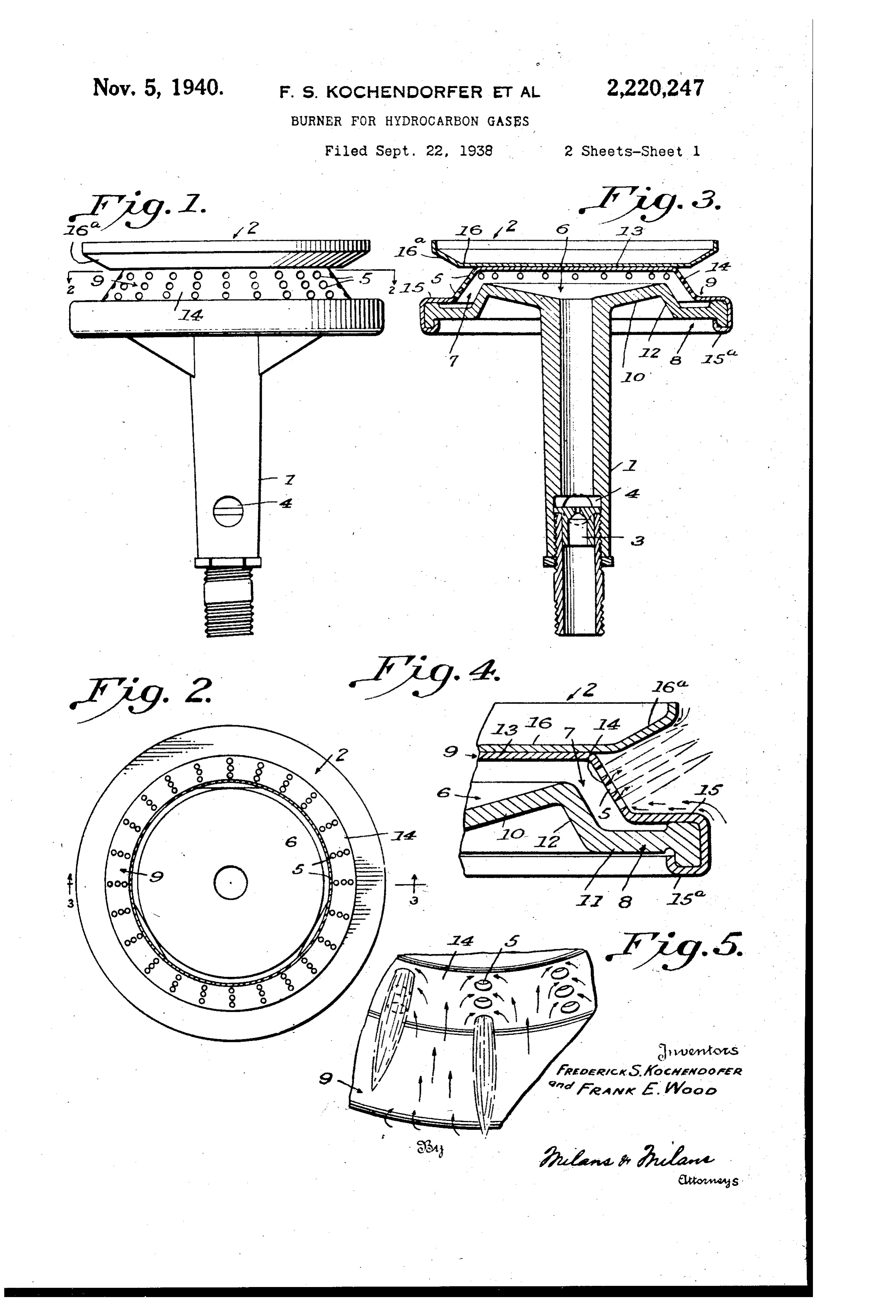
5 to William G. Carter. In the drawings: 5 Objects of the invention are to provide for . Figure l is an elevation of a burner con increasing the supply of secondary air and pre- structed in accordance with the present inven venting flashing-back into the burner, and to tion.
provide an improved burner that will operate Fig. 2 is a horizontal section on the line 2-2 l0 quietly and with a hotter flame. of Figure 1. O In the patent referred to above is disclosed a Fig. 3 is a vertical section on the line 3-3 of burner having a plurality of discharge jets along ' Figure 2.
the same with a flange below the discharge jets Fig. 4 is a fragmentary vertical section, and to cooperate therewith in causing a steady flow Fig. 5 is a fragmentary plan view, both on an 5 of incoming air along the inner side of the enlarged Scale, to illustrate the shape of the 15 flange and a steady outwardly flowing current of flames issuing from the discharge jets and the air next to the flames issuing from the discharge course of the incoming air currents relatively jets whereby the outwardly flowing current of air thereto.
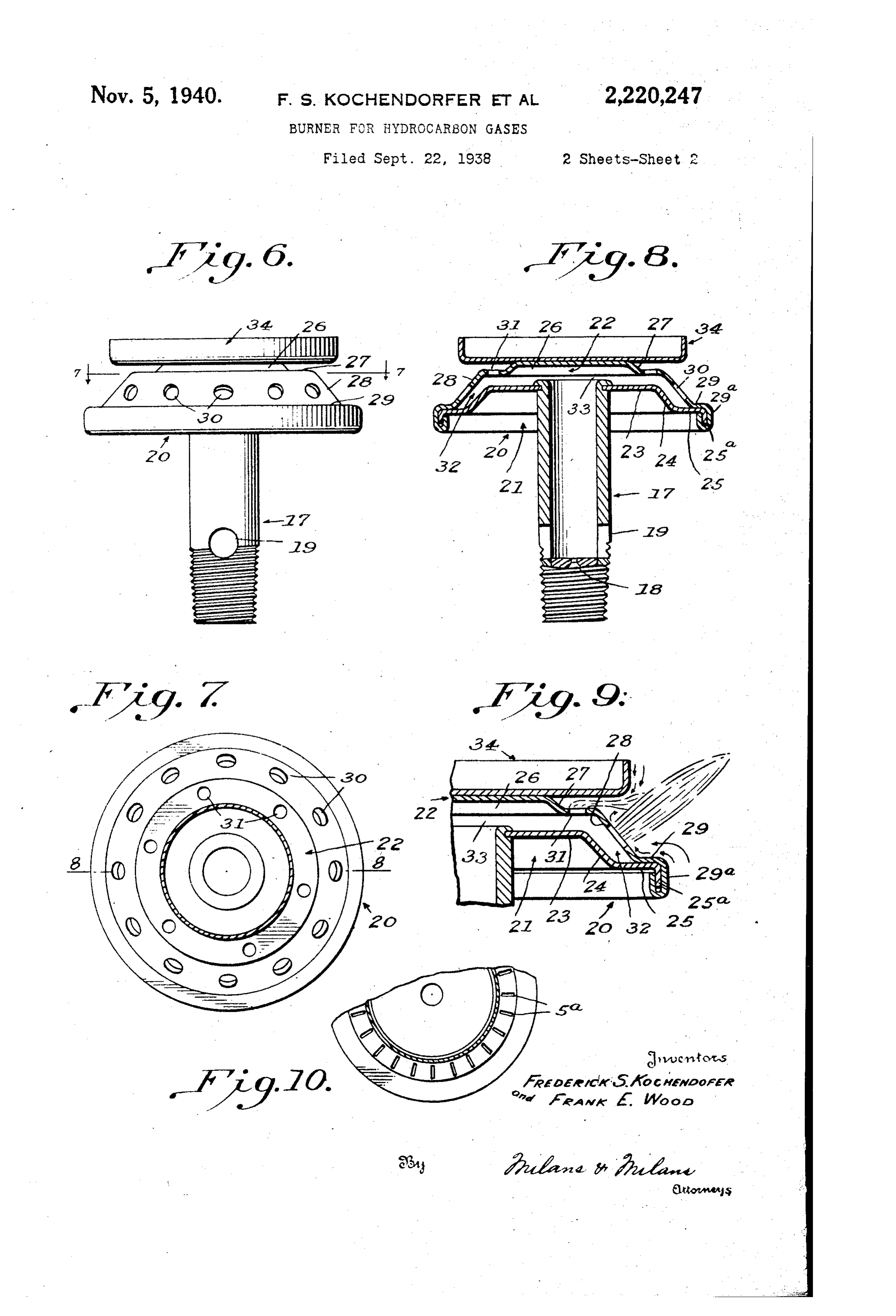
0 and the jeted mixture are retarded, and an Fig. 6 is an elevation of a modified construc- 20 additional supply of secondary air is carried to tion.
the exterior openings of the discharge jets. A Fig. 7 is a horizontal Section, on the line - particularly important novel feature of the pres- of Figure 6.
ent invention resides in a construction of the Fig. 8 is a vertical section on the line 8-8 of general kind referred to, in the spacing of the Figure 7. 25 discharge jets laterally from each other a suff- Fig. 9 is a fragmentary vertical Section, on an cient distance to leave room between the same enlarged scale, of the modified construction il for inwardly and outwardly flowing currents of lustrated in Figure 6.
air so that an incoming current of air enters be- Fig. 10 is a fragmentary top plan view of the tween the discharge jets and entirely surrounds construction of burner head illustrated in Figure 30 the flames, and the supply of secondary air is 2 provided with discharge jets in the form of materially increased. narrow slits.
Another important novel characteristic of the While two preferred embodiments of the in present invention resides in the particular con- vention are illustrated in the drawings, it will of struction including, in combination, a flange course be understood that minor changes and 35 above the discharge jets and a flange below the modifications may be made in the particular jets, each arranged to cooperate with the dis- constructions shown, and the invention may be charge jets to cause a steady flow of incoming embodied in other forms as will appeal to those air along the inner side of the flange, together skilled in the art and falling within the scope of with the arrangement of the discharge jets the appended claims, without departing from the 40 spaced apart sufficiently to create an inward spirit of the invention. 40 flowing current of air between the same. Referring to a detailed description of the par A further important novel feature of the in- ticular embodiment of the invention illustrated vention lies in the provision of a narrow paSSage- , in Figures 1 to 5 of the drawings, the construc way or throat portion leading from the interior tion shown comprises a mixing tube and an 4 of the burner to the plurality of discharge jets, enlarged upper head part 2. The mixing tube, 45 and which retards somewhat the flow of gas which communicates with the burner head cen through the discharge jets and at the same time trally thereof, has the conventional gas inlet 3 with the cooling effect of the mixing tube, di- and air inlets 4. .
minishes to a considerable degree the danger of The upper part or head of the burner is pro 50 flash-back. vided with a plurality of lateral discharge jets 5 The invention, with other objects, novel fea- and a mixture receiving chamber 6 with a nar tures and advantages thereof, and the particu- row annular passageway or throat 7 leading lar construction, combinations, and arrange- therefrom to the plurality of discharge jets. The 55 ments of parts comprising the same, will be un- burner head is shown as formed by a bottom 55 derstood from the hereinafter contained detailed plate 8 and a top plate 9. The bottom plate 8
Page 4
has a central upwardly and outwardly flaring burner necessary to prevent flashing-back, was part ?o and an outer annular horizontal portion so great as to force the igniting point away from joined to the central part O by a relatively the exterior opening of the discharge jet and short downwardly flaring wall portion 2. produce more or less noise.
5 The top plate 9 has a flat central part 3, an In our improved device hereinbefore described, intermediate downwardly flaring annular portion with the discharge jets spaced laterally farther 4 and an outer annular horizontal Wall portion apart a sufficient distance to leave room for the or flange 5, the latter fitting against an Outer free entrance of the incoming secondary air be marginal part of the horizontal wall portion tween the same, the incoming air entirely Sur O of the bottom plate and having an extension 5 rounds the individual flames, and the supply of O bent around the same to secure the plates to secondary air is materially increased. This in gether. The flange 5, as shown, connects with creased supply of secondary air makes it possible the downwardly flaring portion 4 near to the to use a much richer mixture, that is, one that rows of discharge jets 5 and extends outwardly contains a greater proportion of gas to the amount ls beyond the same at an angle therewith. The of air in the primary mixture. This difference is 5 discharge jets 5 preferably take the form of of great importance in that the richer mixture is openings in the downwardly flaring portion 4 of much less liable to flash-back into the burner. the top plate 9, and in this instance are relatively The narrow passageway or throat of the Small and arranged in vertical rows, as shown, burner serves to retard somewhat the flow of 920 but may be narrow slits if desired, as illustrated gas through the discharge jets 5 and this with 20 . in Figure 10 of the drawings, the discharge jets the cooling effect of the mixing tube is effective being designated 5 in this view. The burner is in diminishing to a considerable degree the dan provided with a cap member having a flat part ger of flash-back.
6, fitting against and secured to the flat cen The modified construction illustrated in Fig tral part 3 of the top plate, said cap member ures 6 to 9 of the drawings, is especially adapted 25 having an outwardly and upwardly flaring an to the Smaller forms of burners. This, like the nular marginal part or flange 6a extending construction hereinbefore described and illus above and outwardly beyond the discharge jets 5. trated in Figures 1 to 5, has upper and lower an The arrangement of the annular horizontal nular portions or flanges arranged relatively to 30 30 portion or flange 5 of the top plate and of the lateral discharge jets to control the supply of annular marginal part or flange 68 of the cap Secondary air to the flames issuing therefrom to member relatively to the discharge jets 5 is such bring the point of combustion back to the exte that each of said flanges acts to control the sup rior openings ofe the discharge jets. It has the ply of Secondary air to the flames issuing from lateral discharge jets spaced apart laterally 35 the discharge jets to bring the point of combus around the burner a sufficient distance so as to 35 tion back to the exterior openings of the same. create an inward flowing current of air inter Each flange cooperates with the discharge jets in mediate the discharge jets.
causing a steady flow of incoming air along the inner side of the flange and a stead outwardly larItpassageway also has the feature of the constricted annu leading from the mixing cham 40 flowing current of air next to the flames issuing ber to the discharge jets, but in this embodiment 40 from the discharge jets, whereby the outwardly of the invention instead of the vertical rows of flowing current of air and the jetted mixture are relatively small lateral discharge jet openings retarded. spaced circumferentially of the burner, single In accordance with the present invention, the larger discharge jet openings are provided, and 45 rows of discharge jets are spaced a sufficient dis secondary vertical discharge jet openings are 45 tance apart so as to create an inward flowing provided in the top wall of the burner inwardly current of air between the rows of discharge jets of the lateral discharge jets. which inflowing current of air feeds the out In Figures 6 to 9, 7 designates the mixing tube wardly flowing current created by the jets of having the usual gas inlet 8 and air inlets 9. 50 mixture. This Special arrangement is highly 20 is the enlarged upper head part composed of 50 inportant. By it the Supply of secondary air to a pair of plates 2 and 22. The bottom plate 2 the jets of mixture is materially increased, the has a flat central part 23, an outwardly and purpose of the particular arrangement being to downwardiy flaring intermediate part 24 and an provide for free access of secondary air to the 55 outside of every jet of mixture, to create, as outer
horizontal part 25. The top plate 22 has 55 upwardly cupped central part 26, an adjoin nearly as possible, the same condition of air sup ing annular horizontal portion 27, and an out ply that would exist with a single jet of mixture wardly and downwardly flaring portion 28 join operating or blowing out into free air.
The upper end of the mixing tube , as shown ing an outer flat horizontal part or flange 29. 60 in Figure 4, is of concave shape, forming a con This horizontal part or flange of the top plate 60 tinuation of the adjoining concaved inner face fits against the outer annular horizontal part 25 of the central part to of the bottom plate 8. of the bottom plate 2, and these parts are pro This increases the size of the mixture receiving vided with extensions 25 and 29, which are chamber 6 of the burner to receive a greater folded, as shown, to Secure the plates together. 65 volume of gas, and by its creation of eddy cur 30 designates the lateral discharge jet openings 65 rents, acts to make a more perfect mixture. and 3 the secondary vertical discharge jet open The earlier device disclosed in the patent here ings formed in the top plate. 32 is the narrow inbefore mentioned, to a considerable extent annular passageway leading from the mixing counteracts the noise and danger of back-flash chamber 33 to the discharge jet openings 30 and 70 ing but in the commercial use of this earlier de 3. By the upwardly cupped central part 26 of 70 vice, two difficulties developed. It was found the top plate, the size of the mixing chamber 8 that with certain forms of gas, it was almost in is enlarged in an analogous way to the enlarge possible to prevent entirely the flashing-back inment of the mixing chamber by the upwardly to the burner and also that, with certain kinds of flaring central part of the bottom plate in the 75 gas, the velocity of the gas passing through the construction shown in Figures 1 to 5, to receive a 5
Page 5
greater volume of gas and by its creation of eddy inner side of the flange and a steady outwardly currents to make a better mixture. flowing current of air next to the flames issuing The burner head is provided with a cap 3 Se from the discharge jets, said discharge jets being cured onto the flat top wall of the upwardly spaced laterally from each other a sufficient dis 5 cupped central part 26 of the top plate 22. This tance to create an inward flowing current of air 5 cap, as shown in Figure 8, projects outwardly be between the same so that an incoming current of yond the upwardly cupped part 26 a short dis air enters between the discharge jets and entirely tance above the vertical discharge jet Openings Surrounds the filames, and the supply of Second 3f. The space between the horizontal portion 2 ary air is materially increased. 10 of the top plate and the cap 3 is Small, conse 3. In a burner for the consumption of hydro 0. quently the gases escaping from the vertical dis carbon gases, said burner being provided with a charge jets do not ignite until they reach the plurality of discharge jets, a mixing tube, and outer edge of the burner head and they serve to inlets for the admission of gas and air to the mix insure the ignition of the mixture issuing from ing tube, a fange on the burner arranged above ls all of the lateral discharge jets 30. They also said discharge jets, and a flange on the burner 5 add a considerable amount of gas to the quantity arranged below said discharge jets, the flange be of gas consumed by the burner and at the same in low the discharge jets being secured to the burner time lower the pressure within the same, and immediate proximity to said discharge jets thereby lessen the liability to noise. near the mouths, thereof, each of said flanges 20 The horizontal portion, or flange 29 of the top having a portion extending outwardly beyond the 20 mouths of the discharge jets and diverging there plate 22 and the outer part of the cap 34, each from, and said flanges each cooperating with the cooperates with the lateral discharge jets 30 to discharge jets in causing a steady flow of inconve control the supply of secondary air to the flames ing air along the inner side of the flange and a issuing from said jets, in the same Way as the steady outwardly flowing current of air next to 25 flanges 5 and 6a in the construction illustrated the flames issuing from the discharge jets, said in Figures 1 to 5, and said lateral discharge jets are spaced laterally from each other a sufficient discharge jets being spaced laterally from each distance to create an inward flowing current of other a sufficient distance to create an in Ward air between the same. Both forms of the de flowing current of air between the same so that 30 30 vice illustrated in the drawings make each jet of an incoming current of air enters between the mixture operate practically as in free air, both discharge jets and entirely surrounds the flames, constructions also enable the use of a richer mix and the supply of secondary air is materially in ture and decrease the danger of flash-back, and creased.
because of the use of the richer mixtures, make it 4. In a burner for the consumption of hydro carbon gases, said burner being provided with a 35 35 possible to reduce the velocity of flow through the discharge jets without increasing the danger of plurality of approximately radially disposed dis flashing-back, thus keeping the igniting point ofcharge jets, a mixing tube, and inlets for the ad the gas at the mouths of the discharge jets, and mission of gas and air to the mixing tube, and a flange on the burner extending laterally to One thereby lessening noise in the operation of the side of the horizontal plane of the discharge jets, 40 40 burner.
said flange being secured in immediate proximity
What we claim is: to said discharge jets near the mouths thereof 1. in a burner for the consumption of hydro and having a portion extending outwardly beyond carbon gases, said burner being provided with a the mouths of the discharge jets and diverging plurality of discharge jets, a mixing tube, and in therefrom, said flange cooperating, with the dis 45 lets for the admission of gas and air to the mixing charge jets in causing a steady flow of incoming tube, and a flange on the burner extending lat air along the inner side of the flange and a steady erally to one side of the horizontal plane of said outwardly flowing current of air next to the discharge jets, said flange being secured in imme flames issuing from the discharge jets, said dis 50 diate proximity to said discharge jets near the charge jets being spaced laterally from each other 50 mouths thereof and having a portion extending a sufficient distance to create an inward flowing outwardly beyond the mouths of the discharge current of air between the same so that an in jets and diverging therefron, Said flange cooper coming current of air enters between the dis ating with the discharge jets in causing a steady charge jets and entirely surrounds the flames, and 55 flow of inconing air along the inner side of the the supply of secondary air is materially in flange and a steady OutWardly flowing current of creased. W air next to the flames issuing from the discharge 5. In a burner for the consumption of hydro jets, said discharge jets being spaced laterally carbon gases, said burner being provided with from each other a Sufficient distance to create an vertical rows of discharge jets about the same, a inward flowing current of air between the same 60 so that an incoming current of air enters be mixing tube, and inlets for the admission of gas 60 and air to the mixing tube, and a flange on the tween the discharge jets and entirely surrounds burner extending laterally to One side of the ver the flames, and the supply of secondary air is tical rows of discharge jets, said flange being Se materially increased. cured in immediate proximity to the rows of dis 2. In a burner for the consumption of hydro carbon gases, said burner being provided with a charge jets near the mouths of end discharge jets 65 thereof and having a portion extending outwardly plurality of discharge jets, a mixing tube, andbeyond the mouths of the discharge jets and di inlets for the admission of gas and air to the verging therefrom, said flange cooperating with mixing tube, and a flange On the burner arranged the discharge jets in causing a steady flow of in 70 below said discharge jets, said fange being Se coming air along the inner side of the flange and O cured in innediate proximity to Said discharge a steady outwardly flowing current of air next jets near the mouths thereof and having a por to the flames of the discharge jets, the vertical tion extending outwardly beyond the mouths of rows of discharge jets being spaced laterally from the discharge jets and diverging therefrom, said each other a sufficient distance to create, an in flange cooperating with the discharge jets in ward flowing current of air between the Sane SO 75 causing a steady flow of incoming air along the that an incoming Current of air enters between 75
Page 6
the rows of discharge jets and entirely surrounds issuing from the lateral discharge jets, said lat the flames, and the Supply of Secondary air is eral discharge jets being spaced laterally from materially increased. each other a sufficient distance to create an in 6. In a burner for the consumption of hydro Ward flowing current of air between the same so carbon gases, said burner having an annular out that an incoming current of air enters between wardly and downwardly flaring side wall provided the lateral discharge jets and entirely surrounds with a plurality of discharge jet openings about the flames.
the same, a flange on the burner extending out 9. In a burner for the consumption of hydro wardly from the top of the side wall above said carbon gases, said burner being provided with a O jet openings, a mixing tube, and inlets for the ad plurality of approximately radially disposed dis 0 mission of gas and air to the mixing tube, and a charge jets and with secondary vertical discharge flange on the burner arranged below said jet jets around the same above and inwardly of the openings, the flange below the jet openings being first mentioned discharge jets, a mixing tube and secured to the burner in immediate proximity to 15 said jet openings near the mouths thereof, each inlets for the admission of gas and air to the of said flanges having a portion extending out mixing tube, a flange on the burner extending s above the vertical and radially disposed discharge wardly beyond the mouths of the jet openings jets, and a flange on the burner arranged below and diverging therefron, and said flanges each the radially disposed discharge jets, each of said cooperating with the jet openings in causing a flanges cooperating with the radially disposed dis steady flow of incoming air along the inner side charge jets in causing a steady flow of incoming of the flange and a steady outwardly flowing cur air along the inner side of the flange and a steady rent of air next to the flames issuing from the OutWardly flowing current of air next to the jet openings, said jet openings being spaced lat flames issuing from the radially disposed dis erally from each other a sufficient distance to charge jets, said last mentioned discharge jets create an in Ward flowing current of air between being Spaced laterally from each other a sufficient the same So that an incoming current of air en distance to create an inward flowing current of ters between the jet openings and entirely sur air between the same so that an incoming current rounds the flames, and the supply of secondary of air enters between the radially disposed dis air is materially increased. charge jets and entirely surrounds the flames. 7. In a burner for the consumption of hydro 10. In a burner for the consumption of hydro carbon gases, said burner having an annular Out carbon gases, said burner being provided with a wardly and downwardly flaring side Wall provided plurality of approximately radially disposed dis with a plurality of discharge jet openings about charge jets, a mixing chamber that decreases in the same, an outwardly and upwardly flaring an depth from the central part of the burner toward SS nular flange on the ourner extending from the the periphery thereof and is free from obstruc top of the side Wall above said jet Openings, a tion, and a relatively narrow annular passageway mixing tube, inlets for the admission of gas and leading from the outer shallower part of the mix s air'to the mixing tube, and a horizontal flange on ing chamber directly to said discharge jets, a the burner below said jet openings, said last men mixing tube communicating with the mixing 40 tioned flange being secured in immediate proxim chamber centrally thereof, inlets for the admis ity to said jet openings near the mouths thereof, Sion of gas and air to the mixing tube, and a 40 and each of said flanges having a portion extend flange on the burner extending laterally to one ing outwardly beyond the mouths of the jet open Side of the horizontal plane of the discharge jets, ings and diverging therefrom, said jet openings said flange being secured in immediate proximity 45 being spaced laterally from each other a sufficient to Said discharge jets near the mouths thereof distance to create an inward flowing current of and having a portion extending outwardly beyond 45 air between the Same. the mouths of the discharge jets and diverging 8. In a burner for the consumption of hydro therefrom, said flange co-operating with the dis carbon gases, said burner being provided with a charge jets in causing a steady flow of incoming plurality of lateral discharge jets and with sec air along the inner side of the fiange and a steady ondary vertical discharge jets above and inwardly outwardly flowing current of air next to the 50 of the first mentioned discharge jets, a mixing flames issuing from said discharge jets, and said tube and inlets for the admission of gas and air discharge jets being spaced laterally from each to the mixing tube, a flange on the burner ex other a sufficient distance to create an inward tending laterally above the vertical and lateral flowing current of air between the same so that discharge jets, and a flange on the burner ar the incoming current of air enters between the 55 ranged below the lateral discharge jets, each of discharge jets and entirely surrounds the flames, said flanges cooperating with the lateral discharge and the supply of secondary air is materially in jets in causing a steady flow of incoming air along creased.
60 the inner side of the flanges and a steady out FREDERICK. S. KOCHENDORFER. wardly flowing current of air next to the flanes FRANK. E. WOOD. -
Provenance
- Collection
- Cited prior art
- Original PDF
- patentimages.storage.googleapis.com →
- Filed
- 1938-09-22
- Pages
- 6
- Method
- pdftotext (the PDF's own text layer) + pdftoppm 300dpi page scans
- Source
- Google Patents bibliographic record
- Granted
- 1940-11-05
- Inventors
- Frederick S Kochendorfer; Frank E Wood; Day & Night Water Heater Compa
- Transcribed from
- patentimages.storage.googleapis.com →