patent · US2062859
Supercharging mechanism
1 December 1936
Page 1
Drawing sheet — no readable text.
Page 2
Patented Dec. 1, 1936 2,062,859
UNITED STATES2,062,859PATENT OFFICE
SUPERCHARGING MECHANISM . . . .
William Spencer Bowen, Westfield, N.J.
Application June 22, 1934, serial No. 731,891
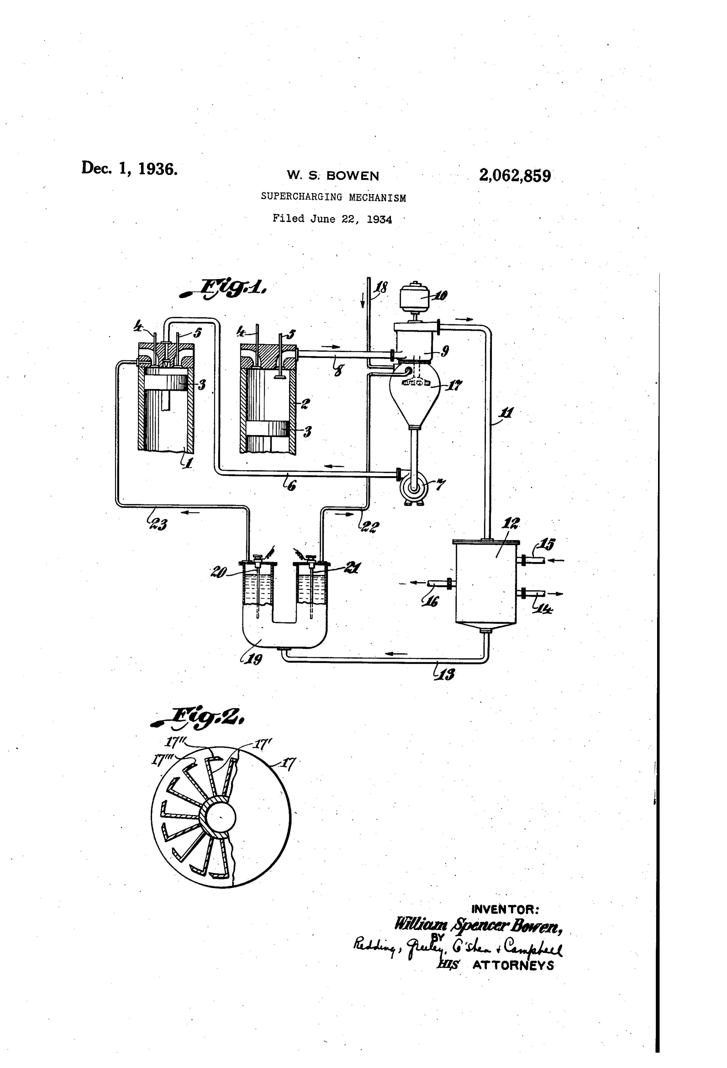
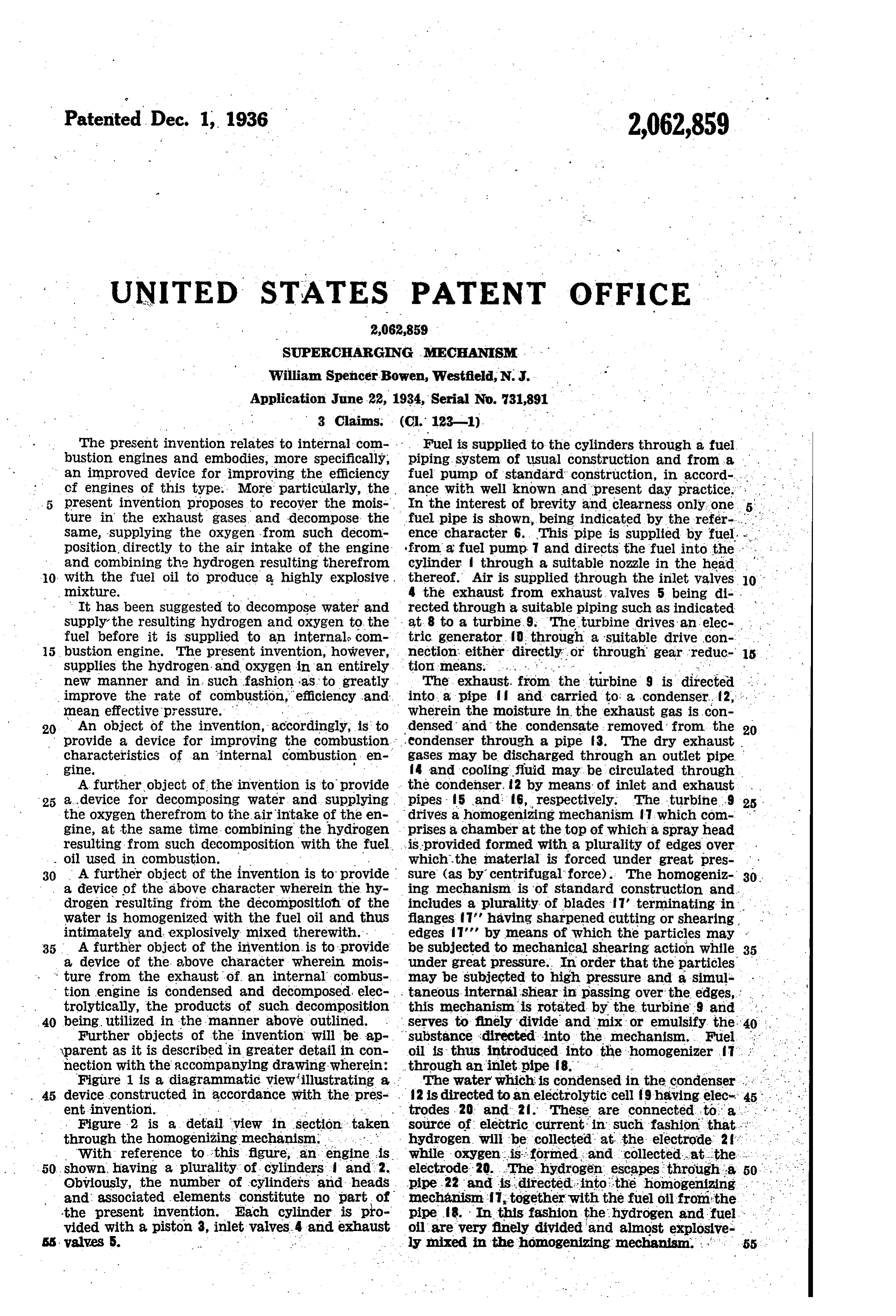
The present invention relates to internal com Fuel is supplied to the cylinders through a fuel bustion engines and embodies, more specifically, piping. System of usual construction and from a . an improved device for improving the efficiency : cf engines of this type. More particularly, the fuel pump of standard construction, in accord-... . . ance with well known and present day practice. . .
5 present invention proposes to recover the mois In the interest of brevity and clearness only one 5: . ture in the exhaust gases, and decompose the fuel pipe is shown, being indicated by the refer-.... . . . Same, supplying the oxygen from such decom ence character 6. This pipe is supplied by fuel. ... position, directly to the air intake of the engine from a fuel pump 7 and directs the fuel into the and combining the hydrogen resulting therefrom cylinder f through a suitable nozzle in the head 0 with the fuel oil to produce a highly explosive, thereof. Air is supplied through the inlet valves 10 mixture. . . w 4 the exhaust from exhaust valves 5 being di-, It has been suggested to decompose water and rected through a suitable piping such as indicated supply the resulting hydrogen and oxygen to the at 8 to a turbine.9. The turbine drives an elec- . fuel before it is supplied to an internals com tric generator, ?o through a suitable drive con 15 bustion engine. The present invention, however, nection either directly, or through gear reduc 15 supplies the hydrogen- and oxygen in an entirely. tion means. . . . . . ;
new manner and in such fashion as to greatly . The exhaust. from the turbine s is directed improve the rate of combustion, efficiency and into a pipe? and carried to a condenser. 2, , , mean effective pressure. . . .. . . . wherein the moisture in the exhaust gas is con 20. An object of the invention, accordingly, is to densed and the condensate removed from the 20 provide a device for improving the combustion. eondenser through a pipe f3. The dry exhaust . characteristics of an internal combustion en gases gine. m may be discharged through an outlet pipe 4 and cooling fluid may be circulated through
A further object of the invention is to provide the condenser, 2 by means of inlet and exhaust 25 a...device for decomposing water and supplying . pipes 5 and 6, respectively. The turbine.9 25 - the oxygen therefrom to the air intake of the en drives a homogenizing mechanism T which com gine, at the same time combining the hydrogen prises a chamber at the top of which a spray head resulting from such decomposition with the fuel. ...isprovided formed with a plurality of edges over oil used in combustion.
30 A further object of the invention is to provide surewhich the material is forced under great pres (as by centrifugal force). The homogeniz 30.
a device of the above character wherein the hy ing mechanism is of standard construction and. drogen resulting from the decompositioh of the includes a plurality of blades 7 terminating in . . . water is homogenized with the fuel oil and thus flanges 7' having sharpened cutting or shearing intimately and explosively mixed therewith. edges 7' by means of which the particles may 35 A further object of the invention is to provide be subjected to mechanical shearing action while 35 a device of the above character wherein mois under great pressure. In order that the particles ture from the exhaust of an internal combus may be subjected to high pressure and a simul tion engine is condensed and decomposed elec taneous internal shear in passing over the edges, . trolytically, the products of such decomposition this mechanism is rotated by the turbine 9 and 40 being, utilized in the manner above outlined. serves to finely divide and mix or emulsify the Further objects of the invention will be ap substance directed into the mechanism. Fuel, yparent as it is described in greater detail in con oil is thus introduced into the homogenizer it nection with the accompanying drawing wherein: through an inlet pipe 8. . . .
Figure 1 is a diagrammatic view'illustrating a The water which is condensed in the condenser . . . . . 45 device constructed in accordance with the pres- . 2 is directed to an electrolytic cell 9 having elec-45. . ent invention. trodes. 20 and 2. These are connected to a . . . . Figure 2 is a detail view in section taken source of electric current in such fashion that..:”. through the homogenizing mechanism. ... hydrogen, will be collected at the electrode 2. with reference to this figure, an engine is. while oxygen is: formed and collected at the . . 50, shown, having a plurality of cylinders and 2. electrode 20. The hydrogen escapes through a Obviously, the number of cylinders and heads pipe .22 and is directed into the homogenizing . . . . . . . and associated elements constitute no part of mechanism T together with the fuel oil from the -the present invention. Each cylinder is pro pipes. In this fashion the hydrogen and fuel. . . . vided with a piston 3, inlet valves. 4 and exhaust oil are very finely divided and almost explosive SS. valves 5. -w . . . . . m ly mixed in the homogenizing mechanism...'. 55
Page 3
The oxygen which is formed and collected at thereto, means to condense the water vapor in the electrode 28 is directed through a pipe line the engine exhaust, electrolytic means to decom 23 and sucked directly into the air inlet stream pose the condensed water vapor, means to intro On the suction stroke of the engine. In this duce the oxygen resulting from the decomposi fashion, the atmosphere within the cylinder will tion into the air supplied to the engine, and be very rich in oxygen. As the hydrogen is sucked means to mix the hydrogen resulting from the into the homogenizer and passes therethrough decomposition with the fuel prior to the intro it is thoroughly emulsified with the fuel oil and duction thereof into the engine. Will remain in Suspension for a Sufficient time to 2. A fuel charging device for an internal com 10 enter the combustion chamber virtually as a bustion engine comprising means to supply fuel O single fluid. The fuel pump will compress the thereto, means to condense the water vapor in oil and entrained gas and force the same under the engine exhaust, electrolytic means to decom high pressure through a nozzle in the combus pose the condensed water vapor into hydrogen tion chamber where a sudden reduction of pres and Oxygen, means to introduce the oxygen result 15 sure tends to atomize the oil by the expansion of ing from the decomposition into the air supplied 5 the entrained gas. This effect would be in to the engine, means to mix and subject the parti creased by some heating of the mixture of the oil cles of fuel and hydrogen resulting from the decom and hydrogen under pressure. position of the condensed water vapor to internal As a result, the maximum temperature will shear under high pressure, and means to supply 20 tend to be lowered by keeping the specific heats the homogenized hydrogen and fuel to the engine 20 down, at the same time improving the rate of under pressure.
combustion, efficiency and the mean effective 3. The method of operating an internal com pressure. Obviously, the electric generator 10 bustion engine comprising condensing the mois may Supply the electric current for Operating the ture in the engine exhaust, decomposing the con 25 electrolytic cell 9. densed moisture into hydrogen and oxygen, in 25 While the invention has been described with troducing the oxygen of decomposition into the specific reference to the accompanying draw air Supplied to the engine, mixing the engine fuel ing, it is not to be limited, save as defined in the with the hydrogen produced by the decomposi appended claims. tion, and introducing the mixture of fuel and 30 I claim as my invention: hydrogen into the engine, 30 1. A fuel charging device for an internal com bustion engine comprising means to supply fuel WILLIAMSPENCER BowF.N.
Provenance
- Collection
- Cited prior art
- Original PDF
- patentimages.storage.googleapis.com →
- Filed
- 1934-06-22
- Pages
- 3
- Method
- pdftotext (the PDF's own text layer) + pdftoppm 300dpi page scans
- Source
- Google Patents bibliographic record
- Granted
- 1936-12-01
- Inventors
- Bowen William Spencer
- Transcribed from
- patentimages.storage.googleapis.com →