patent · US1234774
Oil-feed indicator.
31 July 1917
Page 1
Drawing sheet — no readable text.
Page 2
UNITED STATES PATENT OFFICE.
HENBY KocoUREK, oF c??????, IIIINOIs, ASSIGNOR TO SEWARWARSR see EponeFER CORPORATION, OF CHICAGO, ILLINOIs, A coRPoRATION OF
VRGSA
O-FEED INDICATOR.
1,28?,???. Specification of Letters Patent. Patented July 31, 1917. Application filed August 28, 1914, serial No. 858,747.
To all whom it may concern: - needle,
That 9, upon a properly graduated dial, 10, is, to maintain a given rate of flow
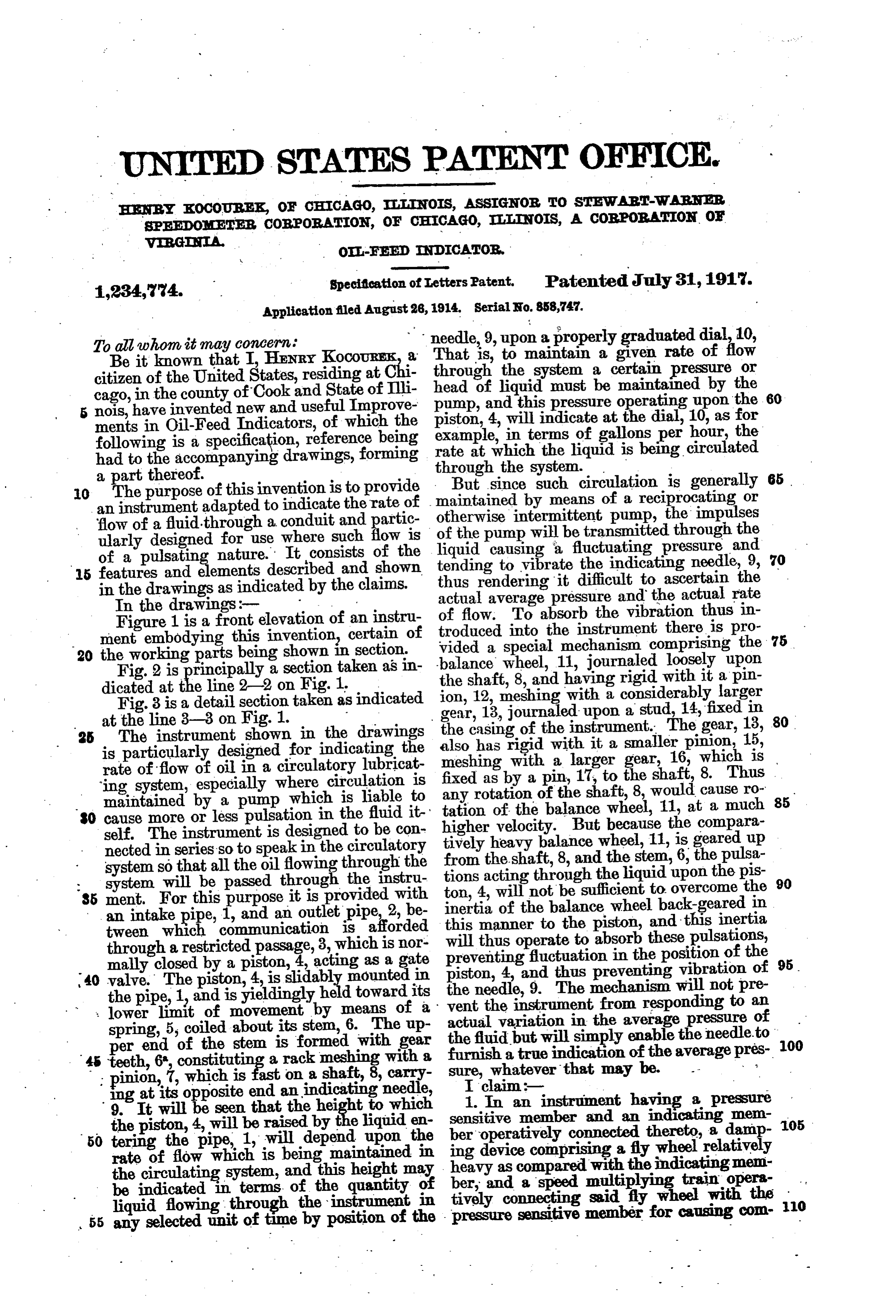
Be it known that I, HENRY KocouREk, a citizen of the United States, residing at Chi through the system a certain pressure or cago, in the county of Cook and State of Illi head of liquid must be maintained by the 5 nois, have invented new and useful Improve pump, and this pressure operating upon the 60 piston, 4, will indicate at the dial, 10, as for ments in Oil-Feed Indicators, of which the example, in terms of gallons per hour, the following is a specification, reference being had to the accompanying drawings, forming rate at which the liquid is being circulated a part thereof. through the system.
0. The purpose of this invention is to provide maintained But since such circulation is generally 65 an instrument adapted to indicate the rate of otherwise intermittent by means of a reciprocating or flow of a fluid-through a conduit and partic of the pump will be transmitted pump, the impulses ularly designed for use where such flow is liquid causing a fluctuating pressure through the of a pulsating nature. It consists of the tending to vibrate the indicating needle,and 15 features and elements described and shown thus rendering it difficult to ascertain the in the drawings as indicated by the claims. actual average pressure and the actual rate
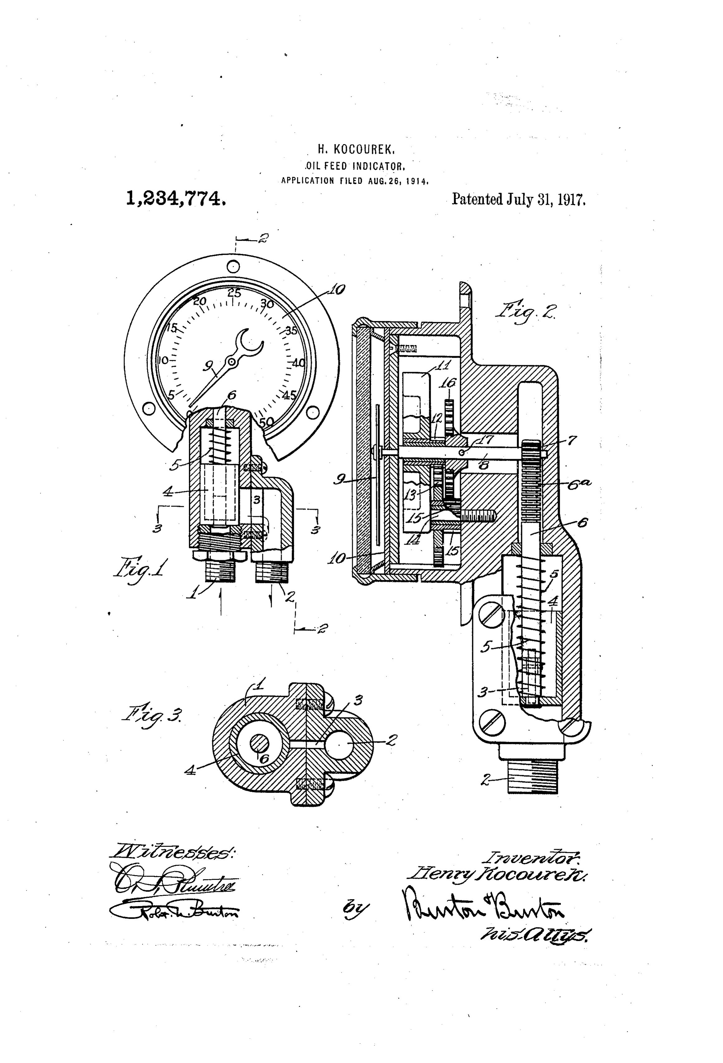
In the drawings:- - . of flow. To absorb the vibration thus in Figure 1 is a front elevation of an instru troduced into the instrument there is pro 75 ment embodying thi? invention, certain of vided a special 20 the working parts being shown in section balance mechanism comprising the wheel,
Fig. 2 is principally a section taken as in the shaft, 8, and having 11, journaled loosely upon dicated at ? line 2-2 on Fig. 1. rigid with it a pin ion, 12, meshing with a considerably
Fig. 3 is a detail section taken as indicated gear, 13, journaled upon a stud, 14, fixed larger at the line 3-3 on Fig. 1. - in 80 The instrument shown in the drawings the casing of the instrument. The gear, 13, is particularly designed for indicating the also has rigid with it a smaller pinion, 15, meshing with a larger gear, 16, which is rate of flow of oil in a circulatory lubricat fixed as by a pin, 17, to the shaft, 8. Thus ing system, especially where circulation is any rotation maintained by a pump which is liable to tation of theofbalance the shaft, 8, would cause ro 85 30 cause more or less pulsation in the fluid it higher velocity. But wheel, 11, at a much because the compara self. The instrument is designed to be con tively heavy balance wheel, 11, is geared up nected in series so to speakin the circulatory system so that all the oil flowing through the from the shaft, 8, and the stem, 6, the pulsa tions acting through the liquid upon the pis 90 system will be passed through the instru ton, 4, will not be sufficient to overcome the 85 ment. For this purpose it is provided with inertia of the balance wheel back-geared in an intake pipe, 1, and an outlet pipe, 2, be tween which communication is afforded this manner to the piston, and this inertia through a restricted passage, 3, which is nor will thus operate to absorb these pulsations, mally closed by a piston, 4, acting as a gate preventing fluctuation in the position of the 95 40 valve. The piston,4 is slidably mounted in the needle, 9. thus piston, 4, and
The preventing vibration of mechanism will not pre the pipe, 1, and is yieldingly held toward its vent the instrument from responding to an : lower limit of movement by means of a actual variation in the average pressure of spring, 5, coiled about its stem, 6. The up the fluid but will simply enable the needle.to per end of the stem is formed with gear a true indication of the average pres 100 45 teeth, 6, constituting a rack meshing with a furnish ; ing pinion, at its7, opposite which is end fastanonindicating carry sure, a shaft, 8,needle, whatever that may be.
9. It will be seen that the height to which 1.In anmember instrument having a pressure the piston, 4, will be raised by the liquid en sensitive and an indicatingir mem T05 50 tering the pipe, 1, will depend upon the ber operatively connected thereto, a damp rate of flow which is being maintained in ing device comprising a fly wheel relatively the circulating system, and this height may heavy as compared with the indicating mem ber, and a speed multiplying train opera be indicated in terms of the quantity of tively connecting said fly wheel with the O liquid flowing through the instrument in 55 any selected unit of time by position of the pressure sensitive member for causing con
Page 3
paratively rapid movement of said fly wheel a port for affording communication between during slow movement of the pressure sen them, a piston in the inlet conduit posi 25 sitive member and its connected indicating tioned to control said port, yielding means eaS. tending to hold said piston in position to 2. An instrument for the purpose indi close the port in opposition to the pressure cated comprising an inlet conduit, an outlet, of incoming fluid, a rack gear connected to a port for affording communication between the piston, a pinion journaled to mesh with 30 them, a piston in the inlet conduit positioned said rack, a shaft for said pinion, a gradu to control said port, yielding means tend ated dial, and an indicating needle fixed to 0 ing to hold said piston in position to close said shaft in position to traverse the dial to the port in opposition to the pressure of in . gether with a fly wheel loosely mounted on coming fluid, and relatively light indicat the shaft, and speed-multiplying gearing 35 ing means operatively connected to said pis from the shaft to the fly wheel whereby the ton, together with a relatively heavy fly inertia of said wheel is adapted to resist 15 wheel, and speed multiplying gearing con acceleration of the shaft. necting it with the piston adapted to cause. In testimony whereof I have hereunto set comparatively rapid movement of said fly my hand at Chicago, Illinois, this 24th day 40 wheel during slow movement of the piston of August, 1914.
and its connected indicating means where 20 by said fly wheel serves as a damper for the HENRY KOCOUREK. piston and said indicating means. Witnesses:
3. An instrument for the purpose indi RoBT. N. BURTON, cated comprising an inlet conduit, an outlet, EDNA M. MacINTOSH.
Provenance
- Collection
- Cited prior art
- Original PDF
- patentimages.storage.googleapis.com →
- Filed
- 1914-08-26
- Pages
- 3
- Method
- pdftotext (the PDF's own text layer) + pdftoppm 300dpi page scans
- Source
- Google Patents bibliographic record
- Granted
- 1917-07-31
- Inventors
- Henry Kocourek; Stewart Warner Speedometer Corp
- Transcribed from
- patentimages.storage.googleapis.com →