patent · US5507946
Apparatus for wastewater treatment
16 April 1996
Page 1 — bibliographic record
United States Patent (19) 11 Patent Number: 5,507.946 Stearns 45) Date of Patent: Apr. 16, 1996 54 APPARATUS FOR WASTEWATER 4,094,783 6/1978 Jackson ................................... 210/703 TREATMENT 4,168,228 9/1979 Mallatt et al. .......................... 210/703
(75 Inventor: Donald M. Stearns, Cocoa, Fla.
Primary Examiner Thomas Wyse 73 Assignee: PEC Research, Inc., Sharpes, Fla. Attorney, Agent, or Firm-Antonelli, Terry, Stout & Kraus (21) Appl. No. 587,043 57) ABSTRACT (22 Filed: Sep. 24, 1990 -
A process for treating wastewater containing insoluble solid
Related U.S. Application Data waste material and soluble solid waste material including the following series of steps: (1) controlling the oxygen content 62) Division of Ser. No. 301,463, Jan. 26, 1989, Pat. No. of the wastewater to a level at which growth of anaerobic 4,976,863. bacteria is substantially eliminated, (2) separating the (51) Int. Cl. ................ C02F 3/30 insoluble solid waste material from the wastewater, (3) 52 U.S. Cl. .................. ... 210/202; 210/221.2 treating the soluble solid material in the wastewater with a 58 Field of Search ..................................... 210608, 703, predetermined amount of aerobic bacteria, and (4) reducing 210/704, 769, 96.1, 202, 205, 218, 220, the amount of aerobic bacteria in the wastewater. The 221.2 insoluble solid waste material separated from the wastewater can be burned to produce electrical energy. Apparatus for (56) References Cited carrying out the process are also disclosed.
3,622,508 11/1971 Komline .................................. 210,608 3,803,806 4/1974 Konline, Sr. ........................... 210,769 9 Claims, 5 Drawing Sheets
AAAAAS Sanya
Page 2
Drawing sheet — no readable text.
Page 3
Drawing sheet — no readable text.
Page 4
Drawing sheet — no readable text.
Page 5
Drawing sheet — no readable text.
Page 6
Drawing sheet — no readable text.
Page 7
APPARATUS FOR WASTEWATER phase. The lower the concentration of dissolved oxygen in TREATMENT the liquid phase, the slower the growth rate of the aerobic bacteria. Increases in the retention time in the collection and
This is a division of application Ser. No. 07/301,463, transmission systems associated with the treatment plant filed Jan. 26, 1989, now U.S. Pat. No. 4,976,863. 5 affects the condition of the wastewater received and the treatment process used. Without the wastewater being exposed to air contact, the loss of dissolved oxygen con
BACKGROUND OF THE INVENTION centration can result in wastewater being received at the treatment plant in a condition that can adversely affect the
For the entire history of the treatment of waste products normally used aerobic process.
produced by the bodies of animals or mankind, a naturally 10 Since a means for effectively controlling dissolved oxy occurring process has been the basis for the treatment of gen levels to a sufficient level in the collection and trans carbon-based and other compounds that make up the body mission systems was not previously available, the final waste. The presence of several types of bacteria which are treatment process was limited to the continuation of the included in the waste body products from all animals and 15 process provided by natural occurrence. Only the selection mankind have provided the means of treatment by either of of the type of aerobic or anaerobic process to continue the two biological processes. One class of naturally occurring biological treatment could be utilized in wastewater treat bacteria utilizes any dissolved oxygen in the water phase of ment plants.
the waste to oxidize the waste products with the resulting Three types of aerobic biological treatment processes are production of water, carbon dioxide and other oxide prod 20 the most commonly found in wastewater treatment plants: ucts. If the waste liquid phase does not contain dissolved the extended aeration process, the contact stabilization pro oxygen, the second class of naturally occurring bacteria is cess and the complete mix process. All three processes able to act on the carbon-based and other compounds with utilize aeration devices to increase the dissolved oxygen the resulting production of hydrogen sulfide, methane and concentration of the liquid phase of the wastewater and the other complex organic compounds. return of wastewater solids with high concentrations of 25 bacteria growth. The main differences between the three
The general classification for the bacteria that require dissolved oxygen in the liquid phase of the waste-water for processes in the is the amount of retention time of the wastewater aeration Zones of the treatment process, the amount of growth is aerobic bacteria. Due to the very low solubility of return of wastewater solids with high bacterial growth and oxygen in water, air must be in contact with the wastewater on a frequent cycle basis in order to resupply the dissolved 30 of after the aeration process.solids the amount of wastewater that remain to be disposed
The problem of disposal of the oxygen in the wastewater. The second naturally occurring excess wastewater solids or sludge resulting from any of the general class of bacteria is anaerobic bacteria which is based three biological treatment processes has become a major on the requirement that there cannot be any amount of threat to not only mankind, but also to the entire planet by dissolved oxygen in the wastewater for its growth to occur. destruction of the water supply necessary for both animal As the by-products produced by the aerobic bacteria 35 and human life. The amount of sludge generated by the three growth in wastewater do not present a danger or provide an different biological processes is generally in the same ratio unacceptable secondary problem to mankind, it has in as the amount of retention time utilized in the aeration zones almost all cases become the primary process for wastewater of the treatment process. For all three of the processes used, Secondary treatment of sludge by either aerobic or anaerobic treatment. The planned use of the second naturally available bacterial action is required. The greater the amounts of bacteria, anaerobic, has been confined to situations that lend sludge developed by the short retention times in the aeration themselves to the use of closed tanks or underground con tainers. The by-products produced by the action of the Zones of the treatment process, the greater the production of anaerobic bacteria result in major problems in the area of controlled sludge hazardous disposal.
that will require secondary treatment and explosion hazard, corrosion problems, offensive odor and toxic reaction to mankind. The past and current processes for 45 in The
development of the centrifugal oxygenator described patent application Ser. No. 07/109,192 filed Oct. 16, the treatment of wastewater are based on the use of the 1987 (which is a continuation of U.S. patent application Ser. naturally occurring bacteria in either the aerobic bacterial cycle or the anaerobic bacterial cycle with the design of the No. 06/799,104 filed Nov. 18, 1985, now abandoned) and pending PCT application PCT/US86/02542, the contents of treatment system being controlled by the ability to provide each of which are incorporated herein by reference, now the most efficient environment for either type of bacterial 50 provides the means to control the dissolved oxygen levels in growth. This design factor has to also have as a major wastewater collection and transmission systems which, in consideration the disposal of the by-products of the bacterial turn, allows the control of the naturally occurring bacterial act1Ol. growth. The centrifugal oxygenator has proven by certified The treatment of wastewater does not begin at the treat testing that it has the ability to provide oxygen transfer rates ment plant and this factor has become a major problem as 55 of 40% in liquid levels of only two feet to as high as 98% the size of collection and transmission systems have been at liquid levels of over twenty feet. Unlike prior aeration increased to minimize the number of treatment plants devices, the centrifugal oxygenator provides complete con required. The action of the naturally occurring bacteria trol of the air or gas flow rate from 0% to the maximum begins at the point of introduction of the body waste capacity of the unit size. The centrifugal oxygenator can products into a water carrier. The growth of the aerobic 60 operate on a stop/start basis without any clogging of the air bacteria is normally the first action as most wastewater or gas flow passages and also provides a high velocity liquid phases will contain some amount of dissolved oxy directionalized mixing and solid suspension hydraulic flow gen. If the dissolved oxygen level is not maintained at some from the unit.
positive value, the growth of the aerobic bacteria will stop SUMMARY OF THE INVENTION and be replaced by the growth of dormant anaerobic bacte 65 ria. The action of the aerobic bacteria is a self-limiting factor The present invention provides a process for treating based on the availability of dissolved oxygen in the liquid wastewater containing insoluble solid waste material and
Page 8
soluble solid waste material comprising the following series the decrease in the density of the wastewater solid by its of steps: controlling the oxygen content of the wastewater to attachment to the low density fiber. These actions greatly a level at which growth of anaerobic bacteria is substantially increase the separation efficiency of the flotation process. eliminated, separating the insoluble solid waste material The primary step for the separation of the wastewater from the wastewater, treating the soluble solid material in solids from its liquid carrier is a two-stage pressurized air the wastewater with a predetermined amount of aerobic flotation system using the addition of a fiber slurry prepared bacteria and reducing the amount of aerobic bacteria in the from waste paper material to increase the physical separa wastewater, and also provides an apparatus for its practice. tion efficiency of the flotation process. The second step The present invention combines the purification of waste applies batch/continuous aerobic biological action for the water with the disposal of waste paper materials for the 10 treatment of soluble matter. The third step uses high liquid generation of electrical power. The process does not rely on level, high efficiency solids removal settling to remove either aerobic or anaerobic bacteria for chemical modifica solids not removed in the primary step. The final step in the tion of the non-soluble wastewater solids. Biological treat wastewater treatment process applies contact columns with ment is confined to the soluble material in the wastewater. coal and paper fiber media for solids removal and bacterial The process utilizes control of dissolved oxygen levels in the 15 reduction. The soluble material in the wastewater is treated wastewater collection, transmission and treatment system in by controlled aerobic biological action in batch/continuous place of the currently applied uncontrollable addition of air variable operating level aeration tanks with the controlled or other oxidizing chemicals. Previous means for addition of addition of return activated sludge which has a known air to wastewater were limited in their ability to operate concentration of dissolved oxygen and a known concentra under the conditions of start/stop or variable gas rate 20 tion of aerobic bacteria. The level of dissolved oxygen in the requirements needed for the control of dissolved oxygen batch/continuous aeration tanks can be controlled at mini levels. The use of centrifugal oxygenators provides the mum required levels for the treatment of the soluble material means of control of the dissolved oxygen in wetwells, in order to minimize the amount of bacterial growth on the pipelines and throughout the wastewater treatment plant, wastewater solids not removed by the pressurized air sepa thus providing the means for control or elimination of the 25 ration phase of the treatment process. The high efficiency growth of anaerobic bacteria and minimizing the growth of settling tanks (clarifiers) obtain their increased efficiency as aerobic bacteria. With the placement of centrifugal oxygen compared with current designs by a substantial increase in ators in gravity collection manholes and pump station the liquid level which is allowable by the removal of most wetwells of adequate size to provide sufficient retention time of the wastewater solids in the primary stage, the control of for oxygen transfer, and as sidestream circulators in force 30 bacterial concentrations and the control of the dissolved main transmission pipelines using pure oxygen gas feed to oxygen levels in the feed to the settling tanks. The contact the centrifugal oxygenator, control of dissolved oxygen columns act as a final removal stage for all wastewater solids levels is possible with the result that the control of both and also the reduction in bacteria in the effluent of the anaerobic and aerobic bacterial development is now pos treatment process using pre-contact column chlorination. sible. 35 The contact columns contain single use (one operating The efficiency of both physical separation of the waste cycle) mixed media of coal particles and paper fiber. In water solids and the recovery of the energy value of the addition to the mixed media, a high concentration of chlo solids are a function of the elimination of the growth of rine or similar-acting chemical is maintained in the contact anaerobic bacteria in the collection and transmission sys columns for high efficiency bacteria reduction. tems and the minimizing of the growth of aerobic bacteria by 40 The wastewater solids are combined with the coal and the maintenance of minimum levels of dissolved oxygen in paper fiber materials and thereafter used as a fuel for the the collection and transmission portions of wastewater sys energy recovery power generation section of the treatment tems. Wastewater transmission systems can now be designed plant. The process utilizes an internal reuse effluent system on either a constant rate or constant pressure basis using the to supply cooling water to the condenser of the power plant control of dissolved oxygen in storage type wetwells in 45 system and other needs in the process for media preparation, primary and repump stations and pipeline injection of pure transfer and energy recovery. An internal reuse storage and oxygen. Either of these designs will greatly reduce the chlorine contact tank equipped with a centrifugal oxygenator storage requirement at the treatment plant necessary for the is used to remove any excess chlorine from the reuse effluent constant rate operation of the plant process. by air stripping using the fine bubble dispersion and With the means for controlling the dissolved oxygen 50 increased oxygen levels which can be provided by the levels, which in turn minimizes the bacterial growth, and the centrifugal oxygenator. After internal reuse, the effluent is additional means of providing the constant flow rates in the treated for any needed adjustment in the dissolved oxygen wastewater treatment process, two additional problems must concentration by use of centrifugal oxygenators with be solved to provide high efficiency separation by air flota enriched or pure oxygen supplied in either a liquid or gas tion. The control of the raise rate of the air bubble must be 55 phase from bulk storage tanks or cylinders. All wastewater maintained as close as possible to the physical limitations solids that are removed and the fiber material and coal added imposed by the difference in specific gravity of the gas and for the operation of the process of the present invention are liquid phases. This is accomplished by dispersion of the gas mixed with the additional coal and shredded paper waste and phase into very small size gas particles and the use of used as fuel for the power generating system incorporated in positive gas pressure above the surface of the liquid phase. 60 the process design, thus completely eliminating the need for To further increase the separation efficiency, fibrous material disposal or additional treatment of the partially treated is contacted with the wastewater solids prior to introduction wastewater solids, thus producing a sludge-free process. into the pressurized separation column. The low density The process reduces the requirement for the return of fibrous material attachment to the wastewater solids pro activated sludge by an average factor of ten, thus greatly vides assistance in the flotation separation in two ways. The 65 reducing the internal flow requirement of the treatment primary assistance is the high degree of attachment of the air plant. The internal flow is also reduced by the elimination of bubble to the irregular surface of the fiber, and the second is the recycle wash water needed for many type of filters used
Page 9
S 6 for final effluent quality control. The process provides a bacteria is minimized. The oxygen content is controlled by superior effluent quality by the use of a non-backwash single use of, inter alia, centrifugal oxygenators, of the type use (one operating cycle) high efficiency dual mixed media described in U.S. patent application Ser. No. 07/109,192 and of solids and fiber in the contact columns for solids removal PCT application No. PCT/US86/02542. and bacterial reduction in place of tertiary filters or similar The level of dissolved oxygen needed in both the collec types of solids removal devices that require backwash water tion and transmission system is a function of the initial for removal of the trapped solids. The use of a constant concentration of both the aerobic bacteria and the retention pressure and/or a constant rate design system in the collec time required before additional oxygen can be added to the tion and transmission sections of the wastewater system can wastewater. For example, for low levels of aerobic bacteria provide an effective and low-cost reduction in the wastewa O and low retention times, dissolved oxygen levels of from 0.1 ter storage requirement and the treatment needed for the to 0.3 ppm could be sufficient to maintain a positive level of operation at a constant rate. In order to provide control of dissolved oxygen throughout the-complete retention time dissolved oxygen levels in the collection and transmission until additional oxygen could be added. In other systems, the systems, pump station wetwells must be increased in size as concentration of aerobic bacteria could be naturally higher compared to current design practice. By increasing the pump 15 caused by water with high levels of dissolved oxygen. Such station wetwell size above that needed for dissolved oxygen systems, with longer retention times until additional oxygen control, storage capacity for either the constant pressure or could be added, would require dissolved oxygen levels of constant rate transmission system can be obtained at very 2.0 to 3.0 ppm to store sufficient oxygen in the liquid phase small increases in initial cost. to prevent the complete destruction of the aerobic bacteria 20 and to prevent the growth of anaerobic bacteria until addi
BRIEF DESCRIPTION OF THE DRAWINGS tional oxygen could be added.
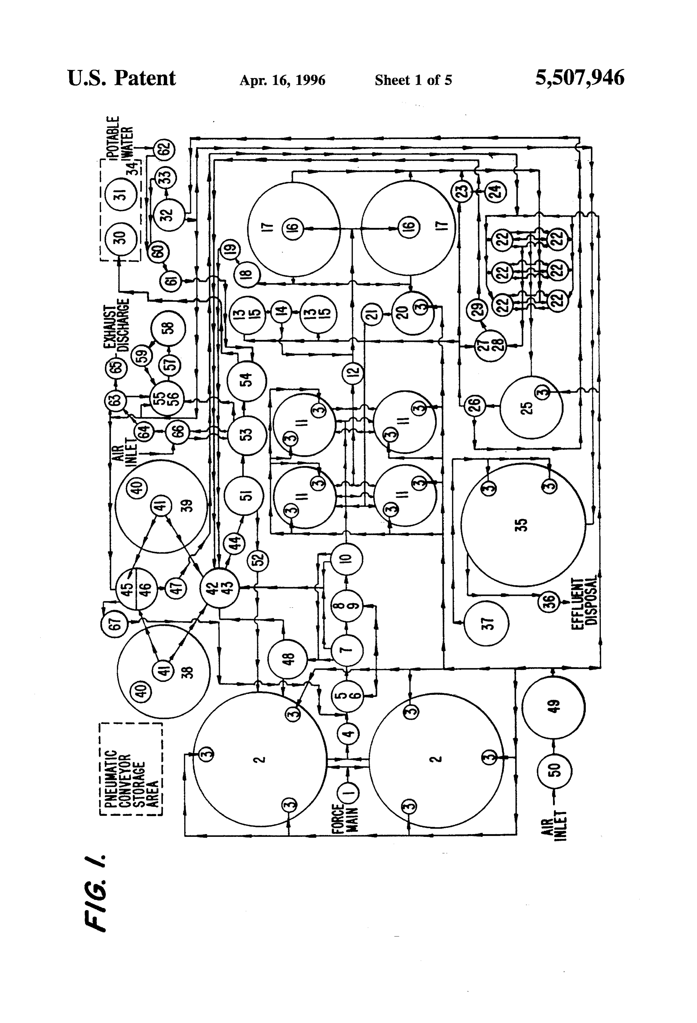
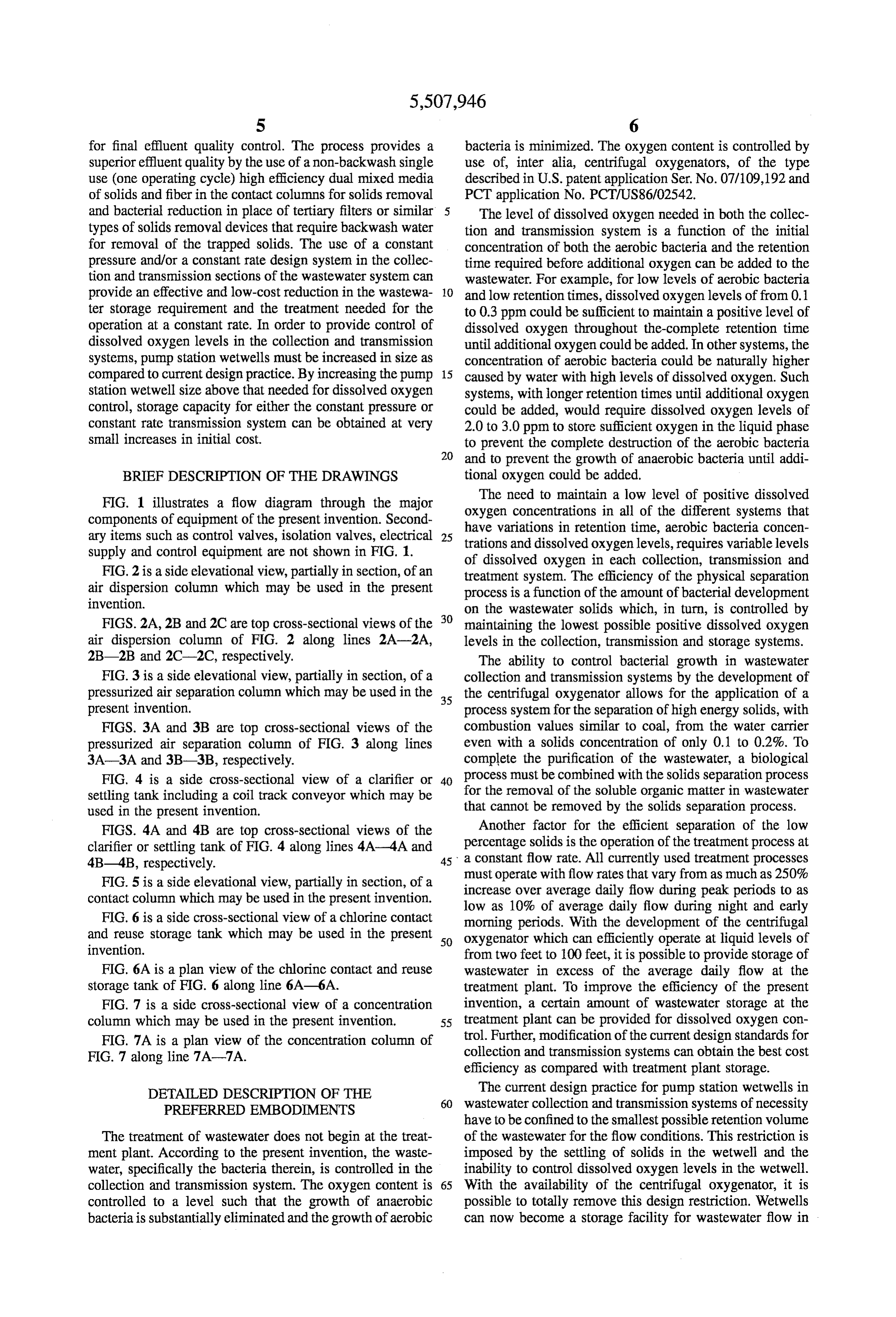
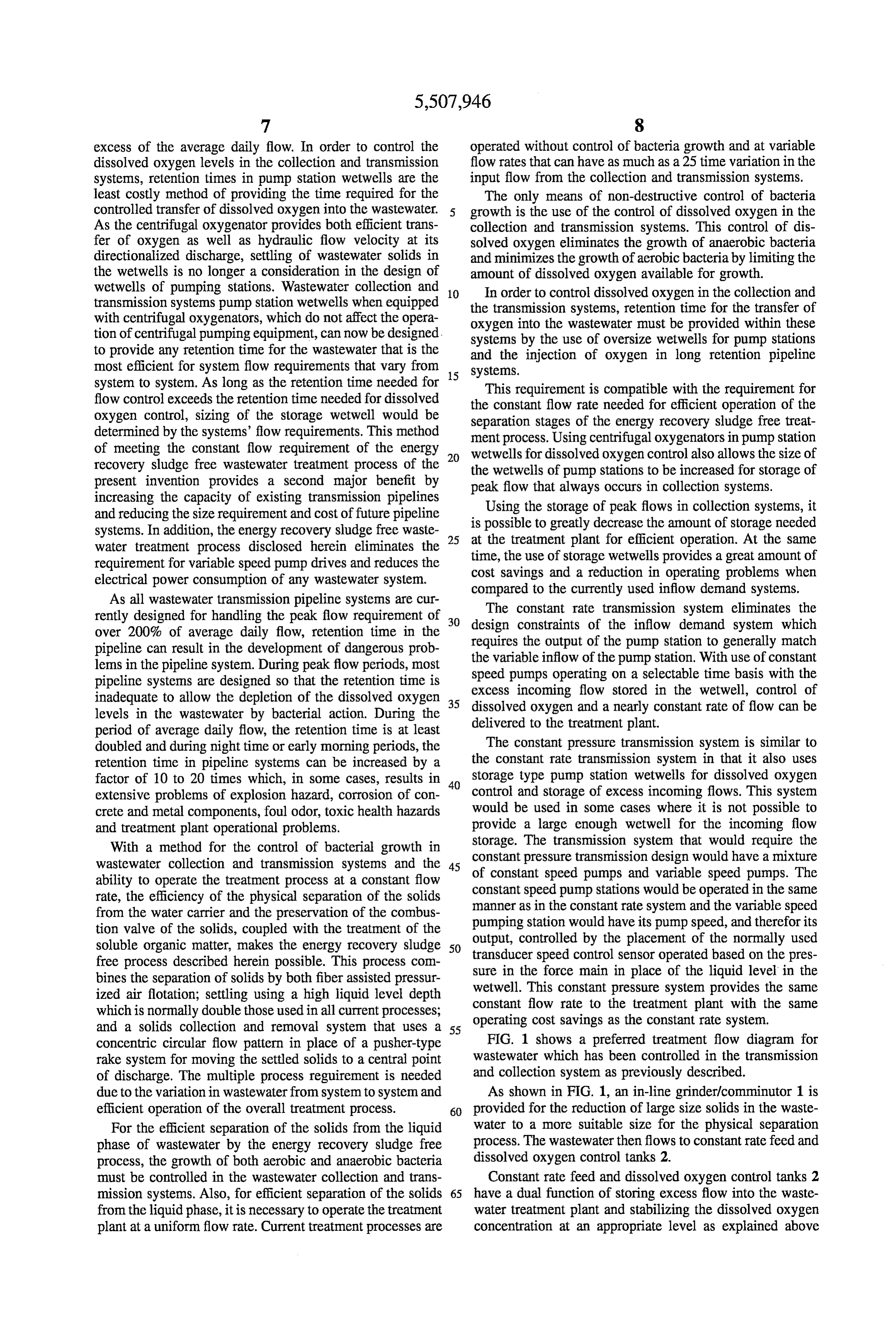
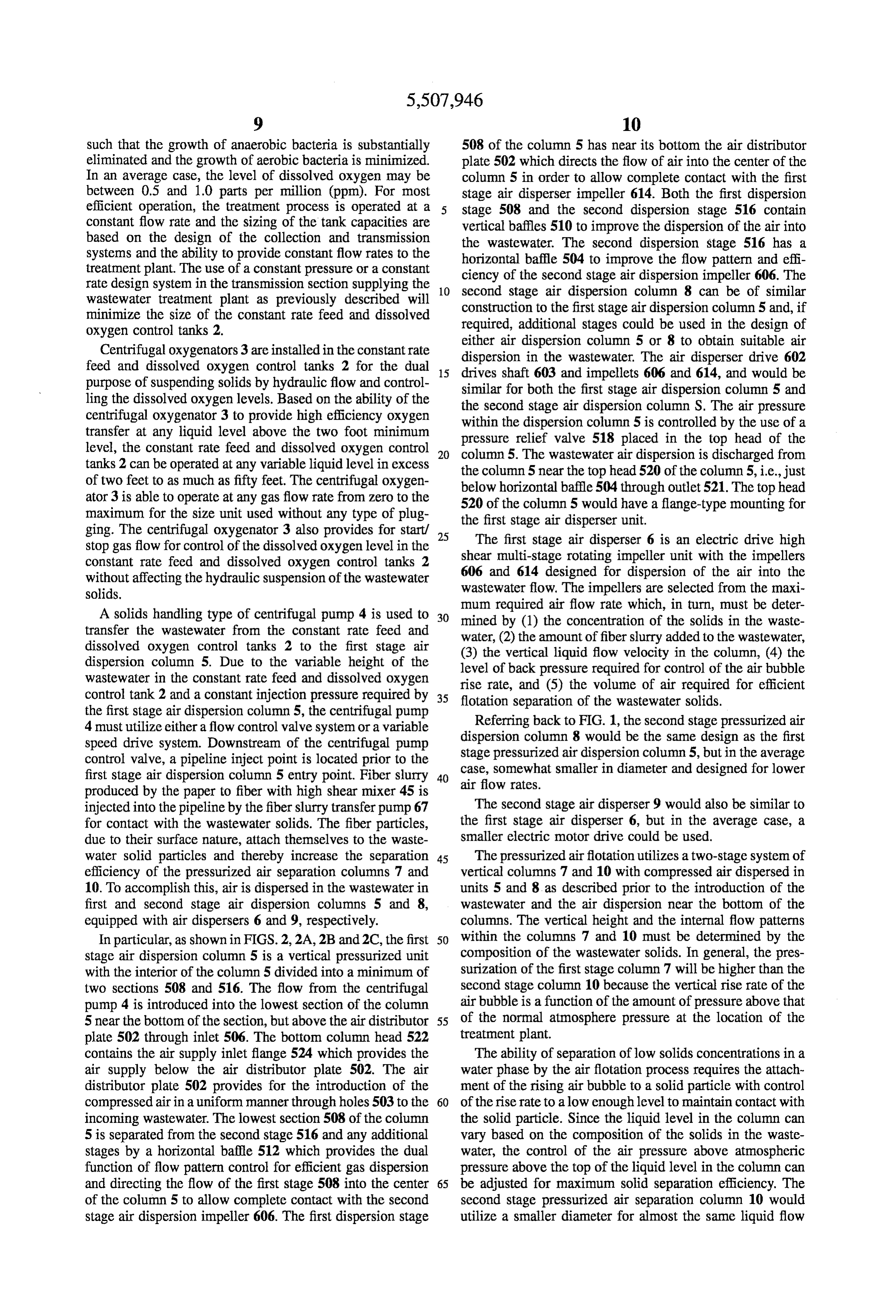
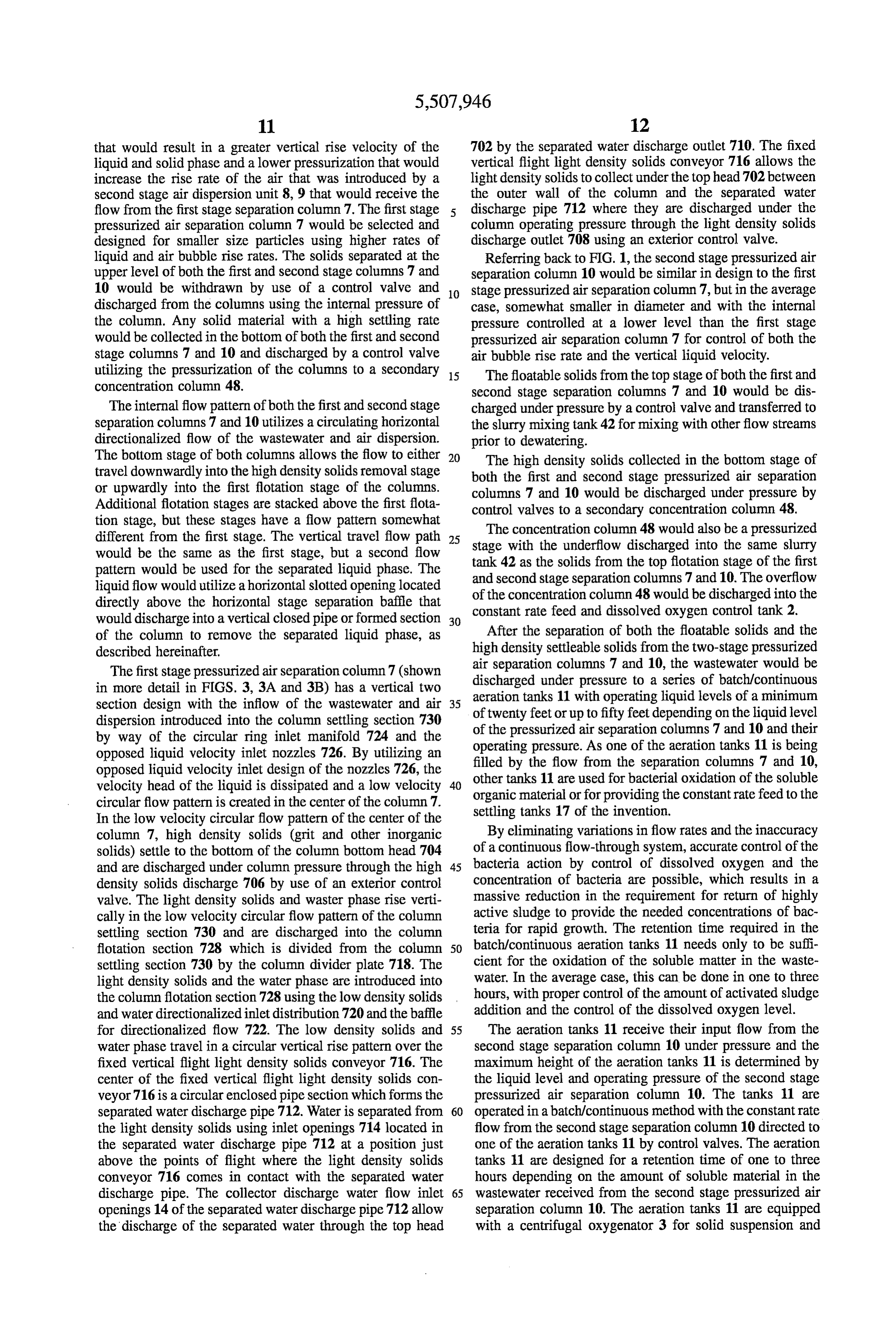
FIG. 1 illustrates a flow diagram through the major The need to maintain a low level of positive dissolved components of equipment of the present invention. Second oxygen concentrations in all of the different systems that have variations ary items such as control valves, isolation valves, electrical 25 trations and dissolvedin retention time, aerobic bacteria concen supply and control equipment are not shown in FIG. 1. oxygen levels, requires variable levels of dissolved oxygen in each collection, transmission and
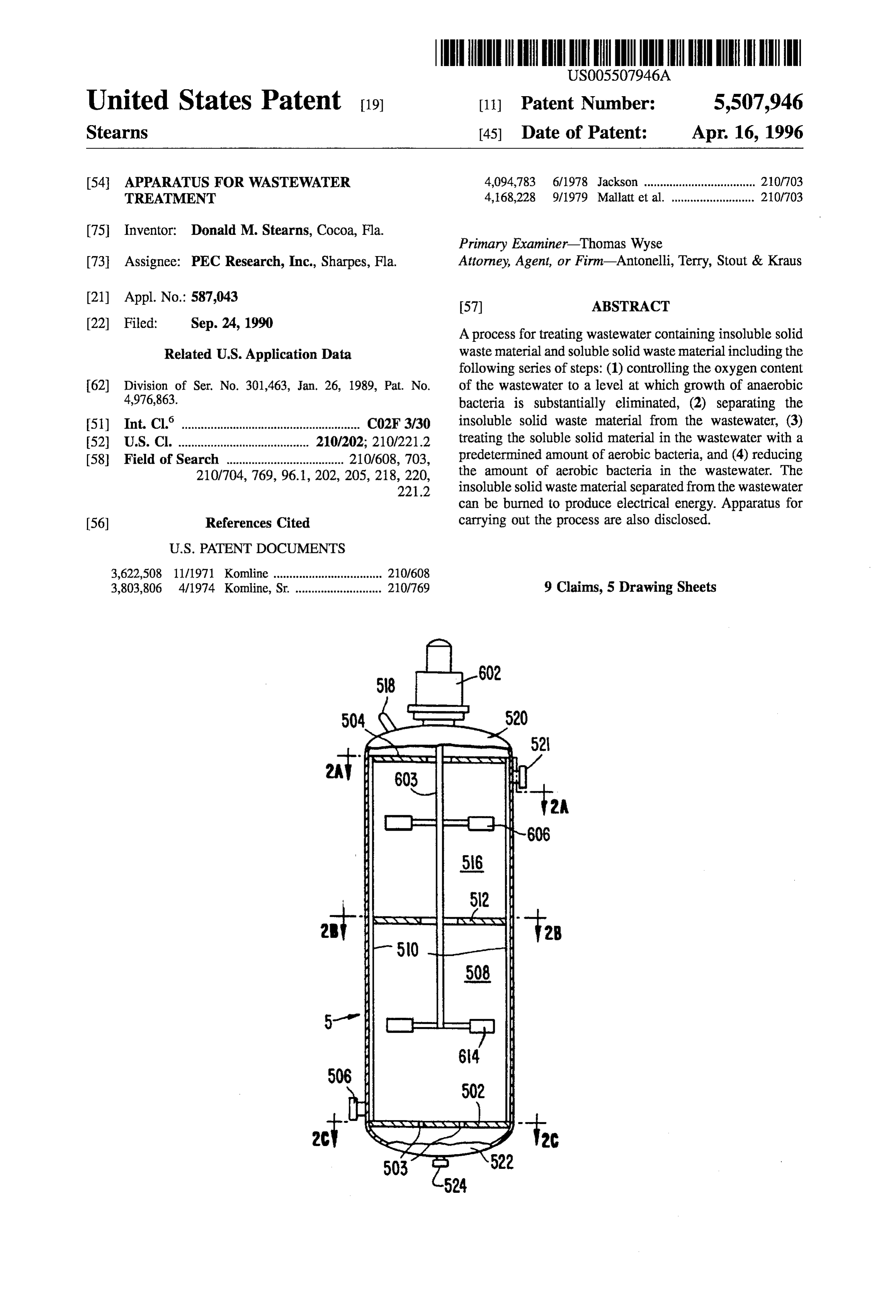
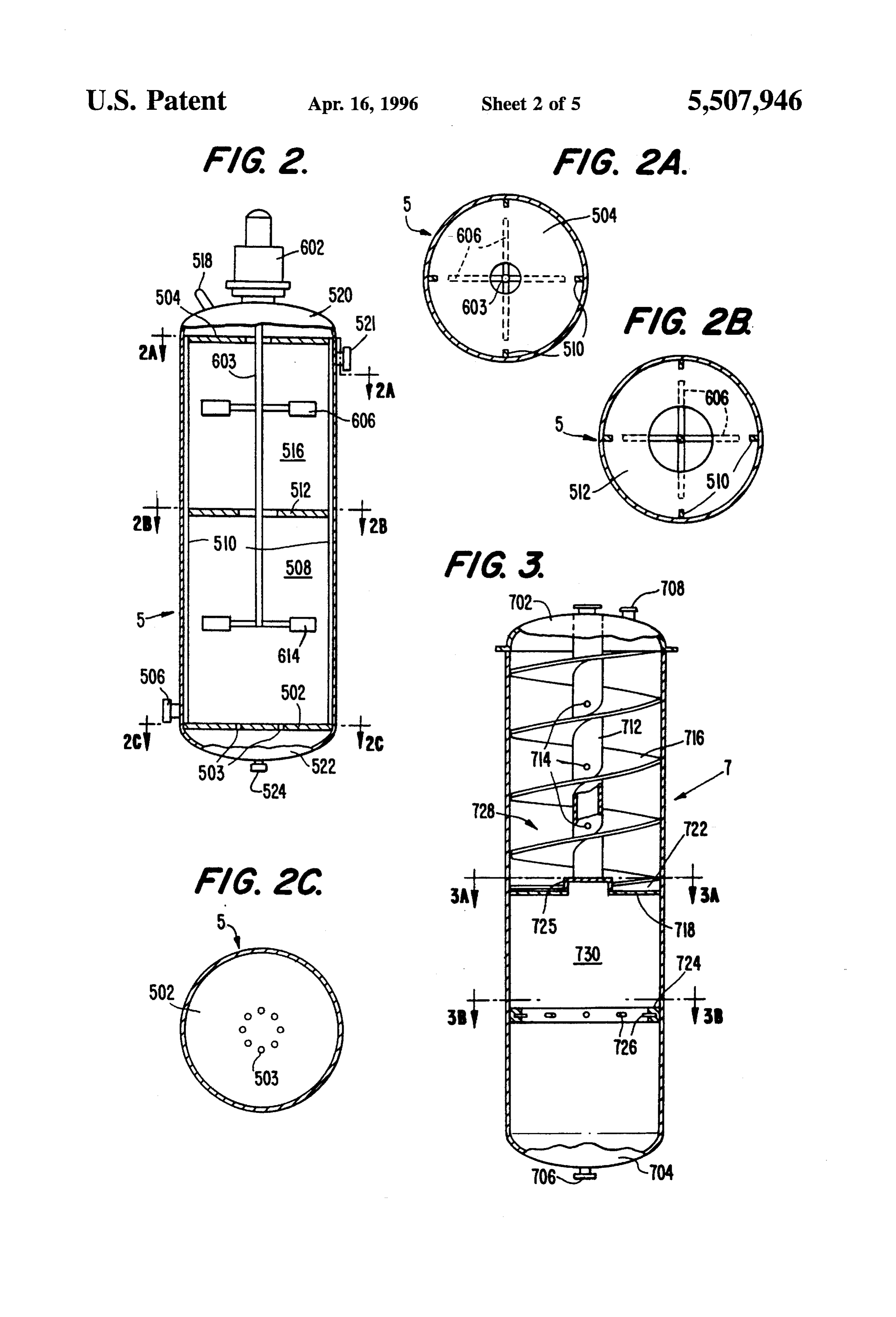
FIG. 2 is a side elevational view, partially in section, of an treatment system. The efficiency of the physical separation air dispersion column which may be used in the present process is a function of the amount of bacterial development invention. on the wastewater solids which, in turn, is controlled by
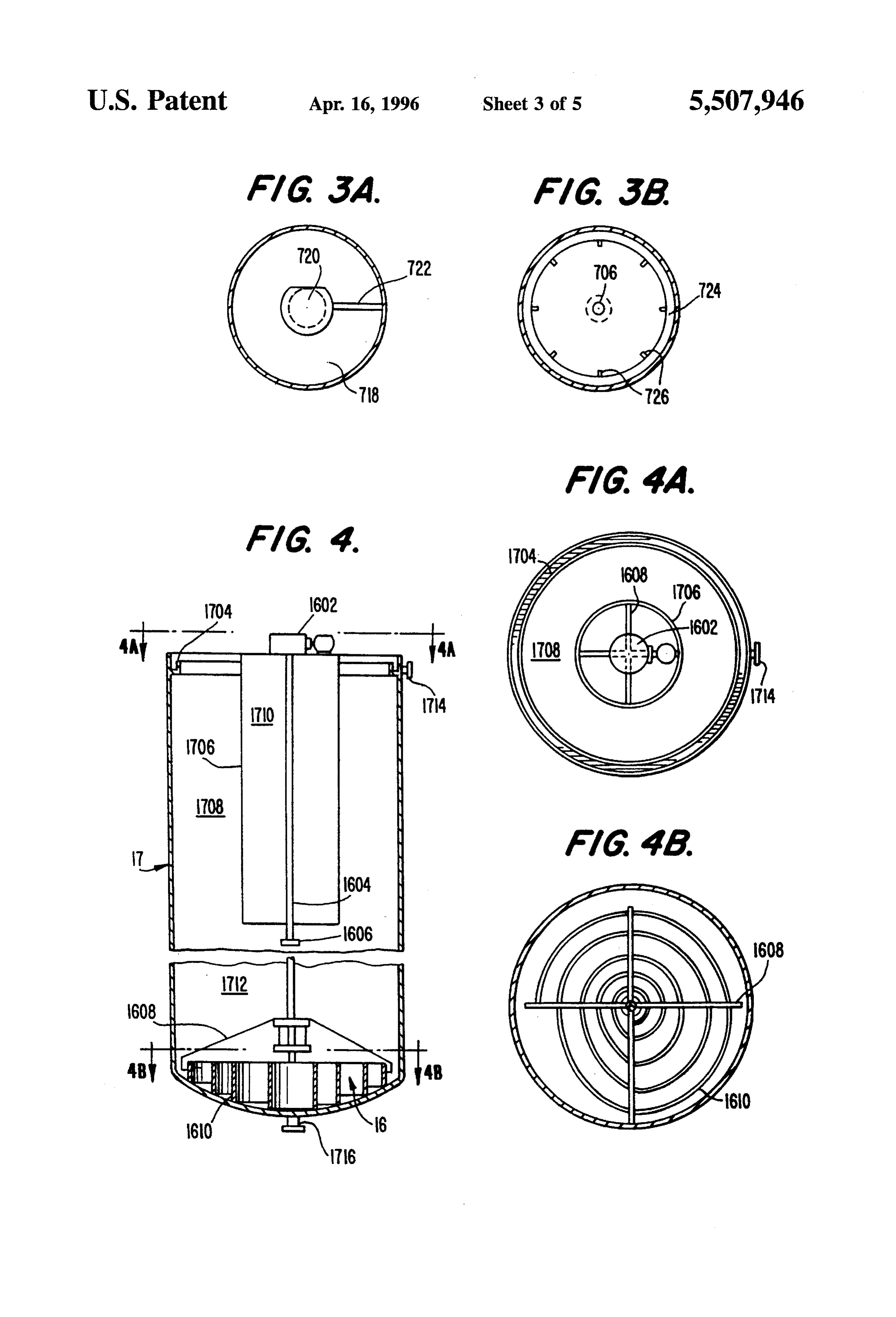
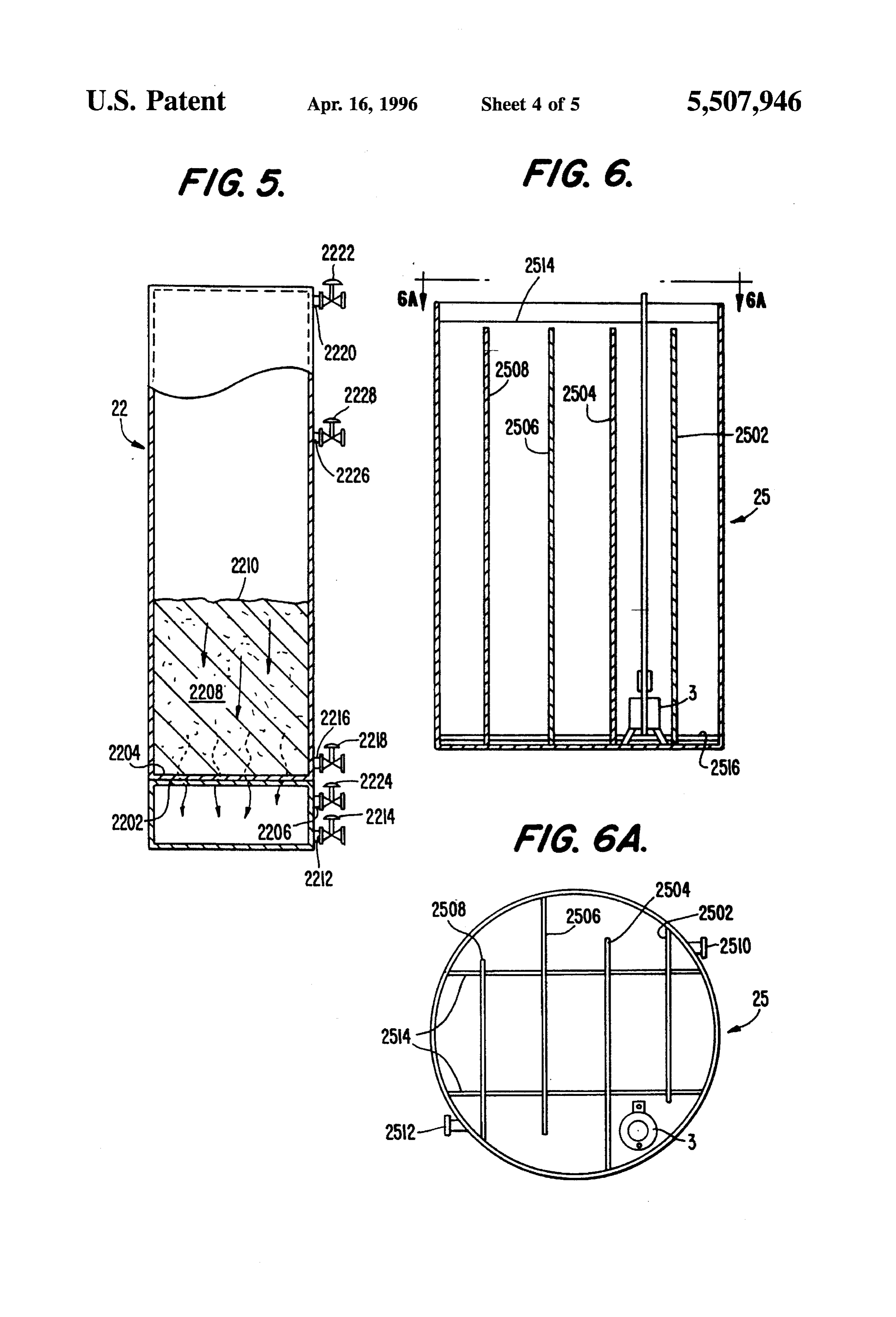
FIGS. 2A, 2B and 2C are top cross-sectional views of the maintaining the lowest possible positive dissolved oxygen air dispersion column of FIG. 2 along lines 2A-2A, levels in the collection, transmission and storage systems. 2B-2B and 2C-2C, respectively, The ability to control bacterial growth in wastewater FIG. 3 is a side elevational view, partially in section, of a collection and transmission systems by the development of pressurized air separation column which may be used in the 35 the centrifugal oxygenator allows for the application of a present invention. process system for the separation of high energy solids, with FIGS. 3A and 3B are top cross-sectional views of the combustion values similar to coal, from the water carrier pressurized air separation column of FIG. 3 along lines even with a solids concentration of only 0.1 to 0.2%. To 3A-3A and 3B-3B, respectively. complete the purification of the wastewater, a biological FIG. 4 is a side cross-sectional view of a clarifier or 40 process must be combined with the solids separation process settling tank including a coil track conveyor which may be for the removal of the soluble organic matter in wastewater used in the present invention. that cannot be removed by the solids separation process. FIGS. 4A and 4B are top cross-sectional views of the Another factor for the efficient separation of the low clarifier or settling tank of FIG. 4 along lines 4A-4A and percentage solids is the operation of the treatment process at 4B-4B, respectively. 45 a constant flow rate. All currently used treatment processes FIG. 5 is a side elevational view, partially in section, of a must operate with flow rates that vary from as much as 250% contact column which may be used in the present invention. increase over average daily flow during peak periods to as low as 10% of average daily flow during night and early
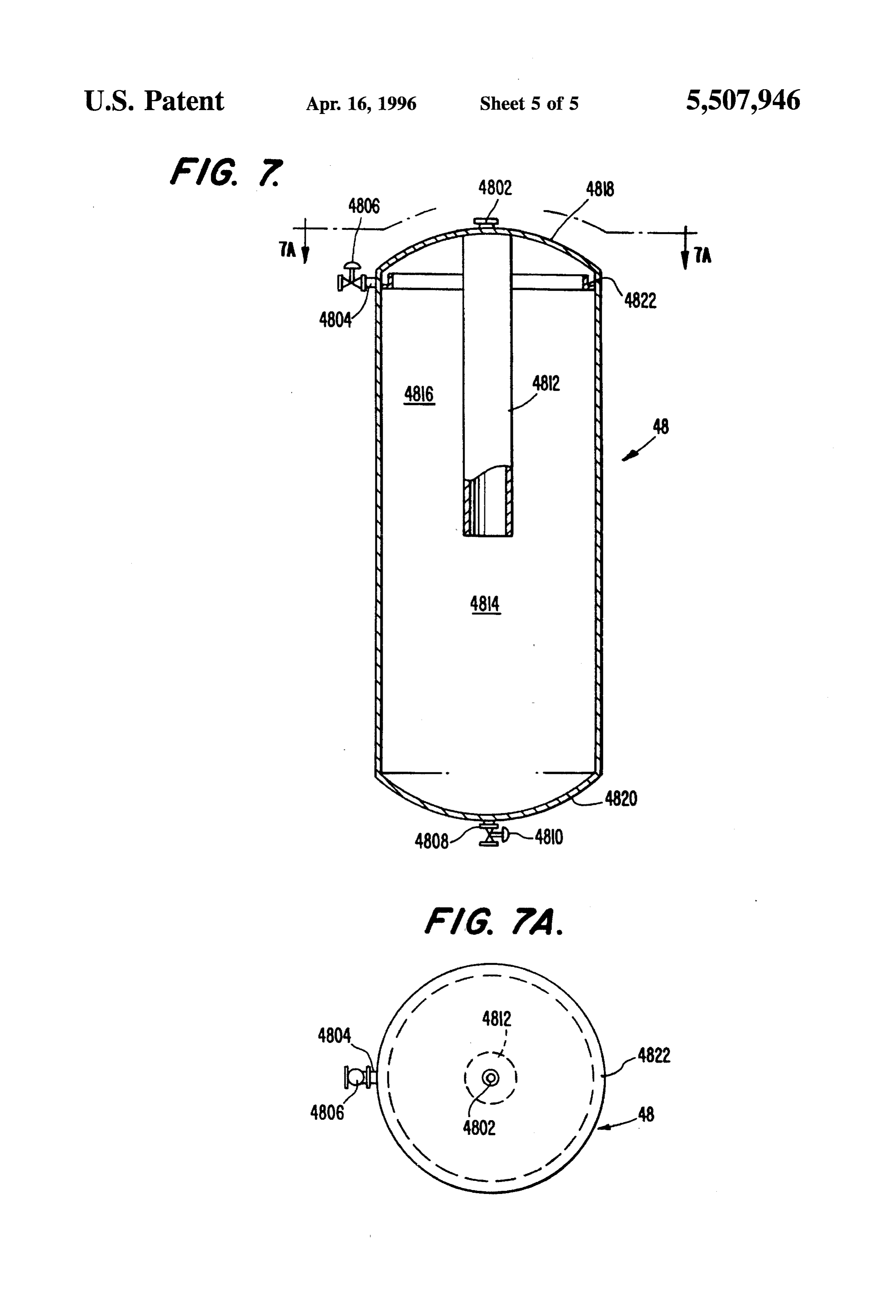
FIG. 6 is a side cross-sectional view of a chlorine contact morning periods. With the development of the centrifugal and reuse storage tank which may be used in the present 50 oxygenator which can efficiently operate at liquid levels of invention. from two feet to 100 feet, it is possible to provide storage of FIG. 6A is a plan view of the chlorinc contact and reuse wastewater in excess of the average daily flow at the storage tank of FIG. 6 along line 6A-6A. treatment plant. To improve the efficiency of the present FIG. 7 is a side cross-sectional view of a concentration invention, a certain amount of wastewater storage at the column which may be used in the present invention. 55 treatment plant can be provided for dissolved oxygen con FIG. 7A is a plan view of the concentration column of trol. Further, modification of the current design standards for FIG. 7 along line 7A-7A. collection and transmission systems can obtain the best cost efficiency as compared with treatment plant storage.
DETAILED DESCRIPTION OF THE The current design practice for pump station wetwells in PREFERRED EMBODIMENTS 60 wastewater collection and transmission systems of necessity have to be confined to the smallest possible retention volume
The treatment of wastewater does not begin at the treat of the wastewater for the flow conditions. This restriction is ment plant. According to the present invention, the waste imposed by the settling of solids in the wetwell and the water, specifically the bacteria therein, is controlled in the inability to control dissolved oxygen levels in the wetwell. collection and transmission system. The oxygen content is 65 With the availability of the centrifugal oxygenator, it is controlled to a level such that the growth of anaerobic possible to totally remove this design restriction. Wetwells bacteria is substantially eliminated and the growth of aerobic can now become a storage facility for wastewater flow in
Page 10
excess of the average daily flow. In order to control the operated without control of bacteria growth and at variable dissolved oxygen levels in the collection and transmission flow rates that can have as much as a 25 time variation in the systems, retention times in pump station wetWells are the input flow from the collection and transmission systems. least costly method of providing the time required for the The only means of non-destructive control of bacteria controlled transfer of dissolved oxygen into the wastewater. growth is the use of the control of dissolved oxygen in the As the centrifugal oxygenator provides both efficient trans collection and transmission systems. This control of dis fer of oxygen as well as hydraulic flow velocity at its solved oxygen eliminates the growth of anaerobic bacteria directionalized discharge, settling of wastewater solids in and minimizes the growth of aerobic bacteria by limiting the the wetwells is no longer a consideration in the design of amount of dissolved oxygen available for growth. wetwells of pumping stations. Wastewater collection and 10 In order to control dissolved oxygen in the collection and transmission systems pump station wetwells when equipped the transmission systems, retention time for the transfer of with centrifugal oxygenators, which do not affect the opera tion of centrifugal pumping equipment, can now be designed. oxygen into the wastewater must be provided within these systems by the use of oversize wetwells for pump stations to provide any retention time for the wastewater that is the and the injection of oxygen in long retention pipeline most efficient for system flow requirements that vary from 15 systems.
system to system. As long as the retention time needed for This requirement is compatible with the requirement for flow control exceeds the retention time needed for dissolved the constant flow rate needed for efficient operation of the oxygen control, sizing of the storage wetwell would be separation stages of the energy recovery sludge free treat determined by the systems' flow requirements. This method ment process. Using centrifugal oxygenators in pump station of meeting the constant flow requirement of the energy 20 wetwells for dissolved oxygen control also allows the size of recovery sludge free wastewater treatment process of the present invention provides a second major benefit by the peak wetwells of pump stations to be increased for storage of flow that always occurs in collection systems.
increasing the capacity of existing transmission pipelines and reducing the size requirement and cost of future pipeline is possiblethetostorage
Using of peak flows in collection systems, it systems. In addition, the energy recovery sludge free waste 25 at the treatment plantdecrease greatly for the amount of storage needed efficient operation. At the same water treatment process disclosed herein eliminates the time, the use of storage wetwells provides a great amount of requirement for variable speed pump drives and reduces the cost savings and a reduction in operating problems when electrical power consumption of any wastewater system. compared to the currently used inflow demand systems. As all wastewater transmission pipeline systems are cur rently designed for handling the peak flow requirement of 30 The constant rate transmission system eliminates the over 200% of average daily flow, retention time in the design constraints of the inflow demand system which pipeline can result in the development of dangerous prob requires the output of the pump station to generally match lems in the pipeline system. During peak flow periods, most the variable inflow of the pump station. With use of constant speed pumps operating on a selectable time basis with the pipeline systems are designed so that the retention time is inadequate to allow the depletion of the dissolved oxygen 35 excess incoming flow stored in the wetwell, control of dissolved oxygen and a nearly constant rate of flow can be levels in the wastewater by bacterial action. During the delivered to the treatment plant. period of average daily flow, the retention time is at least doubled and during night time or early morning periods, the The constant pressure transmission system is similar to retention time in pipeline systems can be increased by a the constant rate transmission system in that it also uses factor of 10 to 20 times which, in some cases, results in 40 storage type pump station wetwells for dissolved oxygen extensive problems of explosion hazard, corrosion of con control and storage of excess incoming flows. This system crete and metal components, foul odor, toxic health hazards would be used in some cases where it is not possible to and treatment plant operational problems. provide a large enough wetwell for the incoming flow With a method for the control of bacterial growth in storage. The transmission system that would require the wastewater collection and transmission systems and the 45 constant pressure transmission design would have a mixture of constant speed pumps and variable speed pumps. The ability to operate the treatment process at a constant flow constant speed pump stations would be operated in the same rate, the efficiency of the physical separation of the solids from the water carrier and the preservation of the combus manner as in the constant rate system and the variable speed tion valve of the solids, coupled with the treatment of the pumping station would have its pump speed, and therefor its soluble organic matter, makes the energy recovery sludge 50 output, controlled by the placement of the normally used transducer speed control sensor operated based on the pres free process described herein possible. This process com sure in the force main in place of the liquid level in the bines the separation of solids by both fiber assisted pressur wetwell. This constant pressure system provides the same ized air flotation; settling using a high liquid level depth which is normally double those used in all current processes; constant flow rate to the treatment plant with the same and a solids collection and removal system that uses a 55 operating cost savings as the constant rate system. concentric circular flow pattern in place of a pusher-type FIG. 1 shows a preferred treatment flow diagram for rake system for moving the settled solids to a central point wastewater which has been controlled in the transmission of discharge. The multiple process reguirement is needed and collection system as previously described. due to the variation in wastewater from system to system and As shown in FIG. 1, an in-line grinder/comminutor 1 is efficient operation of the overall treatment process. 60 provided for the reduction of large size solids in the waste For the efficient separation of the solids from the liquid water to a more suitable size for the physical separation phase of wastewater by the energy recovery sludge free process. The wastewater then flows to constant rate feed and process, the growth of both aerobic and anaerobic bacteria dissolved oxygen control tanks 2. must be controlled in the wastewater collection and trans Constant rate feed and dissolved oxygen control tanks 2 mission systems. Also, for efficient separation of the solids 65 have a dual function of storing excess flow into the waste from the liquid phase, it is necessary to operate the treatment water treatment plant and stabilizing the dissolved oxygen plant at a uniform flow rate. Current treatment processes are concentration at an appropriate level as explained above
Page 11
such that the growth of anaerobic bacteria is substantially 508 of the column 5 has near its bottom the air distributor eliminated and the growth of aerobic bacteria is minimized. plate 502 which directs the flow of air into the center of the In an average case, the level of dissolved oxygen may be column 5 in order to allow complete contact with the first between 0.5 and 1.0 parts per million (ppm). For most stage air disperser impeller 614. Both the first dispersion efficient operation, the treatment process is operated at a 5 stage 508 and the second dispersion stage 516 contain constant flow rate and the sizing of the tank capacities are vertical baffles 510 to improve the dispersion of the air into based on the design of the collection and transmission the wastewater. The second dispersion stage 516 has a systems and the ability to provide constant flow rates to the horizontal baffle 504 to improve the flow pattern and effi treatment plant. The use of a constant pressure or a constant rate design system in the transmission section supplying the 10 second stage second ciency of the air stage air dispersion impeller 606. The dispersion column 8 can be of similar wastewater treatment plant as previously described will construction to the first stage air dispersion column 5 and, if minimize the size of the constant rate feed and dissolved oxygen control tanks 2. required, additional stages could be used in the design of Centrifugal oxygenators 3 are installed in the constant rate either air dispersion column 5 or 8 to obtain suitable air feed and dissolved oxygen control tanks 2 for the dual 15 drives shaftin603 dispersion the wastewater. The air disperser drive 602 and impellets 606 and 614, and would be purpose of suspending solids by hydraulic flow and control similar for both the first stage air dispersion column 5 and ling the dissolved oxygen levels. Based on the ability of the the second stage air dispersion column S. The air pressure centrifugal oxygenator 3 to provide high efficiency oxygen within the dispersion column 5 is controlled by the use of a transfer at any liquid level above the two foot minimum pressure relief valve 518 placed in the top head of the level, the constant rate feed and dissolved oxygen control 20 column 5. The wastewater air dispersion is discharged from tanks 2 can be operated at any variable liquid level in excess the column 5 near the top head 520 of the column 5, i.e., just of two feet to as much as fifty feet. The centrifugal oxygen below horizontal baffle 504 through outlet 521. The top head ator 3 is able to operate at any gas flow rate from zero to the 520 of the column 5 would have a flange-type mounting for maximum for the size unit used without any type of plug the first stage air disperser unit. ging. The centrifugal oxygenator 3 also provides for start/ 25 stop gas flow for control of the dissolved oxygen level in the The first stage air disperser 6 is an electric drive high constant rate feed and dissolved oxygen control tanks 2 shear multi-stage rotating impeller unit with the impellers without affecting the hydraulic suspension of the wastewater 606 and 614 designed for dispersion of the air into the solids. wastewater flow. The impellers are selected from the maxi A solids handling type of centrifugal pump 4 is used to mum required air flow rate which, in turn, must be deter 30 mined by (1) the concentration of the solids in the waste transfer the wastewater from the constant rate feed and dissolved oxygen control tanks 2 to the first stage air water, (2) the amount of fiber slurry added to the wastewater, dispersion column 5. Due to the variable height of the (3) the vertical liquid flow velocity in the column, (4) the wastewater in the constant rate feed and dissolved oxygen level of back pressure required for control of the air bubble rise rate, and (5) the volume of air required for efficient control tank 2 and a constant injection pressure required by 35 flotation separation of the wastewater solids. the first stage air dispersion column 5, the centrifugal pump Referring back to FIG. 1, the second stage pressurized air 4 must utilize either a flow control valve system or a variable dispersion column 8 would be the same design as the first speed drive system. Downstream of the centrifugal pump stage pressurized air dispersion column 5, but in the average control valve, a pipeline inject point is located prior to the case, somewhat smaller in diameter and designed for lower first stage air dispersion column 5 entry point. Fiber slurry 40 air flow rates.
produced by the paper to fiber with high shear mixer 45 is injected into the pipeline by the fiber slurry transfer pump 67 The second stage air disperser 9 would also be similar to for contact with the wastewater solids. The fiber particles, the first stage air disperser 6, but in the average case, a due to their surface nature, attach themselves to the waste smaller electric motor drive could be used. water solid particles and thereby increase the separation 45 The pressurized airflotation utilizes a two-stage system of efficiency of the pressurized air separation columns 7 and vertical columns 7 and 10 with compressed air dispersed in 10. To accomplish this, air is dispersed in the wastewater in units 5 and 8 as described prior to the introduction of the first and second stage air dispersion columns 5 and 8, wastewater and the air dispersion near the bottom of the equipped with air dispersers 6 and 9, respectively. columns. The vertical height and the internal flow patterns In particular, as shown in FIGS. 2, 2A, 2B and 2C, the first 50 within the columns 7 and 10 must be determined by the stage air dispersion column 5 is a vertical pressurized unit composition of the wastewater solids. In general, the pres with the interior of the column 5 divided into a minimum of surization of the first stage column 7 will be higher than the two sections 508 and 516. The flow from the centrifugal second stage column 10 because the vertical rise rate of the pump 4 is introduced into the lowest section of the column air bubble is a function of the amount of pressure above that 5 near the bottom of the section, but above the air distributor 55 of the normal atmosphere pressure at the location of the plate 502 through inlet 506. The bottom column head 522 treatment plant.
contains the air supply inlet flange 524 which provides the The ability of separation of low solids concentrations in a air supply below the air distributor plate 502. The air water phase by the air flotation process requires the attach distributor plate 502 provides for the introduction of the ment of the rising air bubble to a solid particle with control compressed air in a uniform manner through holes 503 to the 60 of the rise rate to a low enough level to maintain contact with incoming wastewater. The lowest section 508 of the column the solid particle. Since the liquid level in the column can 5 is separated from the second stage 516 and any additional vary based on the composition of the solids in the waste stages by a horizontal baffle 512 which provides the dual water, the control of the air pressure above atmospheric function of flow pattern control for efficient gas dispersion pressure above the top of the liquid level in the column can and directing the flow of the first stage 508 into the center 65 be adjusted for maximum solid separation efficiency. The of the column 5 to allow complete contact with the second second stage pressurized air separation column 10 would stage air dispersion impeller 606. The first dispersion stage utilize a smaller diameter for almost the same liquid flow
Page 12
that would result in a greater vertical rise velocity of the 702 by the separated water discharge outlet 710. The fixed liquid and solid phase and a lower pressurization that would vertical flight light density solids conveyor 716 allows the increase the rise rate of the air that was introduced by a light density solids to collect under the top head 702 between second stage air dispersion unit 8, 9 that would receive the the outer wall of the column and the separated water flow from the first stage separation column 7. The first stage discharge pipe 712 where they are discharged under the pressurized air separation column 7 would be selected and column operating pressure through the light density solids designed for smaller size particles using higher rates of discharge outlet 708 using an exterior control valve. liquid and air bubble rise rates. The solids separated at the Referring back to FIG. 1, the second stage pressurized air upper level of both the first and second stage columns 7 and separation column 10 would be similar in design to the first 10 would be withdrawn by use of a control valve and 10 stage pressurized air separation column 7, but in the average discharged from the columns using the internal pressure of case, somewhat smaller in diameter and with the internal the column. Any solid material with a high settling rate pressure controlled at a lower level than the first stage would be collected in the bottom of both the first and second pressurized air separation column 7 for control of both the stage columns 7 and 10 and discharged by a control valve air bubble rise rate and the vertical liquid velocity. utilizing the pressurization of the columns to a secondary 15 The floatable solids from the top stage of both the first and concentration column 48. second stage separation columns 7 and 10 would be dis The internal flow pattern of both the first and second stage charged under pressure by a control valve and transferred to separation columns 7 and 10 utilizes a circulating horizontal the slurry mixing tank 42 for mixing with other flow streams directionalized flow of the wastewater and air dispersion. prior to dewatering.
The bottom stage of both columns allows the flow to either 20 The high density solids collected in the bottom stage of travel downwardly into the high density solids removal stage both the first and second stage pressurized air separation or upwardly into the first flotation stage of the columns. columns 7 and 10 would be discharged under pressure by Additional flotation stages are stacked above the first flota control valves to a secondary concentration column 48. tion stage, but these stages have a flow pattern somewhat The concentration column 48 would also be a pressurized different from the first stage. The vertical travel flow path 25 stage with the underflow discharged into the same slurry would be the same as the first stage, but a second flow tank 42 as the solids from the top flotation stage of the first pattern would be used for the separated liquid phase. The and second stage separation columns 7 and 10. The overflow liquid flow would utilize a horizontal slotted opening located of the concentration column 48 would be discharged into the directly above the horizontal stage separation baffle that constant rate feed and dissolved oxygen control tank 2. would discharge into a vertical closed pipe or formed section 30 of the column to remove the separated liquid phase, as After the separation of both the floatable solids and the described hereinafter, high density settleable solids from the two-stage pressurized The first stage pressurized air separation column 7 (shown air separation columns 7 and 10, the wastewater would be in more detail in FIGS. 3, 3A and 3B) has a vertical two discharged under pressure to a series of batch/continuous section design with the inflow of the wastewater and air 35 aeration tanks 11 with operating liquid levels of a minimum of twenty feet or up to fifty feet depending on the liquid level dispersion introduced into the column settling section 730 of the pressurized air separation columns 7 and 10 and their by way of the circular ring inlet manifold 724 and the operating pressure. As one of the aeration tanks 11 is being opposed liquid velocity inlet nozzles 726. By utilizing an filled opposed liquid velocity inlet design of the nozzles 726, the other tanks 11flow by the from the separation columns 7 and 10, are used for bacterial oxidation of the soluble velocity head of the liquid is dissipated and a low velocity 40 circular flow pattern is created in the center of the column 7. organic material or for providing the constant rate feed to the In the low velocity circular flow pattern of the center of the settling tanks 17 of the invention. column 7, high density solids (grit and other inorganic By eliminating variations in flow rates and the inaccuracy solids) settle to the bottom of the column bottom head 704 of a continuous flow-through system, accurate control of the and are discharged under column pressure through the high 45 bacteria action by control of dissolved oxygen and the density solids discharge 706 by use of an exterior control concentration of bacteria are possible, which results in a valve. The light density solids and waster phase rise verti massive reduction in the requirement for return of highly cally in the low velocity circular flow pattern of the column active sludge to provide the needed concentrations of bac settling section 730 and are discharged into the column teria for rapid growth. The retention time required in the flotation section 728 which is divided from the column 50 batch/continuous aeration tanks 11 needs only to be suffi settling section 730 by the column divider plate 718. The cient for the oxidation of the soluble matter in the waste light density solids and the water phase are introduced into water. In the average case, this can be done in one to three the column flotation section 728 using the low density solids hours, with proper control of the amount of activated sludge and water directionalized inlet distribution 720 and the baffle addition and the control of the dissolved oxygen level. for directionalized flow 722. The low density solids and 55 The aeration tanks 11 receive their input flow from the water phase travel in a circular vertical rise pattern over the second stage separation column 10 under pressure and the fixed vertical flight light density solids conveyor 716. The maximum height of the aeration tanks 11 is determined by center of the fixed vertical flight light density solids con the liquid level and operating pressure of the second stage veyor 716 is a circular enclosed pipe section which forms the pressurized air separation column 10. The tanks 11 are separated water discharge pipe 712. Water is separated from 60 operated in a batch/continuous method with the constant rate the light density solids using inlet openings 714 located in flow from the second stage separation column 10 directed to the separated water discharge pipe 712 at a position just one of the aeration tanks 11 by control valves. The aeration above the points of flight where the light density solids tanks 11 are designed for a retention time of one to three conveyor 716 comes in contact with the separated water hours depending on the amount of soluble material in the discharge pipe. The collector discharge water flow inlet 65 wastewater received from the second stage pressurized air openings 14 of the separated water discharge pipe 712 allow separation column 10. The aeration tanks 11 are equipped the discharge of the separated water through the top head with a centrifugal oxygenator 3 for solid suspension and
Page 13
oxygen transfer at variable liquid levels. Unlike aeration plant. The variation in wastewater composition from system tanks currently in use, the batch process eliminates the to system requires individual selection of the coagulant aid variables of a flow-through system and allows for control of that will be the most effective in assisting the settling of the both the bacteria concentrations and the level of dissolved solids in the clarifier tanks 17. oxygen in the aeration tanks 11. The control of the bacteria The coagulant feed pump 14 obtains its supply of coagul concentration would be by the addition of a defined amount lant solution from the coagulant feed tanks 13 and injects the of return activated sludge with known bacteria concentra solution into the pressurized pipeline transferring the waste tions from the sludge storage and activation tank 20. The water from the aeration tanks 11 to the clarifier tanks 17 dissolved oxygen level in the aeration tanks 11 is controlled provided with coil track conveyor 16. at a lower level as compared to current process designs for 10 The coagulant mixers 15 are standard solution mechanical aeration tanks, the purpose of which is to oxidize wastewater drive electric motor-driven units of suitable size to provide solids as well as soluble material. In the average case, this solution of solid materials in the internal reuse effluent used dissolved oxygen level would be in the range of 2 to 4 ppm. in the coagulant feed tanks 13.
The use of the centrifugal oxygenator 3 provides the ability to maintain this dissolved oxygen level during the filling and 15 in The liquid level in the clarifier, or settling tank 17, would almost all cases be at least double that of currently used discharge cycle of the aeration tanks 11. The discharge from systems. With the use of a constant flow rate input to the each of the aeration tanks 11 would be to the clarifier tanks 17 using an aeration-tank-to-clarifier-transfer-pump 12 with clarifier tank 17 coupled with the removal of most of the a valved flow rate control system that would provide a wastewater solids in the pressurized air separation columns constant rate of feed to the clarifier tanks 17. 7 and 10 and the control of dissolved oxygen at all times 20 from the feed transferred from the aeration tanks 11, bacte
Due to the small amount of solids, the low concentration rial growth in the clarifier tanks 17 can be controlled. The of active bacteria and the controlled level of dissolved retention time in the clarifier tanks 17 would be based on oxygen, it is possible to use a high efficiency deep liquid optimum settling time requirements without consideration level settling system. Also, the use of a constant flow rate of anaerobic bacterial growth.
through the deep liquid level settling system greatly 25 The sludge from the settling tanks 17 is transferred by increases the separation efficiency as compared to currently gravity into a small storage tank 18 which, in turn, is then used low liquid level variable flow clarifiers. The deep liquid transferred as needed by a centrifugal pump 19 to the slurry level settling system with coil track solids conveyor is tank 42 feeding the dewatering system. Sludge from the shown in more detail in FIGS. 4, 4A and 4B. The feed to the settling system (clarifier tanks) 17 is provided from the 30 settling tanks 17 needed to meet the requirements for activated-sludge in the aeration tanks 11 is stored in the batch/continuous aeration tanks 11 by the aeration tanks to sludge storage and activation tank 20. clarifier transfer pump 12 using a control valve to provide a constant flow rate. Coagulant chemicals are added from the As the sludge underflow from the settling tank 17 has a coagulant tanks 13 with mixer 15 by the coagulant pump 14. low concentration of both dissolved oxygen and aerobic This flow is made to the settling system (clarifier tanks) 17 35 bacteria, it is necessary to store the sludge in a controlled aeration tank 20 in order to increase these concentrations to through the inlet flow directional circular containment baffle needed levels. The sludge storage and activation tank 20 is 1706 which provides the coagulant contact zone 1710. From of suitable size to provide retention time to meet the required the coagulant contact zone, the downward flow passes into the settling zone 1712 of the clarifier tank 17. The water concentration of bacteria for return to the aeration tank phase then passes through the clarified water phase rise zone 40 system. By using the centrifugal oxygenator 3 as a means of 1708 into the overflow weir 1704 and through the clarified control of the dissolved oxygen at variable liquid levels, the water phase discharge 1714. The solids deposited into the concentration of the aerobic bacteria can be maintained in bottom of the settling zone 1712 are moved to the settled the storage and activation tank 20 so that a known amount solids discharge 1716 by the coil track conveyor 16. The coil of activated sludge can be transferred to the aeration tanks 11 to meet the requirement of the bacterial oxidation of the track conveyor 16 consists of an electric motor drive coil 45 soluble matter in the wastewater. The return of the activated track conveyor gear reduction drive 1602, the coil track sludge from the storage and activation tank 20 is by the use drive shaft 1604, the coil track conveyor drive shaft bearing of a centrifugal pump 21 with either flow measuring equip 1606, the coil track conveyor support member 1608 and the ment or a timed pumping cycle control. coil track 1610. The coil track conveyor action for the movement of solids is completely different from the solids 50 The sludge transfer supply tank 18 is a vertical open top moving equipment currently in use in wastewater treatment tank and would receive the excess sludge flow from the plants that utilize a racking or pushing action to move the bottom of the clarifier tank 17 by gravity. The control of the solids to a discharge point. The coil track conveyor 16 feed of excess sludge would be based on the requirement of applies a rotary centrifugal squeeze principle to transport the the level in the sludge storage and activation tank 20. The solids across the bottom of the settling tank to a point of 55 sludge transfer supply tank 18 would serve as a wetwell for discharge. The rotary centrifugal squeeze movement of the sludge transfer pump 19 and would contain a small solids slurry reduces the amount of solids re-suspended as amount of storage capacity that would allow selection of the compared to the raking or pushing action of currently time cycle for transfer of the excess sludge to the dewatering applied solids movement systems used in wastewater treat feed slurry tank 42.
ment clarifiers. 60 The sludge transfer pump 19 takes its suction from the Referring back to FIG. 1, the coagulant feed tanks 13 are sludge transfer supply tank 18 and transfers the sludge vertical open top preparation and storage tanks suitable for through a pipeline system to the dewatering feed slurry tank preparation and storage of several types of solutions of 42, as required.
chemicals which could be used in assisting the settling of The sludge storage and activation tank 20 is supplied by solids that were not removed in the pressurized air separa 65 gravity flow from the bottom of the clarifier tanks 17. A tion columns 7 and 10. The selection and concentrations of liquid level control in the sludge storage and activation tank the coagulant aids would be based on settling tests in each 20 would be used for control of the sludge flow from the
Page 14
clarifier tank 17 into the sludge storage and activation tank much more efficient than in the sand or sand-and-coal media 20 with all excess sludge being sent by control valves to the systems that contain only hard particle surfaces. Removal sludge transfer supply tank 18. The sludge storage and and replacement of the media in the contact columns does activation tank 20 uses centrifugal oxygenators 3 for control not require labor input and can be done on a fully automated of the dissolved oxygen level in the sludge storage and basis without affecting the through-put flow of the waste activation tank 20. As a high concentration of bacteria is water system. Loading of media into each individual contact needed in the activated sludge returned to the aeration tanks column 22 is done by transfer of the coal and paper slurry 11, the dissolved oxygen level would be controlled in a from the storage preparation area by a centrifugal slurry normal range of 5 ppm. With a known bacterial requirement pump 47 and pipeline system with automatic valve control. in the batch/continuous aeration tanks 11 and a known 10 The reused effluent used to prepare the media slurry is concentration of bacteria in the sludge storage and activation discharged into the inlet of the contact column system and, tank 20, an accurate and defined return of the activated in turn, returned to the chlorine contact and reuse storage sludge solids can be made. Only the minimum amount of tank 25. The spent media slurry is transferred to the slurry activated return sludge would be used for the necessary tank 42 feeding the dewatering system and only the excess bacterial oxidation of the soluble matter in the wastewater. 15 water from the dewatering system is returned to the constant The return activated sludge transfer pump 21 could be rate feed an dissolved oxygen control tank 2 which, in turn, either a centrifugal type with flow control or flow measuring is reintroduced into the wastewater flow through the plant. equipment or a positive displacement pump with a timed In particular, the effluent contact columns 22 are vertical operating cycle. The pump would take suction from the open top columns with (as shown in FIG. 5) a support sludge storage and activation tank 20 and transfer the sludge 20 system near the bottom of the column normally consisting of through a pipeline and directional valve system to any one a perforated support plate 2202 and a woven metal, cloth or of the aeration tanks 11 as selected. plastic media support member 2204. Located directly below The contact columns 22 are preferred filtering media and the support system is a compressed air inlet pipe system receive their input flow by gravity from the overflow of the 25 2206 for use in connection with the removal of the spent contact media. The flow throughout the contact columns 22 settling tanks 17. Due to the high liquid level of the settling is by gravity based on the level of the discharge from the tanks 17, the contact columns 22 operate on a gravity flow overflow of the clarifier tanks 17. Any wastewater solids not basis. The contact columns 22 consist of a flow-through removed in the clarifier tanks 17 flow downwardly through support system of either perforated metal plate material a coal and paper fiber media 2208 of the contact columns 22 covered with wire support screen or any other type of 30 in which the solids are trapped on or in the particles of the flow-through support system that will contain the contact coal or deposited on the paper fiber. The level 2210 of the media and allow the liquid phase to flow through the contact area of the deep bed media and allow the backflow of mixed media 2208 and also the percentage of coal to paper fiber in the media would be determined on each installation compressed air for the discharge of the spent media. in order to provide the most efficient operation of the The contact media is a mixture of pulverized coal and 35 effluent contact columns 22. The diameter of the effluent shredded waste paper fibers or similar waste material. The contact columns 22 would also be established by the number slurry is prepared in a mixing tank 46 located in the fuel of columns to be installed and the capacity of the wastewater preparation area and transferred to each individual contact treatment plant. The loading of the media 2208 into the column by a centrifugal pump 47 and pipeline system with columns would be an individual operation for each column control valves. The spent contact media is removed as 40 using a batch process with the mixed media prepared in the required from each of the contact columns 22 through a coal and paper fiber slurry tank with mixer 46 and the control valve piping system located just above the media centrifugal slurry pump 47 for transfer of the coal/paper support using the gravity flow from the settling tanks 17 and slurry. The mixed media containing the correct ratio of coal the introduction of compressed air through a distributor pipe located directly below the media support system. The spent 45 slurrypaper and tank fiber would be prepared in the coal and paper fiber with mixer 46 by using the feed from the paper media slurry is discharged into a storage tank 27 equipped to fiber tank with high shear mixer 45 and coal directly from with a mixer 28 and, in turn, is transferred, as needed, to the the pulverized coal storage tank 38. Additions of internal slurry tank 42 feeding the dewatering system by a centrifu reuse effluent would be used to provide proper dilution of the gal slurry pump 29 and pipeline system. slurry to a suitable level for pipeline transfer to an effluent Unlike the currently used shallow bed sand or sand-and 50 contact column 22 by way of the media inlet control valve coal filter systems, the contact columns 22 would not use a 2226 and the media inlet 2228. Additional internal reuse water backwash system that in almost all cases requires a effluent would be used to flush the pipeline after transfer to large amount of water for cleaning of the solids trapped in prevent solids settling and plugging of the pipeline system. the media. The return of this backwash water to the treat The excess flow of the internal reuse effluent could also be ment system can cause a large increase in the flow-though 55 used to compact the mixed media 2208 in the effluent demands of the treatment plant. Also, the replacement of the contact columns 22, if needed. After flowing through the media, when required, can present major costs in both labor media bed, the water phase would be returned to chlorine and out-of-service time. contact and reuse storage tank 25 by gravity flow through a The contact columns 22, due to the highliquid level in the discharge pipeline 2212 connecting the effluent contact clarifier tank 17, can use a media depth of from four feet to 60 columns 22 to the chlorine contact and reuse storage tank 25. as much as fifteen feet to meet the effluent disposal require The operation of the effluent contact columns 22 would be ments of each wastewater treatment system for the removal on the basis of the differential pressure over the height of the of solids and bacteria by attachment of the solid particles and media bed. High differential pressure would indicate the bacteria to the surface of the coal and shredded paper fiber mixed media bed was loaded with wastewater solids mixed media. As the media contains both hard particles and 65 removed from the overflow of the clarifier tanks 17. When fiber surfaces, attachment of the small size solids that have this occurs, a control valve 2214 on the column discharge not been separated in either the flotation or settling stages is pipe 2212 is closed and a media discharge control valve
Page 15
2218, in a location directly above the support system for the on plant capacity and a minimum retention time of one hour. media, would open. Compressed air would be introduced Underflow baffles would be used to allow the tank 25 to through the air inlet 2206 by the air inlet control valve 2224 operate at variable liquid levels. The chlorine contact and directly below the support system for the media which, in reuse storage tank 25 would also act as a wetwell for the turn, would flow upwardly at a high velocity to break up the water reuse centrifugal pump system 26 which would take compacted media bed 2208 and allow its removal by gravity its supply of water from the chlorine contact and reuse flow by the effluent received from the overflow of the storage tank 25 as shown in FIG. 1. As the flow of the clarifier tanks 17. The spent mixed media 2208 would flow wastewater treatment plant is a constant rate, storage is by gravity through the media discharge 2216 and media provided for the internal effluent reuse flow to the condenser 32. Almost all of the internal reuse flow would be directed discharge control valve 2218 to the spent coal/paper re 10 to the condenser 32 of the electric power generation section slurry tank 27. After removal of the spent media 2208, the of the plant. Other internal uses of the effluent reuse water operational cycle would be repeated starting with the media 2208 loading procedure outlined above. During the period of system would be (1) water supply to the coagulant aid system 13, 15, (2) gas chlorinator system 23, (3) spent media media 2208 loading, the inlet control valve 2222 located on coal/paper re-slurry tank 27, (4) coal and paper fiber slurry the column inlet 2220 would be closed to prevent the 15 tank 46, (5) paper to fiber tank with high shear mixer 45, (6) introduction of untreated flow out of the contact column 22. ash slurry tank 5.5, and (7) wet scrubber system 63. The number and size of the columns would be based on plant After use as cooling water in the condenser 32 of the rating with a minimum of one column out of service for power plant section of the treatment plant, the internal reuse media replacement. effluent is returned for final treatment in the effluent storage The gravity overflow from the clarifier tanks 17 is treated 20 and dissolved oxygen control tank 35. Due to the possible by the addition of chlorine, or other similar chemicals, prior temperature rise caused by the heat transfer of the condenser to its introduction into the contact columns 22 in order to 32, adjustment of the dissolved oxygen levels of the effluent maintain a high level of chlorine concentration in the contact may be required. In most cases, the use of air to reach column. The addition of chlorine at this point terminates the 25 saturation levels of dissolved oxygen, which is sometimes growth and destroys activity of the aerobic bacteria which, required for effluent reuse, will require many hours of in turn, assists in the bacterial reduction of the wastewater retention with standard aeration devices and will not allow effluent that occurs in the coal and fiber media bed 2208 of operation of the storage tanks at variable liquid levels. The the contact columns 22. present invention again utilizes the ability of the centrifugal oxygenator 3 to operate with a pure oxygen feed directly
For normal installation, a gas chlorinator 23 shown in from storage cylinders 37 to rapidly and efficiently reach a FIG. 1 may be provided, although other chemicals such as 30 saturation level of dissolved oxygen even under variable ozone could be used in place of the gas chlorinator 23. The levels of storage tank operation. gas chlorinator 23 would be supplied with internal reuse Effluent storage and dissolved oxygen control tanks 35 effluent under necessary pressure to provide solution of the would be of similar design to the chlorine contact and reuse chlorine gas into the water. The resulting solution would be storage tank 25 with internal flow directional baffles to injected into the discharge pipeline of the clarifier tank 17 35 provide maximum retention time without short-circuiting prior to its entrance to the effluent contact columns 22. The and would also utilize underflow internal baffles to allow for introduction of chlorine at this point is for the purpose of variable level operation of the storage tank 35. The number providing assistance in the reduction of bacteria provided by and size of the effluent storage and dissolved oxygen control the media 2208 of the effluent contact columns 22.
40 tanks 35 would be dependent on the exterior disposal
The chlorine gas supplied to the gas chlorinator 23 may be requirement of the system. If conditions allowed the con provided by, e.g., one ton or smaller pressurized storage stant rate use of the effluent, only a small amount of total cylinders 24. retention time would be required for the control of the After discharge from the contact columns 22, the effluent dissolved oxygen levels which would, in the average case, flows by gravity into the chlorine contact and reuse storage 45 be less than one hour of plant through-put. Except in the case tank 25 (shown in more detail in FIGS. 6 and 6A) through of tropical locations, the use of the exterior disposal dis inlet 2510. As with the entire energy recovery sludge free solved oxygen control systems would only be required treatment process of the present invention, the height of the during summer months or periods of high water tempera chlorine contact and reuse storage tank 25 would preferably tre.
be more than double that currently used. The interior of the 50 The effluent internal reuse supply centrifugal pump sys tank 25 would be equipped with flow directional baffles tem 26 would take suction from the chlorine contact and 2502-2508, top baffle support plate 2514 and bottom baffle reuse storage tank 25 and would be sized to accept the support plate 2516 that would prevent any short-circuiting of complete plant flow. The system could, in some cases, be a the flow and ensure adequate retention time for removal of single unit; in the average case, due to the different flow and excess chlorine by air stripping using a centrifugal oxygen 55 pressure requirements, multiple units would be needed. The ator 3. The chlorine contact and reuse storage tank 25 would balance of the flow of the effluent internal reuse supply be sized on the variable effluent reuse factor which would centrifugal pump system 26, after meeting the needs of (1) always be in excess of the time required for removal of the the coagulant feed tanks 13, (2) gas chlorinator 23, (3) spent excess chlorine from the wastewater prior to its reuse in the coal/paper re-slurry tank 27, (4) paper to fiber tank with high condenser 32 and other needs within the treatment process 60 shear mixer 45, (5) coal and paper fiber slurry tank with system. mixer 46, (6) ash slurry tank S5, and (7) the wet scrubber The internal directionalized flow baffles 2502-2508 of the system 63, would be sent to condenser 32 and, in turn, chlorine contact and reuse storage tank 25 would prevent the returned under pressure of the water reuse supply pump inlet flow from reaching the outlet of the tank 25 without system 26 to the effluent storage and dissolved oxygen being subject to the minimum retention time required for the 65 control tank 35.
reduction of excess chlorine by air stripping using a cen The spent coal/paper re-slurry tank 27 can be a vertical trifugal oxygenator 3. The size of the tank 25 would be based open top tank sized to retain the output of solids and liquids
Page 16
produced by the removal of the spent media of the effluent through volume and the short retention time in the collector contact columns 22. The spent coal/paper re-slurry tank 27 of the centrifugal oxygenator 3 coupled with the high shear would also receive additional reuse water as required for agitation, freezing or dispersion problems would not be pipeline flushing from the internal effluent reuse supply encountered with a low temperature oxygen feed. centrifugal pump system 26. The effluent disposal centrifugal pump system 36 would The spent coal/paper re-slurry tank 27 could be equipped be suitable for the individual plant effluent disposal needs. with, e.g., an electric driven mechanical mixer 28 of suffi As the effluent quality would be suitable for any type of cient horsepower to provide complete suspension of solids non-potable water usage such as lawn watering, irrigation, in the liquid carrier. commercial applications or environmental reuse, the pres The spent coal/paper transfer pump 29 could be either of 10 sures required for effluent disposal would vary even in the the centrifugal or positive displacement type dependent on average size plant. The pump would take its suction from the the size of the plant and the distance between the spent effluent storage and dissolved oxygen control tank 35. coal/paper re-slurry tank 27 with mixer 28 and the dewa The oxygen storage cylinders 37 may be, in the case of the tering feed slurry tank 42. The operation of the spent average coal/paper transfer pump 29 would start with the pipeline 15 inders ofsize plant, one ton pressurized liquid oxygen cyl similar construction to the chlorine storage cylin between the spent coal/paper transfer pump 29 and the ders 24. The liquid oxygen storage cylinders 37 would dewatering feed slurry tank 42 being filled with internal supply pure or enriched oxygen directly to the centrifugal reuse effluent. The slurry flow from the spent coal/paper oxygenator 3 located in the effluent storage and dissolved re-slurry tank 27 would be transferred on a continuous basis, once started, to prevent pipeline plugging. In the event that 20 oxygen control tanks 35.
the slurry transfer needed to be stopped, the spent coal/paper In order to provide the needed controlled feed of both transfer pump 29 suction would be closed off from the spent pulverized coal and shredded waste paper material, coal and coal/paper re-slurry tank 27 by an automatic control valve paper storage tanks 38 and 39 of the vertical type with and receive pipeline flushing water from the internal effluent sufficient height to allow gravity feed of the coal and reuse supply centrifugal pump system 26 by a second 25 shredder waste paper are provided. The size of the storage automatic control valve. tanks 38 and 39 would be dependent on the size of the A package-type, factory built, low pressure steam turbine wastewater treatment plant and the time and cost factor of 30 provides the drive system for an electric generator 31. resupply caused by the location of the treatment plant. Both The steam turbine 30 is supplied with steam by the boiler 54 storage tanks 38 and 39 would normally utilize a high which would be sized in accordance with the capacity and 30 density pneumatic air system for transfer of both the coal and paper from truck or rail cars into the top section of the pressure of the boiler 54. storage tanks 38 and 39. For this reason, both of the storage A package-type, factory-built electric generator 31 is tanks 38 and 39 would be equipped with dust collector driven by the steam turbine 30 of suitable size to match the systems 40. For larger size plants, on-site pulverizing and output of the generator 31. shredding equipment could be used, thus allowing the use of A package-type, factory-built condenser 32, with the 35 normal coal supplies and bulk waste paper. average size plant using the shell and tube type, may be used The feed from both the coal and paper storage tanks 38 to receive the discharge steam from the turbine 30 and return the condensed boiler water to the de-aerating feed water type39 and
would be controlled by the use of rotary or similar solid material feeders 41 with dual discharges from heater 60. The sizing of the condenser 32 may be based on 40 both tanks 38 and 39. The primary discharge from both the discharge conditions of the generator 31 and the allow storage tanks 38 and 39 would be into the dewatering slurry able increase in effluent temperature. tank 43 which, in turn, would feed directly into the high A package-type, factory-built condensate return tank and density mixer 42 located in the bottom of the dewatering pump 33 collects the condensate from the condenser32 and slurry tank 43. The ratio of both coal and paper feed would returns the condensed boiler water to the de-aerating feed 45 be controlled to provide the best possible efficiency of water heater 60. operation of the dewatering device 51. The total amount of To provide water protection for the steam turbine 30 and coal and paper feed would be determined based on each the electric generator 31, a building 34 may be provided wastewater treatment plant's wastewater solids heating having suitable size for only these items of equipment. value and the overall fuel requirements of the power gen The effluent storage and dissolved oxygen control tanks 50 eration section of the wastewater treatment plant. Minimum 35 can be vertical open top tanks with the height determined requirements for coal and paper are determined by the by the pressure of the water reuse system 26 returned from increase in operating efficiency of the dewatering device 51 the condenser32. The effluent storage and dissolved oxygen which is provided by the coal and shredded waste paper control tanks 35 would be of similar construction to the added directly to the separated solids flow returned from the chlorine contact and reuse storage tank 25 with direction 55 wastewater treatment process.
alized flow baffles and underflow openings to allow for The secondary feed from the coal storage tank 38 would variable liquid level operation of the tanks. To control the be directed into the coal and paper fiber slurry tank with dissolved oxygen levels in the tank, centrifugal oxygenators mixer 46. The secondary feed from the paper storage tank39 3 would be installed in the inlet flow channel and at other would be directed into the paper to fiber slurry tank with points in the tank flow pattern as needed for the addition of 60 high shear mixer 45. After reduction to a fiber slurry, the pure oxygen or enriched oxygen into the effluent. The slurry would be transferred by gravity to the coal and paper centrifugal oxygenators 3 would receive the oxygen supply fiber slurry tank with mixer 46 and by the fiber slurry directly from the oxygen storage cylinders 37 in either a gas transfer pump 67 into the pipeline feeding the first stage air or liquid form. The performance of the centrifugal oxygen dispersion column 5. The amount of paper fiber added would ator 3 would be improved by the lowering of the water 65 be determined to provide high efficiency operation of the temperature and resulting increase in oxygen solubility that first stage pressurized air separating column 7 and the results from the lower temperature. Due to the large flow second stage pressurized air separation column 10. The
Page 17
second feed from the shredded paper waste material storage waste material storage tank 39 and close enough to allow tank 39 would be into the dewatering feed slurry tank 42. gravity flow of both coal and paper into the top of the tank The second feed from the paper to fiber tank with high shear 42. The dewatering feed slurry tank 42 would be placed at mixer 45 would be by gravity into the coal and paper fiber a vertical elevation sufficient to allow the placement of the slurry tank with mixer 46. The ratio of coal to paper fiber dewatering feed slurry tank mixer 43 in the bottom section added to the coal and paper fiber slurry tank would be of the tank 42. In addition to receiving the gravity flow of determined for each plant based on the loading and the both the coal and paper from their storage tanks 38 and 39, respectively, the dewatering feed slurry tank 42 would quality requirement of the effluent disposal usage. The total receive the following slurry flows from the separation and amount of coal and paper placed in the coal and paper fiber slurry tank with mixer 46 by the feeders would be dependent 10 from thesystems recycle of the treatment process: (1) the discharge top of the first stage pressurized air separation on the media depth of the contact columns 22 found to be the most efficient for the individual plant operation. The size of column 7, (2) the discharge from the top of the second stage pressurized air separation column 10, (3) the excess settled the slurry tank would be determined by the size and media sludge from the sludge transfer supply tank 18, (4) the return depth of each contact column 22 and each column 22 would of the spent media from the spent coal/paper re-slurry tank be reloaded with media on an individual basis at the same 15 27, and (5) the underflow from the concentration column for time other columns 22 were in operation. Transfer of the underflow of separation columns 48. The solid material fed slurry media from the coal and paper fiber slurry tank with to the slurry tank would be coal and paper. All of these feeds mixer 46 located at the storage area of the plant would be by would be selected and controlled to provide for efficient the centrifugal pump for transfer of coal/paper slurry 47 and operation of the dewatering device and adequate fuel feed to a pipeline system with control valves to directionalize the 20 the furnace based on electric power demands. slurry flow into the contact column 22 selected for reloading. As the treatment plant is operated at a constant rate of The pulverized coal storage tank 38 may be of the vertical flow, changes in the input to the dewatering slurry tank 42 closed type with cone-shaped bottom discharge in order to would be caused by a change in the composition of the provide for gravity discharge of the coal from the storage wastewater entering the treatment plant. Except in the case tank 38. The tank 38 may have a structural support base that 25 of an accidental dumping of material into the collection would place the discharge of the tank 38 at a suitable level system of the treatment plant, major changes in the compo to allow gravity feed to both the dewatering feed slurry tank sition of the wastewater entering the treatment plant would 42 and the coal and paper fiber slurry tank with mixer 46. not occur as long as the control of dissolved oxygen in the The pulverized coal storage tank may be designed for high collection and transmission systems is maintained. Changes density pneumatic loading of coal from either rail cars or 30 in the composition of the wastewater caused by changes in truck bulk carriers. The size of the pulverized coal storage sources in the collection system could be made without difficulty within the design basis of the energy recovery tank 38 would be dependent on the capacity of the treatment sludge free treatment system of the present invention as long and the ease of supply of the coal to the plant site. Also, as these changes were not of the rapid cyclic type. on-site pulverization could greatly reduce the size of the Current methods of dewatering wastewater solids include storage tank 38. 35 the use of high degrees of centrifugal force and both high
The shredded paper waste material storage tank 39 could and low differential pressure for extraction of water from be of similar design and construction to the pulverized coal wastewater solids. All other currently used methods are storage tank 38, but normally of larger size due to the inefficient, require high power costs and have low rates of multiple usage of the paper (a) the air separation stages, (b) 40 production, thus requiring very high initial costs for equip the sludge dewatering stage, and (c) the mixed media of the ment. In many cases, the wastewater solids are prepared for contact columns coupled with its lower bulk density as dewatering by the use of thermal systems which further compared to coal. As with the pulverized coal storage tank increase the initial and operating costs of separation of the 38, if bulk storage facilities were available, the size of the entrained water from the wastewater solids. The growth of shredded paper waste material storage tank 39 would be either aerobic or anaerobic bacteria on the surface and greatly reduced if resupply was provided on an on-site 45 within the interstructure of the wastewater solid greatly shredder. increases the retention of the liquid phase, thereby greatly Dust collector 40 of the dry type can be installed on the increasing the problem of dewatering of the wastewater top of both the pulverized coal storage tank 38 and the solids.
shredded paper waste material storage tank 39 to allow high 50 In conventional wastewater treatment systems, the rapid density pneumatic loading of the tanks without environmen growth of bacteria on the wastewater solids is used as the tal pollution. primary method of treatment of the solids. These methods of Duplex rotary feeders 41 of the solids handling type may treatment result in the production of a biomass with high be installed at the bottom of the discharge cone of both the concentrations of bacteria which even with the most exten pulverized coal storage tank 38 and the shredded paper 55 sive treatment still contains large amounts of water, many waste material storage tank39. The duplex rotary feeders 41 times the weight of the solids in the biomass. would provide an individually controlled feed of coal into By control of the dissolved oxygen concentrations in the both the dewatering feed slurry tank 42 and the coal and wastewater collection, transmission and treatment systems, paper fiber slurry tank with mixer 46. The other set of duplex according to the present invention, it is possible to com rotary feeders would provide an individually controlled feed 60 pletely eliminate the growth of anaerobic bacteria and to of paper into the dewatering feed slurry tank 42 and the minimize the growth of aerobic bacteria. With low concen paper to fiber tank with high shear mixer 45. The duplex trations of bacteria in the separated wastewater solids, high rotary feeders may be of the electric driven, variable oper efficiency dewatering is possible by the addition of waste ating speed type. paper and coal by simply mixing the paper and coal with the The dewatering feed slurry tank 42 may be of the rect 65 wastewater solids and using a low energy differential pres angular closed top design and be located between the sure system such as a belt press which provides high pulverized coal storage tank 38 and the shredded paper production rates coupled with low initial costs.
Page 18
A dewatering feed slurry tank mixer 43 is provided and coal and paper fiber slurry tank with mixer 46 would be may be of the mechanical electric driven gear reduced type supplied with two additions other than the fiber slurry from with a horizontal rotating shaft with an agitation element the paper to fiber tank with high shear mixer 45. The that would be suitable for full suspension and uniformity of addition of coal needed for the mixed media would be a high density solids slurry. directly from the pulverized coal storage tank 38. The A dewatering feed screw conveyor 44 may be located effluent required for the slurry preparation would be sup directly under and would receive the discharge from the plied by the internal effluent reuse system 26. The mixed dewatering feed slurry tank mixer 43. The dewatering feed media would be transferred by the centrifugal slurry pump screw conveyor 44 would be driven by an electric motor 47 to the contact column 22.
through a gear reduced variable speed drive to provide the 10 The centrifugal slurry pump 47 for transfer of the coal and needed variable feed rate to the continuous differential paper fiber slurry would obtain its suction from the coal and pressure dewatering device 51. Conveyor systems suitable paper fiber slurry tank with mixer 46. The centrifugal slurry for transfer of high density slurry other than a screw con pump for transfer of coal and paper fiber slurry 47 would veyor can be used for this application. transfer the slurry through a pipeline system with automatic A paper to fiber tank with high shear mixer 45 may be of 15 control valves located at each of the effluent contact columns the open top vertical type and would receive a supply of 22 in order to load the media into the column. When the internal reuse effluent from the water reuse supply centrifu needed amount of media slurry has been transferred from the gal pump system 26 and its feed of shredder paper directly coal and paper fiber slurry tank with mixer 46 to the contact from the shredded paper waste material storage tank39. The columns 22, reuse water would be added to the tank and, in high shear mixer can be used to prepare a supply of paper 20 turn, to the suction of the centrifugal slurry pump 47 for fiber slurry for use by both the fiber slurry transfer pump 67 transfer of coal and paper fiber slurry in order to flush the and the coal and paper fiber slurry tank with mixer 46. The pipeline system and prevent plugging of the system with paper fiber slurry prepared in the paper to fiber tank with media solids.
high shear mixer 45 would be fed by gravity into the coal A concentration column 48 for underflow of separation and paper fiber slurry tank with mixer 46 where the addition 25 columns is a vertical pressurized tank having (as shown in of coal would complete the preparation of the mixed media FIGS. 7 and 7A) an inlet 4802 located in the top head 4818 for the effluent contact columns 22. A single split tank design and an inlet directional flow circular baffle 4812 which could be used to combine the operation of both the paper to directs the flow downward in the center section of the fiber tank with high shear mixer 45 and the coal and paper column to provide directional settling of the high density fiber slurry with mixer 46 into a single unit with the high 30 solids. From the inlet directional flow circular baffle 4812, shear mixer affecting only one-half of the tank contents and the flow enters the settling Zone 4814 with the solids the second slurry suspension mixer affecting the second concentrated in the center of the bottom head 4820. The one-half of the tank contents for suspension of the coal and water phase flows upward through the raise Zone 4816 and fiber mixed media for the contact columns 22. The reduction of the shredded paper waste material would be on a con 35 is dischargedbythrough is collected the outlet collection weir 4822 and, in turn, the outlet 4804 to the constant rate tinuous preparation basis as a continuous supply of the paper feed and dissolved oxygen control tanks 2 by way of the fiber is required for the addition to the pipeline prior to the control valve 4806. The high density solid slurry is removed first stage air dispersion column 5. The amount of fiber through the settled solids slurry discharge 4808 by way of necessary for the efficient operation of the first stage pres surized air separation column 7 and the second stage pres 40 column and fed into the dewateringinternal the control valve 4810 using the pressure of the feed slurry tank 42.
surized air separation column 10 is dependent on the con Since compressed air is not used for biological oxidation centration of wastewater solids, the capacity of the plant, the of wastewater solids, but only for dissolved oxygen control, amount of bacterial development on the surface of the solids media suspension, operation of control valves and supply to and the needed efficiency of removal of the wastewater air dispersers, only a small amount is required when com solids by the pressurized air flotation stage of the process. 45 pared
The fiber requirements, depending on conditions, could be systemsto will other processes. As the air pressure required in most exceed 25 psi, a centrifugal compressor and air as little as 10% by weight of the solids removed to as much storage tank system is utilized for overall plant air supply. as an equal weight of fiber for weight of the solids removed in the pressurized airflotation stage of the process. The fiber Referring back to FIG. 1, a compressed air storage tank 49 slurry transfer pump. 67 would provide the controlled addi 50 may be provided as a closed pressurized tank of either the tion of the fiber slurry to the pipeline injection point located vertical or horizontal type. The size and operating pressure near the first stage air dispersion column 5. would be determined by the air requirements of the plant The coal and paper fiber slurry tank with mixer 46 could based on its capacity. The use of the air storage provides for efficient operation due to the variable times, rates and be either an individual vertical open top tank or a split tank with one side of the tank used for the paper to fiber tank with 55 pressures
required in the process of the present invention.
centrifugal air compressor 50 may provide the supply of high shear mixer 45, and the other side for the coal and paper fiber tank with mixer 46. As the paper to fiber tank with high compressed air to the compressed air storage tank 49. The shear mixer 45 must be operated on a continuous basis, the use of the centrifugal air compressor type unit 50 provides slurry level in the tank would be maintained at a high the column and pressure required for the operation of all of constant level. This requirement allows for the gravity flow 60 the air demand systems which have widely varying air of the prepared fiber slurry for the paper to fiber tank with pressure requirements.
high shear mixer 45 into the coal and paper fiber slurry tank A continuous differential pressure dewatering device 51 with mixer 46 by gravity. As the operation of the coal and receives its feed of high density slurry from the dewatering paper fiber slurry tank with mixer 46 is only required when feed slurry tank 42 by way of the dewatering feed screw the replacement of the media is needed in one of the contact 65 conveyor 44. Abelt press or similar type of unit would be the columns 22, on the average it would only be used one to normal selection of the equipment used to remove the excess three times in a twenty-four hour plant operating cycle. The water from the slurry of coal, paper and wastewater solids.
Page 19
The dewatering unit could use either pressure or vacuum as The boiler water treatment demineralizer system 62 may the source of the required differential pressure. The dewa be a factory-built unit of suitable production capacity for the tered solids would be discharged from the continuous dif size of the boiler 54 and may be supplied with potable water ferential dewatering device into either a fluidized bed or a for treatment to meet the quality standards of the boiler 54. travelling grate furnace 53 and the excess water could be A factory-built, package-type wet scrubber system 63 transferred by a centrifugal pump 52 to the constant rate feed may be used for emission control of the exhaust of the and dissolved oxygen control tanks 2. travelling grate furnace 53 using water supplied by the water A travelling grate 53 or fluid bed furnace would be the reuse supply centrifugal pump system 26. The underflow of normal selection for the combustion of the coal, paper and the wet scrubber system 63 would be discharged by gravity wastewater solids discharged from the continuous differen O into the ash slurry tank 56.
tial pressure dewatering device 51. The sizing of the trav A centrifugal exhaust fan 64 may be used for air flow elling grate 53 or fluid bed furnace would be dependent on through the travelling grate furnace 53 if used. For the use the capacity and concentration of solids in the wastewater as a minimum, but larger size units could be used based on the of a fluid bed furnace, the centrifugal fan 64 would be used market for excess electrical power and the cost and avail 5 for fuel suspension. A wet scrubber system 63 and the ability of waste paper and coal. discharge stack 65 can be provided for either furnace sys
Because the system operates at constant low rates, the electrical requirements of plant operation are almost con An exhaust discharge stack 65 of suitable size and height stant during a 24-hour operating cycle which, in turn, would may be used for discharge of the air flow from the centrifu allow the storage of high density slurry for use as fuel for gal exhaust fan 64.
peak operation of the furnace and boiler systems to supply 20 An air preheater 66 may be used to transfer the thermal excess electric power to utilities for assisting in the supply energy of the furnace exhaust to the incoming air fed to the of electrical power during their peak load cycle. furnace combustion chamber.
A factory-built, package-type boiler 54 matched to the A fiber slurry transfer pump 67 may be used for the supply size of either a fluidized bed or a travelling grate furnace 53 25 of fiber slurry from the paper to fiber tank with high shear would be used in small and average size plants for the mixer 45 to the pipeline injection point located just prior to conversion of the combustion energy produced by the trav the inlet of the first stage air dispersion column 5. elling grate 53 or fluid bed furnace into steam for operation While I have shown and described several embodiments of the steam turbine 30. Large size treatment plants may require field erected size boiler units 54. For very large 30 thataccordance in with the present invention, it is understood plants, efficient increasing devices such as an air preheater numerous changesnotandlimited the same is thereto, but is susceptible to modifications as known to a person may be added to the system. having ordinary skill in the art, and I therefor do not wish to The ash generated by the travelling grate 53 or fluid bed be limited to the details shown and described herein, but furnace may be discharged into a vertical top slurry tank 5.5 intend to cover all such modifications as are encompassed by and mixed with internal reuse effluent from the internal 35 the scope of the appended claims.
effluent reuse supply centrifugal pump system 26, the under I claim:
flow from the wet scrubber system 63 and the decant pump 1. An apparatus for treating wastewater flowing through 59 returned from the ash storage and decant tank 58. said apparatus, said wastewater containing insoluble solid The ash slurry tank 5.5 may be equipped with an electri waste material and soluble solid waste material, comprising: cally driven mechanical mixer 56 of suitable size to provide 40 means for collecting and transmitting said wastewater; full suspension of the solids in the water phase. oxygenator means for controlling the oxygen content of An ash slurry transfer pump 57 may take its suction from said wastewater in said means for collecting and trans the ash slurry tank 5.5 and transfer the slurry through a mitting to a level at which growth of anaerobic bacteria pipeline system to the ash storage and decant tank 58 on a is substantially eliminated; continuous basis. 45 separating means for separating said insoluble solid waste
The ash storage and decant tank 58 may be a vertical material from said wastewater, said separating means elevated open top tank with a cone-shaped bottom for being downstream of and operably connected to said settling and storage of the solids removed from the slurry means for collecting and transmitting; transferred from the ash slurry tank 5.5. The elevation of the 50 treatment means for treating said soluble solid material in tank 5S would be determined by the method used for ash said wastewater with a predetermined amount of aero disposal. bic bacteria, said treatment means being downstream of A decant pump 59 may remove the excess water from the and operably connected to said separating means, and ash storage and decant tank 58 and transfer it to the ash being downstream of said means for collecting and slurry tank 5.5. The ash from the storage tank 58 may be 55 transmitting; and removed by gravity flow into a track or rail car for land fill bacteria reduction means for reducing the amount of disposal. aerobic bacteria in said wastewater, said bacteria reduc A package-type, factory-built de-aerating feed water tion means being downstream of and operably con heater 60 of suitable size for the boiler 54 may be used to nected to said treatment means. store and heat the boiler feed water returned from the 60 2. An apparatus according to claim 1, further comprising condenser 32 and additional treated water from the boiler at least one contact column through which said wastewater water treatment demineralizer system 62. The steam require may flow operably connected to said treatment means, said ments for the de-aerating feed water heater 60 may be at least one contact column including means for charging supplied from the exhaust of the steam turbine 30. said column with a coal and paper fiber medium and means A boiler feed pump 61 may take its suction from the 65 for discharging said coal and paper fiber medium from said de-aerating feed water heater 60 and inject it into the boiler column, said at least one contact column being downstream 54. of said treatment means.
Page 20
3. An apparatus according to claim 1, further comprising anaerobic bacteria is substantially eliminated and growth of means for burning the insoluble solid waste material sepa aerobic bacteria is minimized. rated from said wastewater. 7. An apparatus according to claim 6, wherein said 4. An apparatus according to claim 1, wherein said oxygenator means of said at least one storage tank controls insoluble solid waste material has a plurality of different the level of dissolved oxygen in wastewater within said at densities and wherein said separating means comprises: least one storage tank to a range between about 0.5 and 1.0 a hollow, substantially vertical column through which parts per million.
said wastewater may flow; 8. An apparatus for separating solid material having a plurality of different densities from a mixture containing an inlet for said wastewater positioned at a lower section 10 liquid material of said column; and said solid materials, comprising: means for disbursing a gas in the wastewater entering said a hollow, substantially vertical column through which column; said mixture may flow;
means for adding paper fiber to the wastewater entering an inlet for said mixture positioned at a lower section of said column; and 15 said column;
means for controlling the upward rise of the wastewater means for disbursing a gas in said liquid material entering containing said gas disbursed therein and said paper said column;
fiber through said column; means for adding paper fiber to said mixture entering said whereby insoluble solid waste material having a higher column; and density is collected at a lower portion of said column 20 means for controlling the rate of upward flow of said and separate from liquid material of said wastewater, mixture containing said gas disbursed therein and said and insoluble solid waste material having a lower paper fiber through said column; density attaches to rising gas bubbles and is collected at whereby solid material having a higher density is an upper portion of said column separated from said 25 collected at allower portion of said column and separate liquid material. from said liquid material and solid material having a 5. An apparatus according to claim 1, wherein said lower density attaches to rising gas bubbles and is treatment means includes oxygenator means for controlling collected at an upper portion of said column separated the oxygen content of wastewater in said treatment means. from said liquid material. 6. An apparatus according to claim 1, further comprising 9. An apparatus according to claim 8, wherein said means at least one storage tank downstream of said means for 30 for controlling the rate of upward flow of said mixture collecting and transmitting and upstream of said separating comprises means for maintaining a positive gas pressure means, said at least one storage tank including oxygenator above a surface of said mixture in said column. means for controlling the oxygen content of wastewater in said at least one storage tank to a level at which growth of ck :k cc k sk
Provenance
- Collection
- Cited prior art
- Original PDF
- patentimages.storage.googleapis.com →
- Filed
- 1990-09-24
- Pages
- 20
- Method
- pdftotext (the PDF's own text layer) + pdftoppm 300dpi page scans
- Source
- Google Patents bibliographic record
- Granted
- 1996-04-16
- Inventors
- Donald M. Stearns; PEC Research Inc
- Transcribed from
- patentimages.storage.googleapis.com →