patent · US3906415
Apparatus wherein a segmented fluid stream performs electrical switching functions and the like
16 September 1975
Page 1 — bibliographic record
United States Patent (19) 3,906,415 Baker (45 Sept. 16, 1975 (54) APPARATUS WHEREN A SEGMENTED 3,308,405 3f 1967 Hurwitz.................................. 335/55
FLUID STREAM PERFORMS ELECTRICAL
SWITCHING FUNCTIONS AND THE LIKE Primary Examiner-Harold Broome 75 inventor: Richard H. Baker, Bedford, Mass. Attorney, Agent, or Firm-Arthur A. Smith, Jr.; Robert Shaw; Martin M. Santa 73 Assignee: Massachusetts Institute of
Technology, Cambridge, Mass.
(21 Appl. No.: 479,244 Apparatus wherein a segmented fluid stream consist ing of a plurality of contiguous segments of, for exam ple, mercury and ferrofluid, are caused to move within 52 U.S. Cl. .................... 335/47; 200/214; 335/49; an insulating tube whose inner volume is fillcd with 335/5i, 335/55 the fluid and to perform electric-related functions by (51 Int. Cl.......................................... H01H 29/24 virtue of the different electro-magnetic characteristics 58 Field of Search ................................ 335/47-58; of the fluids that compose the stream. The system de 2OOf 192, 24; 137/807; 31 Of l; 417/50; scribed in greatest detail is an electric switch wherein, 2O4/2OO in its simplest form, electric current between two elec trodes will flow or not depending upon whether the 56 References Cited space between the electrodes is bridged by mercury or UNITED STATES PATENTS ferrofluid, respectively.
2,744.98 () 5ft 956 Bellamy................................ 335/5 66 Claims, 27 Drawing Figures 3.289, 126 | f | 966 Hurwitz.................. . . . . . . . . . . . . . . . 335/47
6A 7A
O - //b MERCURY CHIGH DENSITY b - --
Page 2
Drawing sheet — no readable text.
Page 3
Drawing sheet — no readable text.
Page 4
Drawing sheet — no readable text.
Page 5
Drawing sheet — no readable text.
Page 6
Drawing sheet — no readable text.
Page 7
PATENTED SEP 161975 3, 9 O 6,45 SELET 6 Of 8
MERCURY
RESERVOR - - - - FLUID - - -
RESERVOR
MAGNETIC
FLUIDisas' MERCURY
ran
all ay v t VVN ta. -- NORMAL 62B Y 4. FLOW
MERCURY 62A 63A
III/A, T, fill
MANETIC
A/6. 17 5 so 47, 48
MAGNETIC
FLUID
A/G 16 MANEIC
Page 8
Drawing sheet — no readable text.
Page 9
Drawing sheet — no readable text.
Page 10
ical switching with the high-speed switching character
APPARATUS WHEREN A SEGMENTED FLUID istics of the best of the semiconductor devices. STREAM PERFORMS ELECTRICAL SWITCHING Another object is to provide a switch whose charac FUNCTIONS AND THE LIKE teristics permit, by scaling and other techniques, its use The invention described herein was made in the in high-voltage transmission systems (e.g., 138 kV and course of a grant from the Agency for International De up), distribution systems (e.g., 5 kV to 25 kV), and in velopment, an agency of the United States Govern dustrial power systems (240/480 volts), but which is ment. The present invention relates to a system useful, as well, to switch low-power signals in logic cir wherein a segmented fluid stream having adjacent seg cuits with milliampere and millivolt requirements. ments that differ from one another in electromagnetic O
Still another object is to provide a switch that is use characteristics, performs electrical switch functions, ful in a system wherein switching is occasional (e.g., electrical generator functions, electrical motor func circuit breakers for power transmission systems or dis tions, and pump functions. tribution systems) or quite frequent (e.g., logic cir There accompanies herewith a report entitled "Pari 5 cuits).
etal Shunt Sequencer" by the present inventor. The re A further object is to provide a switch that meets the port goes into great detail on background, mathemati foregoing objects and yet is inexpensive to build, simple cal analysis, technical considerations, and the like con in concept, and requires minimum maintenance. cerning the subject matter of this invention. In order to A still further object is to provide apparatus of more keep the present specification in reasonable bounds general use.
while, nevertheless, presenting to the world in greatest 20 These and still further objects are apparent hereinaf detail the concepts herein disclosed, said report is ter.
hereby incorporated herein by reference. Attention is The foregoing objects are attained by apparatus called also to the following U.S. Pat. Nos. as well as sev wherein fluid segments are contained within a housing eral foreign patents and one technical bulletin: 617,381 which requires any movement of the segments to be (Wilson); 691,739 (Batault); 792,571 (Christman); 25 such that all move in the same direction at any instant 1441,250 (Smith); 1,982,717 (Wilhelm); 2,437,225 of time. Contiguous segments are composed of materi (Fiedler et al); 2,465,066 (Corliss); 2,645,279 (Ross als that have different electromagnetic properties from man); 2,844,687 (Gottfried et al); 3,453,462 (Yin-Yun the immediately adjacent segment or segments. The Hsu et al) 3,539,921 (Cohen et al); 3,555,312 (Bi cross dimensions of the space within which the seg
French Pat. No. 386,817 (1909); Czechoslovakian Pat.
ments move must be large enough to render insignifi
cant capillary action therein with respect to the materi
als of the fluid segments. Furthermore, it is necessary that there be a stable transverse interface between con
French Pat. No. 394,858 (1909); Swiss Pat. No. 35 tiguous segments. The stable interface can be attained by having cross dimensions of said space that are small 395,393 (1965); and “Magnetic Fluids Engineering Kit and Applications Sketches' of Ferrofluid Corporation, enough to insure that surface tension of the segments maintains the integrity of the segments, or mechanical
Burlington, Massachusetts. or other keepers can be used. Means is provided to pro It is noted above that the concepts herein disclosed have use in apparatus to perform generator functions, 40 pel the segments in said same direction. In the clectri motor functions, and pump functions, but in what fol cal switch configuration, contiguous areas are com lows the main emphasis is directed to apparatus for fluid posed of a liquid electrical conducting material and a switching electric circuits. In this connection, most insulating material, respectively, there being pro switching functions could best be performed by an 45 vided electrodes, the gap between the electrodes being ideal switch that in one condition has zero resistance bridged by the fluid segments. The switch conducts or and in another condition has infinite resistance and not depending upon whether the gap is bridged by con changes from one condition to the other in zero time. ducting or insulating fluid, respectively. The ideal switch should also handle large currents The invention is hereinafter explained with reference when ON and withstand large voltages when OFF. SO to the accompanying drawing in which:
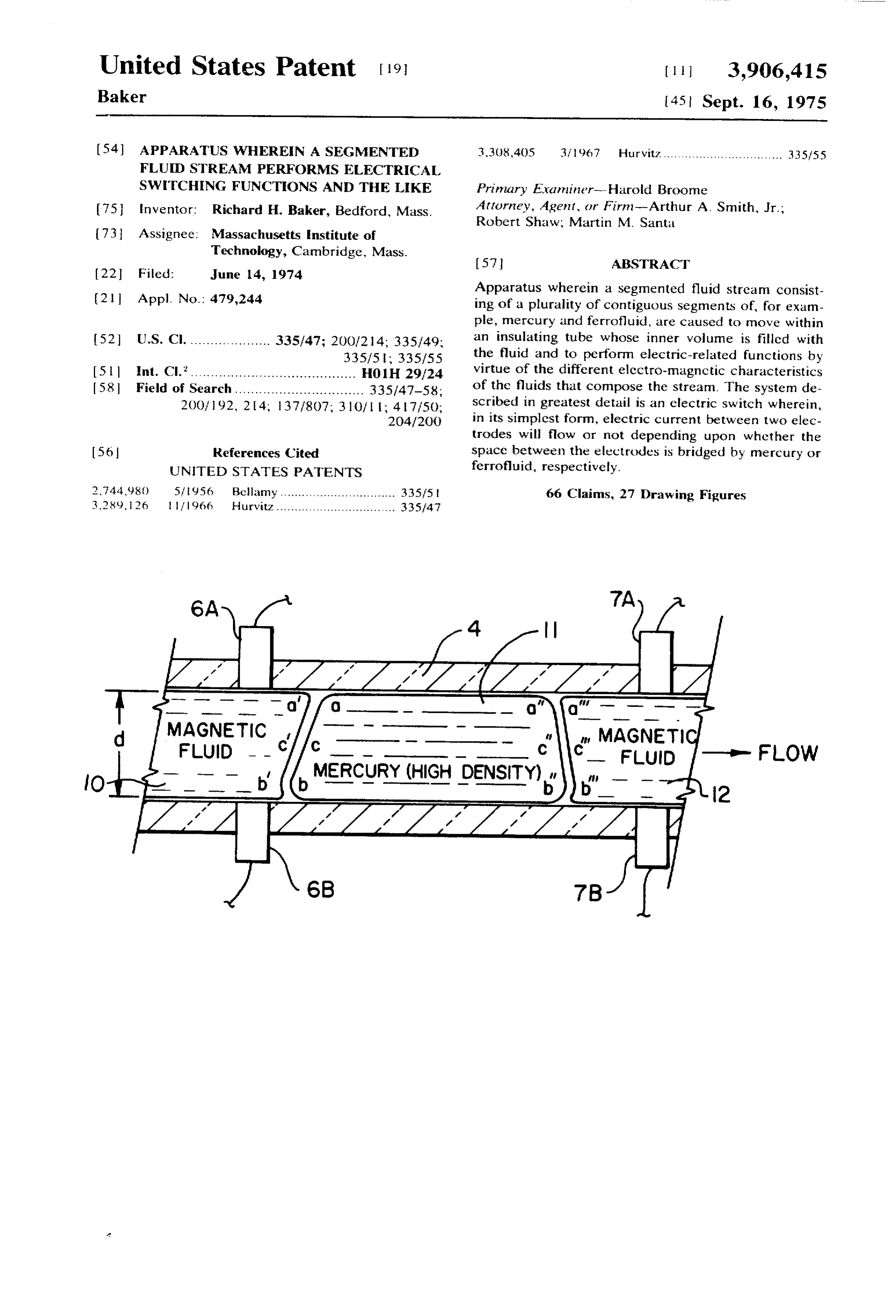
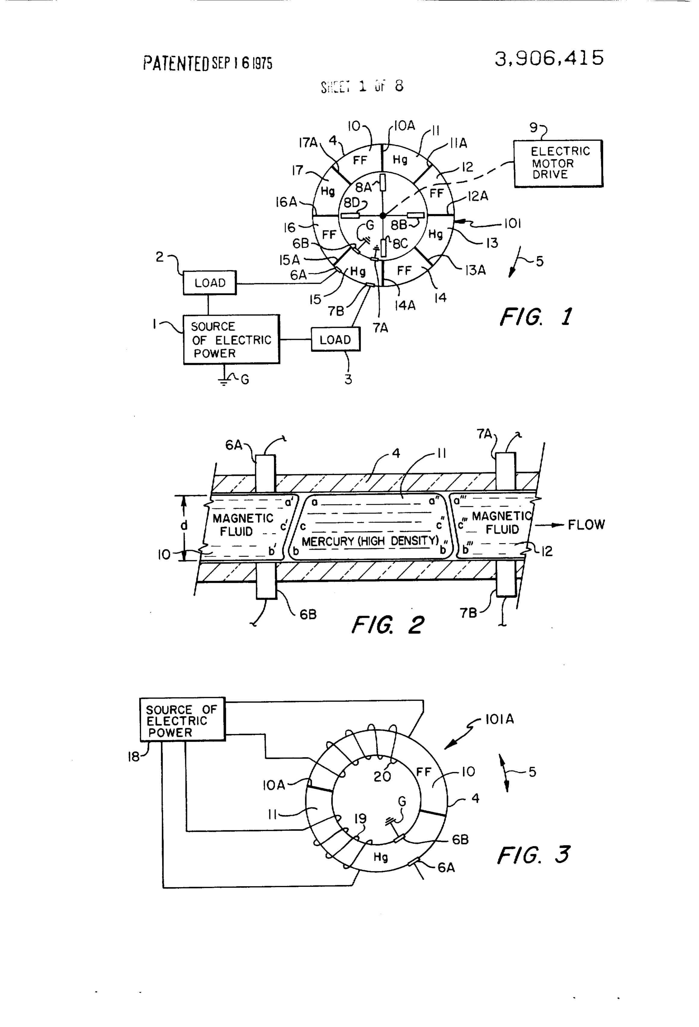
Since the ideal is not attainable, workers in the art have FIG. is a diagrammatic representation partly block strived toward the ideal situation. Mechanical switches diagram in form, of a fluid switch of the present inven have very favorable resistance characteristics but are tion comprising an annular tube within which flows in a relatively slow to operate, have wear problems, are ex circular path a plurality of segments of mercury (Hg) pensive to make, install and operate, and, particularly separated from one another by segments of a magnetic in high to very high voltages (38 kV and up), have 55 insulating fluid (marked FF for ferrofluid); arcing problems. Semiconductor devices, while fast FIG. 2 is a longitudinal section view, greatly en acting, are lossy, have electric current and voltage re larged, of a portion of the tube of FIG. 1 and shows a straints and, particularly in the case of thyristors, have segment of mercury with a partial segment of magnetic turn-off problems. Fluid switches such as, for example, fluid at either end thereof;
mercury tilt switches, have very good resistance char FIG. 3 is a schematic representation of a modifica acteristics, but are slow-acting and, for this and other tion of the switch of FIG. 1 showing only two of said reasons, have arcing problems. Other liquid switches segments and, whereas in FIG. 1 the segments are pro such as the electrocapillary type in the Lucien patent, pelled along a closedloop path around the tube by in are not so much switches as they are timers--the capil teraction between permanent magnets and the mag lary action upon which they depend acts that slowly. 65 netic fluid segments, in FIG. 3 two coils perform the Accordingly, it is an object of the present invention propulsion function;
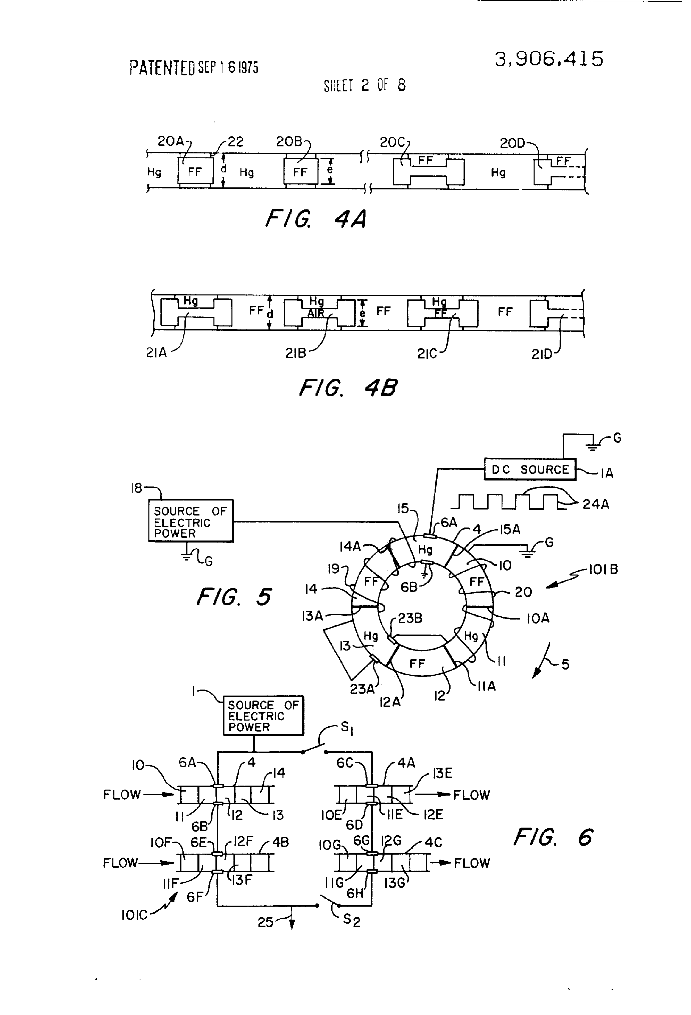
to provide a novel liquid switch that combines the fa FIGS. 4A and 4B show schematically mechanical vorable electrical resistance characteristics of mechan keepers for maintaining the integrity of the segments;
Page 11
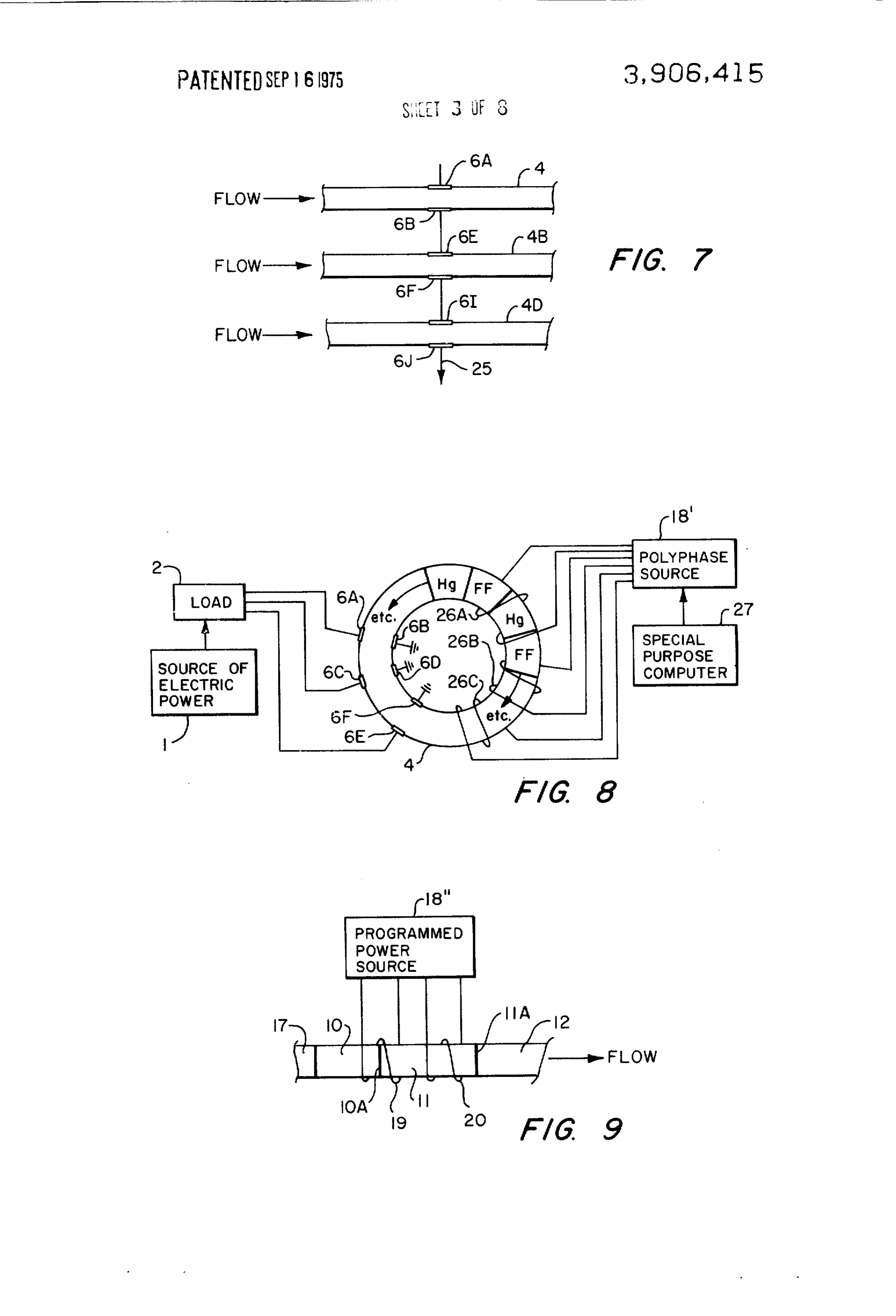
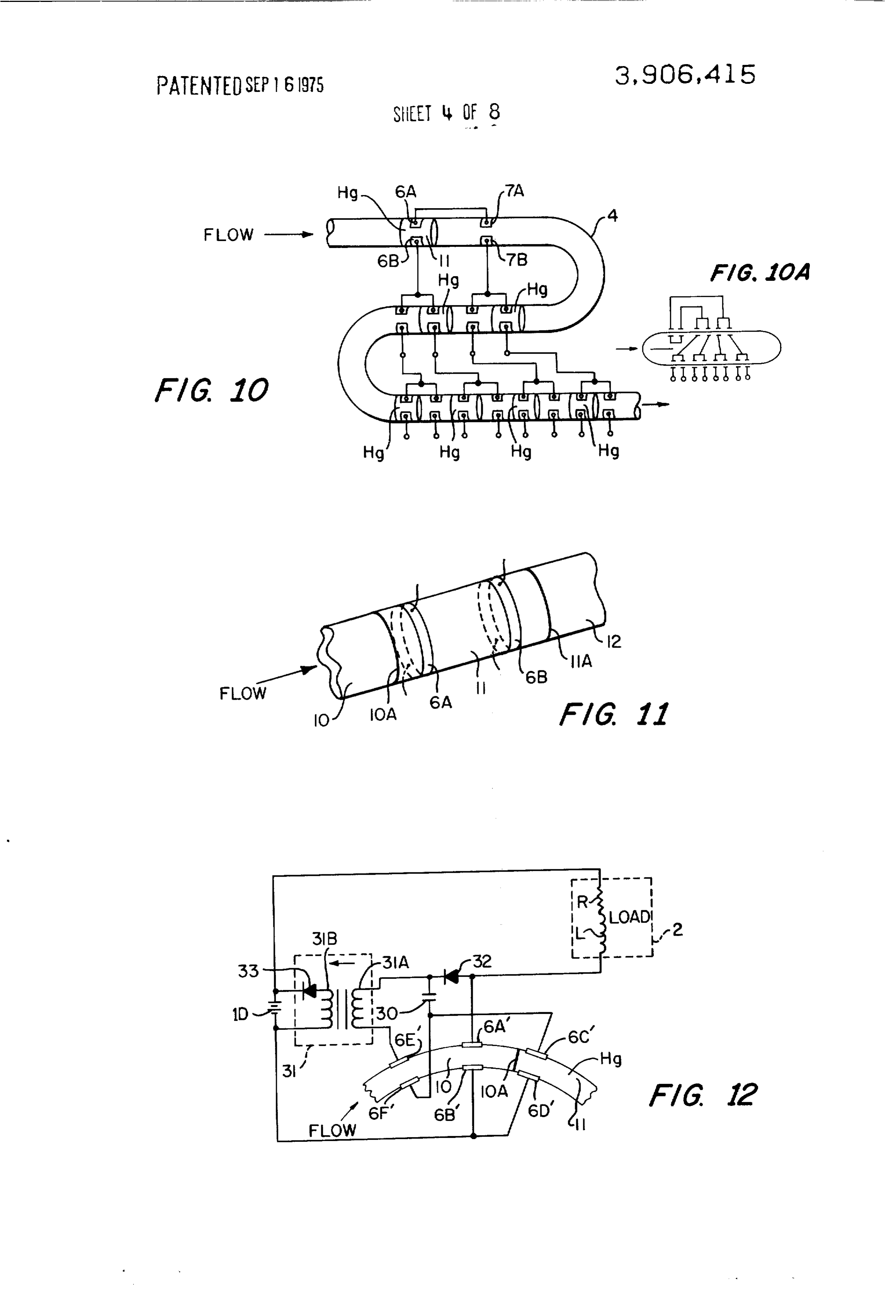
FIG. 5 shows schematically a modification of the tube 4 have respectively liquid electrical conducting switches shown in FIGS. and 3; material segments (e.g., mercury at the regions 11, 13, FIG. 6 shows schematically a portion of a composite 15, and 17) and fluid insulating material segments fluid switch wherein four tubes, segments and elec (e.g., magnetic fluid or ferrofluid comprising an electri trodes similar to the same elements in FIG. 1, are con cal insulator material such as transformer oil, for exam nected in a series/parallel arrangement to provide ple, and magnetic particles at the regions 10, 12, 14 AND/OR functions: and 16). The regions or segments 10, 11... are dis FIG. 7 is schematic of an extension of the AND-func posed axially or longitudinally along the tube 4 and, in tioning elements of FIG. 6; most situations of interest, in the form of a closed-loop FIG. 8 shows schematically a fluid switch in which O path. (In the description hereinafter, for simplicity of the segments are propelled in a circular path within a explanation, the elements 10-17 are always called tube by a polyphase magnetic field; 'segments," the conducting segments being mostly the FIG. 9 shows schematically a portion of a fluid switch liquid metal mercury and the insulating segments being in which propulsion is cffected by a magnetic field that mostly a liquid insulating magnetic fluid.) In order that is single phase or, the equivalent for present purposes, the apparatus 101 function in its required way, the a pulsed d-c field; transverse interfaces labeled 10A, 11A, 12A... between F.G. 10 shows schematically a portion of a fluid contiguous segments 10 and 11, 11 and 12, 12 and 13, switch with a single tube but miltiple split-ring elec etc., must be stable; in order that such stability exits, trodes, radially spaced; the liquid electrical conducting material and the fluid FIG. 10A shows the schematic of FIG. 10 symboli insulating material must be immiscible with respect to cally, one another, but further conditions must exist to pre FIG. 11 is an isometric schematic of a portion of a vent mixing of the two liquids. Later, there is a discus fluid switch in which the electrodes are axially-spaced sion of mechanical and magnetic keepers, but, for now, ring clectrodes; the means to prevent mixing is the combination of the FIG. 12 is a schematic representation of a d-c electric surface tensions of the mercury and the magnetic fluid system that includes a fluid switch (only partly shown) and the inner cross dimensions of the tube 4 (which is of the present invention having three electrode-pair assumed, for now, to have a circular cross section), as combinations that act in concert with the other circuit elements to reduce arcing in an operating switch; explained later with respect to FIG. 2, but there follows FIG. 12A shows schematically a system similar to 3O now a brief explanation of the further elements in FIG.
that shown in FIG. 12, except for a-c switching; The switch 101 includes a plurality of electrodes 6A, FIG. 13 is a schematic showing of a fluid switch to 6B, 7A, 7B that act in pair combinations. Thus, the show available electrode configurations;
FIGS. 14 and 15 show schematically possible loop electrodes 6A and 6B act together and 7A and 7B act patterns available when a plurality of loops are com together. The electrodes 6A and 6B of the pair combi bined to form a composite switcli; nation 6A-6B are disposed transversely across the tube FIG. 16 is a longitudinal section view, partly block from one another, as are, also, the electrodes 7A and diagram in form, of a portion of a fluid switch showing 7B of the pair combination 7A-7B, but that configura a mechanical mechanism for changing the lengths of tion is not always used, as later explained. The elec the segments, 40 trodes 6B and 7B are connected to ground G; ground in FIGS. 7, 18, 18A, 18B and 19 illustrate schemati this specification denotes a common or return conduc cally mechanisms for changing segment length, FIGS. to but can be actual earthing. The electrodes 6A, . . . 18A and 18B being enlarged and more detailed views , as shown in FIG. 2, are in contact with the mercury of a portion of FIG. 18; segments 1 1. . . . and with the magnetic insulating fluid FIG. 20 is a schematic representation of a fluid segments 10, . . . ; clectric current will flow between the switch which is switched ON and OFF by electro electrodes 6A and 6B (and 7A and 7B) when the gap mechanical means and which contains an overload therebetween is bridged by a mercury segment and cur switching mechanism thereby to permit its use as a d-c rent will be interrupted when the gap is filled with mag current circuit breaker in high-power and high-voltage netic insulating fluid. It should be noted that the axial systems; 5) length of the magnetic insulating fluid segments must FIG. 2 is a longitudinal section view, partly in block be greater than the axial length of the electrodes in the diagram form, of a fluid switch having one mercury seg electrical arrangement of FIG. 1. It should also be ment and one insulating fluid segment, the two being noted that the annular inner cavity of the tube 4 is com moved axially along the tube by a mechanical actuator pletely filled by the liquid segments, which is important that works against a spring force, the switch in FIG. 2, in that the circuit, when interrupted, is done so by fill like that of FIG. 20, being particularly useful in connec ing the gap with the liquid fluid insulator as interrup tion with high-power switching systems; and tion occurs, and such complete filling transmits axial FIG. 22 shows schematically a system capable of forces between the incompressible liquids. functions other than switch functions. The axial forces to effect axial flow of the segments In the detailed description that now follows, the in 6) 10, . . . in a stream around the closed-loop path within vention is discussed first in connection with the electric the tube 4, are provided by magnets 8A, 8B, 8C and 8D switch aspects thereof. Turning now to FIG. 1, there is whose magnetic fields couple to the segments 10, 12, shown at 101 a fluid switch for switching electric cur 14, and 16, respectively; and thereby move the seg rent between a source of electric power 1 and either of ments axially with respect to the electrodes in the di the loads labeled 2 and 3. The switch 101 comprises a 65 rection of the arrow numbered 5. At any instant all seg tube 4 of an electrically non-conductive material such ments 10 to 17 move in the same directional sense of as, for example, glass, plastic or ceramic. Contiguous flow, i.e., either clockwise or counterclockwise within regions 10, 11, 12, 13, 14, 15, 16 and 17 within the the tube 4. An electric motor 9 drives the magnets.
Page 12
S 6
The segments shown in FIG. 2 are accurate portray rial, particularly for low-voltage systems, to supply a als of a portion of an actual switch built and tested, the low resistance electrical connection therebetween. A switch being somewhat similar to that shown schemati further consideration is of great importance: the switch cally in FIG. 1. The cross dimensions designated d of of the present invention in almost all uses for which it the tube 4 must be small enough to permit surface ten is intended, must be capable of sharp, fast, make-break sion of the mercury and surface tension of the magnetic operations. Thus it is necessary that axial movement of fluid to retain both as segments within the tube. In the the liquid segments be fast and be effected only when actual switch, d is about 3 to 4 mm. It will be appreci the switch is actuated; it is necessary, therefore, that ated, therefore, that there is an upper limit on the d di the interior cross dimensions of the tube 4 be large mension, and, as noted elsewhere, there are constraints O enough to render insignificant axial forces due to capil on how small the cross dimensions of the tube 4 can be. lary action therein between the tube and either the In the fluid switch labeled 101A in FIG. 3, one seg mercury or the magnetic fluid. Such capillary action, if ment, the segment 10, of magnetic fluid is shown and it were present in sufficient amount, would retard axial one segment, the segment 11, of mercury, the interface flow of the segments, thereby increasing propulsion 5 problems, and would or could cause creep of the seg 10A there between being the only interface labeled. In
FIG. 3, and in later figures, elements that perform simi ments, thereby effecting a switching operation even in lar functions to that performed in the system of FIG. 1 the absence of an external propulsion force upon the generally are given the same or similar designations. segments.
Axial movement of the segments is effected by coils 19 Mention has been made of keepers to prevent mixing and 20 when the coils are energized by a d-c or other of the two liquids when, for example, the cross dimen power source 18 (see Baker U.S. Pat. No. 3,748,492), sions of the tube 4 exceed that which permits surface as now explained. At the time depicted in FIG. 3, cur tension alone to maintain the integrity of the segments. rent can flow between the electrodes 6A and 6B. The The permanent magnets 8A, 8B, . . . act as magnetic condition thereshown exists when the coil 20 is ener keepers since at all times a magnetic field couples to gized and the coil 19 is not. In that situation the seg 25 the segments 10, 12, 14, and 16, thereby giving those ment 10 of magnetic fluid will seek to position itself fluid segments a high apparent surface tension and the within the solenoidal coil 20. The segment 10 will tend semi-solid structure that magnetic fluids assume in the to center axially within the solenoidal coil 20. If the coil presence of a magnetic field. A small bias current 20 is de-energized and the coil 19 is energized, the seg through the coils 19 and 20 will also act as a magnetic ment 10 will travel axially in the direction of the arrow keeper; in this situation the switching current in the 5 to rest within the central opening of the solenoid 19, coils would be of much greater magnitude than the bias at which time electric current between the two elec current. Mechanical keepers are of greater importance trodes 6A and 6B is interrupted. The interruption time for present purposes because they allow the use of large can be quite fast as is discussed in said report, since, tubes with low drag and, thus, large liquid velocities, among other things, judicious placement of the various etc., a number of such keeper configurations is shown switch elements can result in a situation in which the in FIGS 4A and 4B.
interface between segments moves across the elec The mechanical keepers can be associated directly trodes fast enough to prevent initiation of an arc that with the magnetic fluid, as are the keepers labeled 20A, normally occurs when a circuit is interrupted (see FIG. 20B, 20O and 20D in FIG. 4A, or with the mercury, as 21 in said report). Thus, while the interface 10A in are the keepers labeled 21A, 21 B, 21C and 21 D in FIG. FIG. 2 can move either clockwise or counterclockwise, 4B. The bobbin-type keepers 21 A. . . . permit increas depending on relative positions of the coils 19 and 20 ing possibilities. For example, the keeper 21 B shows, and the length of the segment 10, it is possible to create schematically, a hollow keeper with air in the interior a situation wherein the interface 10A will always move 45 and 21C a keeper with magnetic fluid in the interior. In counterclockwise, thereby permitting it to build up this way, the weight of mercury can be somewhat bal substantial angular velocity before it crosses the clec anced with the weight of the a less massive fluid, which trodes 6A and 6B. In closing the circuit, the reverse sit tends to balance the system and reduce inertia. The uation will prevail, that is, fast segment velocity causes magnetic fluid can be contained within the keeper, as is the switch to close quickly. the case of the keepers 20A and 20B. Also, the latter It is above noted that the inside cross dimensions of 5) two keepers can have appropriate retentive magnetic the tube 4, in the embodiments so far described, must capability. In all the situations illustrated in FIGS 4A be small enough to permit surface tension of the two and 4B the interface, e.g., the interface numbered 22, liquids to retain both as discrete segments that fill the between the mercury and the magnetic fluid is sharp--a tube transversely, and the whole interior volume of the 55 requirement here. The cross dimension or dimensions tube is filled by the combined segments, that is, no air shown at e of the keepers must be sufficiently smaller gap exists therein. The latter situation is vital in the than the tube inner cross dimension or dimensions to case of very high voltage switching operations, but, maintain friction to acceptable limits, but it must be conceptually, the mercury segments can he separated sufficient to permit surface tension to maintain the in axially or longitudinally from one another by a gas 60 tegrity of the segments so that the cross space of the (e.g., air) for low voltage switching and mechanical tube is filled with either a segment of mercury or a seg axial propulsion used. It should he noted that the mag ment of magnetic fluid.
netic fluid is wetting as to the tube material (glass FIG. 2 shows the effect of gravity, the magnetic field here), and this is important to provide lubrication for exerting force on the ferrofluid, capillary forces and the mechanical keepers later discussed, but the liquid frictional drag, which all combine to set the shape of carrier of the magnetic fluid should be non-wetting as the boundary between the ferrofluid and the mercury. to the electrode material (which is silver or copper in The interface between the glass tube 4 and the mer the apparatus built so far). The mercury (or other con cury exhibits a characteristic non-wetting shape at ductive liquid) should be wetting of the electrode mate points b and b', while the oil-base magnetic fluid wets
Page 13
the glass at b' and b'. The static non-moving shape of trodes 6A-6B a train of electric pulses 24A is gener the mercury slug is basically a result of the balance be ated, consisting of voltage pulses from a d-c source 1A. tween the force due to its high surface tension and the The above discussion was of course simplified to force due to gravity. However, the slopes at the liquid demonstrate the idea. Like the commutator arrange interfaces bca and b'c'a' are both more nearly verti ment for a d-c motor, the angular displacement of con cal than one would expect because the magnetic field ducting-non-conducting segments is such that the increases the apparent surface tension of the magnet proper coils are energized in the proper time sequence fluid and causes it to approach the shape of a near-per for a net rotational torque to be applied to the liquid. fect cylinder. If the gravitational field were equal to 0, This action is the same as the combination of the brush the interface would be perpendicular to the tube axis. O and commutator segments in a d-c motor, which allow When the fluids are in motion there are frictional the proper armature coils to be energized in the proper losses (mostly in the mercury) caused by viscous ef time sequence such that a net rotational torque is ap fects and turbulence (note that in a practical situation plied to the armature.
mercury has only turbulent flow). The force exerted on In FIG. 6, it is assumed that the tubes shown at 4A, the slug of mercury by the magnetic fluid, together with 4B and 4C contain respectively, segments 10E, 11E . . the force due to surface tension and gravity, causes the , , 10F, 11F. . . , 10G, 11G . . . , that are like the seg magnetic fluid to displace (burrow under) the mercury ment 10, 11 . . . , respectively, that flow toward the at aa". Using a magnetic fluid with a higher permeabil right, as shown, to form a composite switch 101C. With ity in a stronger magnetic field will give it a higher ap switches S and S open, current (which can be a-c or parent surface tension, causing it to become rigid d-c) will flow from the source 1, through the electrode (semirigid) and, therefore, it can push against the mer 6A to the electrode 6B, thence to an electrode 6E and cury with less distortion per unit of force. (The seg a further electrode 6F to an output 25. The signal at the ments 10, 12, . . . are still considered fluid for purposes output 25 can be similar to the train of pulses 24A, but of this specification even in this rigid or semirigid state there is a difference. The electrodes 6A to 6F are in se particularly since ferrofluids will in fact flow even in 25 ries; thus the width of the pulses can be changed by ap this rigid or semirigid state.) This burrowing effect, propriate phasing of the segmented streams in the tubes along with the maximum permeability that can be ob 4 and 4B. The system acts as an AND gate. An OR tained, is related through a complex set of parameters. logic function can be provided by closing the switches The viscosity of the base fluid, fluid temperature, mag S and S and the pulse width can again be modified in netic doping material, and the size of the tube 4, etc. 30 a desired function. The OR function produces other used, all combine to set the maximum liquid velocity possibilities which are touched upon in the next para that can be obtained. Another parameter that limits the graph.
maximum fluid velocity is the physical size of the annu In FIG. 3 the switch 101A acts by an interchange of lus. Because the fluids are flowing in a circular path position of the segments 10 and 1, but essentially the segments, once positioned, remain so for periods of there is distortion of the liquid interface; the fluid at the smaller radius must flow at a greater velocity. Finally, time. The switch 101C in FIG. 6 can provide the same the frictional drag of liquids flowing in a pipe is in gen function as the switch 101A of FIG. 3 except that the eral a function of the roughness of the internal surface former has a continuously moving stream of segments. of the pipe and is proportional to the square of the ve Thus, for example, if the source 1 is d-c, current can locity and inversely proportional to the diameter (ID) 4) flow through the electrodes 6A to 6F and out or of the pipe. Obtaining a high liquid velocity is impor through the series of electrodes shown at 6C, 6D, 6G tant in many of the intended uses, and a more detailed and 6H and out; current can be interrupted by moving discussion of the parameters affecting this velocity is the relative positions of the segments so that one pair of given in said report. Based cn initial tests, however, it the series electrodes is always insulated from another appears that velocity up to 10 meters per second is (e.g., 6A is insulated from 6B; 6E is insulated from 6F, practical with an annulus of 10 cm diameter made with etc.). It will be appreciated that the open switch func 4 mm (ID) tubing. tion will require here very precise segment lengths. A simple electromagnetic means for propelling the This can be overcome by having a further tube 4D in segments 10, . . . in a closed-loop, circular path is illus FIG. 7, like the tubes 4 and 4B, with electrodes 6 and trated in the fluid switch shown at 101B in FIG. 5. The 5) 6.J. if each stream of segments is driven, say, by a vari switch 101B has, in addition to elements previously dis able frequency polyphase source such as that shown at cussed, electrodes 23A and 23B which serve as switch 18" in FIG. 8 and programmed appropriately by a spe ing electrodes for the coils 19 and 20. It is assumed at cial purpose computer 27, proper phasing can be ac the instant of time depicted in FIG. 5 that the circuit is complished. A simpler programing scheme, however, is energized by closing an ON-OFF switch in the source shown in FIG. 9 which shows the tube 4 only. (The 18. The source 18 is assumed to be, d-c although it closed-switch condition presents a similar-type prob need not be. Current will flow from the source, through lem, both conducting and non-conducting can be the coil 19, the switch or commutator 23A-23B, and solved, however, by having three of the electrode ar the coil 20 to ground G. (In this circumstance the seg rangements of FIG. 7 in parallel to form a three-part, ment 14 will be magnetized but will have no tendency series-parallel, AND/OR switch.) to move.) The interface 10A will tend to move clock in FIG. 9, the axial length of the segments is slightly wise with the geometry shown; the circuit between longer than the length of the solenoidal coils 19 and 20. contacts 23A-23B will open; and momentum will carry If the coil 19 at the instant depicted is energized by a the segment 11 to that now occupied by the segment programmed power source 18'' (see the Baker U.S. 13. The segment-stream propulsion circuit will be then Pat. No. 3,748,492 for a suitable low-power source for energized. In this way the stream of segments can be such purpose) the interface 10A will move to the right; propelled in a circular path; as alternate conducting now the coil 19 is de-energized and the coil 20 is ener and non-conducting segments move between the elec gized. Proper timing of electric current in the coils 19
Page 14
and 20 will establish the segment flow. Similar propul- filled with liquid segments, and by having insulating sion systems associated with the tubes 4A etc., establish segment or segments that consist of high dielectric the timing of the segments past the associated elec- strength oil (e.g., transformer oil). Also, arcing is re trodes. (The three-part series arrangement of FIG. 7 duced by the auxiliary electrical components in FIG. would, of course, also be used in combination with the 12, which interconnect and protect each pair combina tubes 4A and 4C to overcome the problem of the tion when current is switched, in the manner now dis length of the insulating segments, above noted, and the cussed.
three-part parallel arrangement would be used to over- In the system of FIG. 12, each segment of insulating come the same problem as to the conductive segments, fluid such as the segment 10, must have an axial length as also noted.) 10 greater than the axial length of the electrodes 6A". . . . Some further arrangements are shown in FIG. 10 ; in addition, each mercury segment, such as the seg which shows a single-tube ring relay tree; the mercury ment 11, normally has an axial length sufficient to span segments only are shown, the magnetic fluid insulating the electrode pairs, that is, the segment 11 must be long segments being implied. enough to short electrically the electrode pair 6A"-6B" In the embodiments discussed so far, the electrodes 15 to the pair 6E-6F' or 6A'-6B" to 6C'-6D". Both mer are disposed across the tube 4 from one another. It will cury segments and magnetic fluid insulating segments be appreciated that in the system of FIG. 10, the elec- may be long enough to span the axial distance between trodes 6A and 7B can be paired, for example, but that electrode pairs 6E-6F' and 6C'-6D'. Electrode posi in such case the mercury segments would have an axial tioning is such that the first electrode pair 6A-6B' is length sufficient to span the axial gap between the seg- 20 disposed, in axial location, between the second elec ments 6A and 7B; or some other interconnection trode pair 6C'-6D' and the third electrode pair scheme can be employed. Also, the electrodes so far 6E-6F', axial movement of the conductive and the in are curved plates, but they can be ring electrodes as sulating segments having the cffect, upon switching the shown schematically in FIG. 1 1 wherein the electrodes electric current, to time sequence the opening and clos 6A and 6B are axially displaced along the tube 4. 25 ing events of said electrode pairs. The opening and Whereas with the transverse electrode arrangement the closing events sequencing is shown in Table 1 below insulating segments must be greater in axial length than wherein the electrodes 6A-6B', 60'-6)' and 6E-6F' the electrode axial length (unless the AND arrange- are designated switch 1, switch 2, and switch 3, respcc ment of FIG. 7 is used), with an axial electrode dis- tively, and C and O mean closed and opened, respec placement, as later discussed, the mercury segments 30 tively.
TABLE
time - 1 Sequence -m-e-
Switch No. 2 3. 4 5 7 8. 9
1 C-O O-C C-O Ec 2 C-O O-C C-C)
must be sufficiently long to span the axial gap between The auxiliary components previously mentioned electrodes, but the axial length of the magnetic insulat- comprise a capacitance 30, a transformer 3 and a ing fluid segments need not. It might further be pointed diode 32. The primary, labeled 31 A. of the transformer out at this juncture that by having different-length seg- is connected in series with the electrodes of the third ments in either electrode configuration, the pulse width electrode pair 6E-6F' and the combination thereof is of the pulses 24A in FIG. 5 can vary from one another-- 5 connected in parallel with the capacitance 30, as -and, as mentioned, that width can be varied. By way of shown. The anode of the diode 32 is connected to the example, it should be appreciated that by varying the positive side of the first electrode pair 6A-6B', that is, lengths of the mercury segments then, makebefore- to the electrode 6A', and the cathode side of the diode break (long segments) and break-before-make (short 32 is connected to one terminal of the capacitance and segments) switching action can be obtained. This fur- 50 thence being connected through the second electrode ther demonstrates the flexibility of this invention. pair 6C'-6D' to the negative side of the first electrode In the system of FIG. 12, a source of d-c power D pair as well as to the negative side of the source 1D. energizes the load 2 through a liquid switch that com- The transformer secondary labeled 31B, is intercon prises a plurality of electrode pairs 6A" and 6B', 6G' nected through a further diode 33 back to the source and 6D', and 6E' and 6F', which acts as pair combina- 3 ID of d-c current, thereby to allow energy stored in the tions to perform switching functions. The load current capacitance 30 to be returned to the source as a normal flow is normally between one electrode of the pair part of the Switching operation. In this way, the energy (e.g., the electrode 6A") and the other electrode of the stored in the arc-protecting capacitance 30 is not pair (e.g., the electrode 6B') and occurs when a mer- wasted (dissipated) but instead returns to the d-c cury segment is disposed between the pair combina- 60 source 1D.
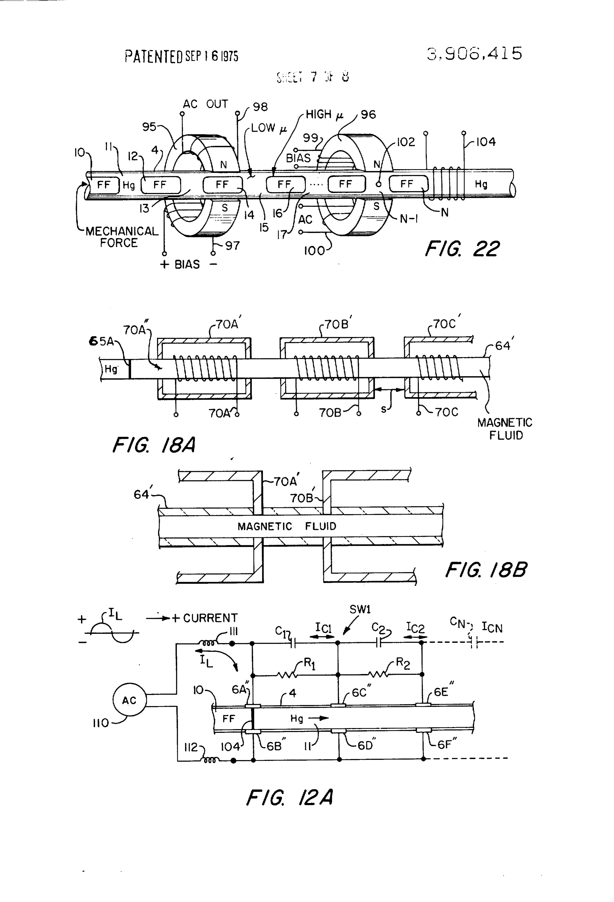
tion. The switching arrangement of FIG. 12 is for a d-c The switching system of FIG. 12 is intended for arc- power system. A modification can be made for a-e less switching of d-c power systems. Thus, the first elec- power systems, as shown in FIG. 12A wherein an a-c trode pair 6A"-6B', the second electrode pair 60-6D', power source 110 feeds inductive loads 111 and 1 12. A and the third electrode pair 6E-6F' are subject to arc- 65 load current It passes between electrodes 6A' and 6B'' ing which is minimized by having the fluid segments when the gap therebetween is bridged by mercury and move axially past the electrodes at a high angular ve- the load current it is interrupted when the gap is filled locity, by having the whole inner volume of the tube with an insulating liquid segment. To reduce or mini
Page 15
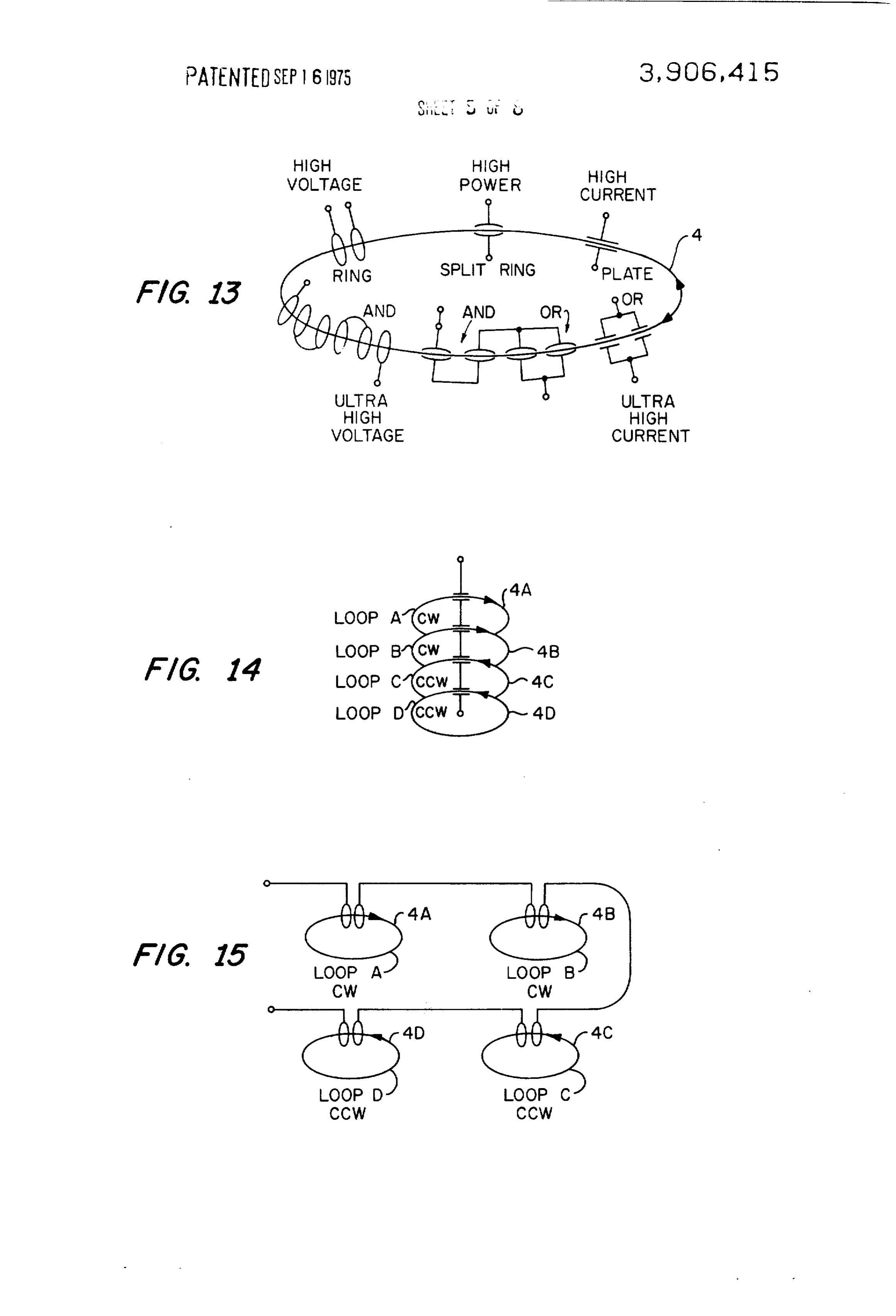
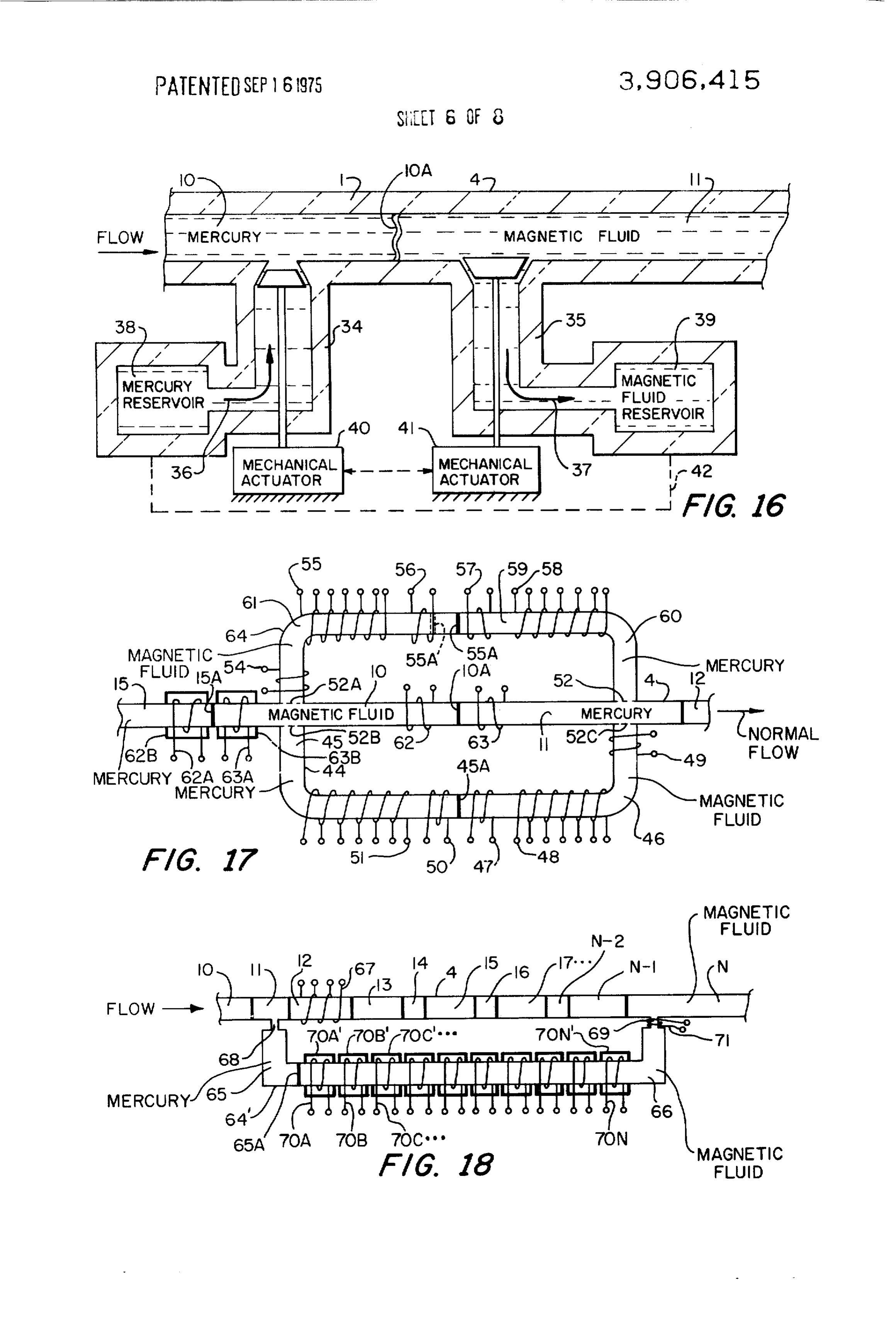
mize arcing, further circuit elements, capacitances C, Another scheme for changing segment length is C. . . . , resistances R. R. . . . , and electrode pairs 6CA shown in FIG. 17 wherein it is assumed for now that the '-6D'' . . . and 6E'-6F'" . . . are used. The capacitance normal (i.e., in normal switching operation) segment C>Co. . . . . When the electrodes 6A' and 6B' are flow is to the right. In FIG. 17, as is later noted in some shorted by mercury, the other circuit elements C, etc., 5 detail, coils 62A and 63A perform liquid gating func are effectively out of the system since there is almost no tions, coils 62 and 63 perform liquid motoring func voltage drop between the electrodes. Now, however, if tions, coils 56, 57, etc., associated with upper reservoir an insulating liquid segment entering from the left-hand tube 64 perform liquid gating functions, in connection side fills the gap between the electrodes 6A'' and 6B', with the reservoir tube 64 and coils 47, 48, etc., per a current I flows into the capacitance C and through form a liquid gating function in connection with lower the electrodes 6C'' and 6 D'' (it is assumed that the reservoir tube 44. The liquid gating function is dis load waveform, also designated in FIG. 12A, is +). cussed later in connection with FIGS. 18, 18A and 18B, Since electrodes 6C'' and 6 D'' are still shorted little but, essentially, the coils 62A and 63A act to stop the current will flow to the capacitance C. Now the insu flow of segments in the main tube 4. In the circum lating segment is made to isolate both 6A" and 6C'' stance depicted in FIG. 17 the mercurymagnetic fluid from 6B' and 6D'', respectively. A current I will flow interface 15A, in a condition of normal flow, is leaving into the capacitance C (since CDC, 1 will be much the inner space of the solenoidal coil 62A. If now the smaller than was l), and so forth, for further elec coil 63A is energized, the mercury-magnetic fluid inter trode-capacitance combinations. It should be seen that face will be stopped at the left-hand end of the coil 1. DID > . . . . Since the fluid segments stream is 63A. lt will be appreciated that if the coil 62A, rather moving rapidly, whether impelled by the electromag than the coil 63A had been energized, that the inter netic drive of FIG. 3 or the later-discussed mechanical actuator of FIG. 21, for example, the time frame of face 15A would have been stopped by the coil 62A. events is small. The resistances R. R. . . . act to dissi (Also, the coils 62A and 63A can apply motor forces to pate energy stored in the capacitances C, C, . . . in 25 the segments by proper sequencing.) In order to make the effect of the coils 62A and 63 A sharp, low reluc preparation for circuit reclosure and then subsequent tance paths around the solenoidal coils is provided by circuit interruption. If the load current It is negative at mu-metal the time of interruption, the same sequence of events spectively. orIn other this magnetic circuits 62B and 63B, re connection, all the coils in FIG. 17 will occur except that the direction of current flow is would normally be provided with such magnetic cir reversed and C, C2, . . . will charge to the opposite po 3) larities. cuits but such is not shown in FIG. 17 to reduce clutter Before going into a further detailed discussion of fur ing of an already cluttered figure. Further coils, like ther modifications of the invention, a brief review of 62A and 63A, can be placed around the tube 4 to stop the various switching possibilities is made with refer flow in a situation when normal flow is to the left. Here ence to FIGS. 13, 14, and 15 which, in view of the pre 3. 5 and in other situations discussed in this specification, vious explanation, are largely self-explanatory. In FIG. the further possibilities of the concepts shown are 13 the single closed-loop tube 4 has associated with it many, but, generally, exemplary systems only are different contact configurations and interconnecting shown.
patterns to supply the purposes or functions indicated. Changing the lengths of segments 10 and 11 is ac The arrows indicate flow of the segment stream, which 4) complished by withdrawing one fluid from one of the can be clockwise (CW) or counterclockwise (CCW). reservoir tubes 44 or 64 and by simultaneously adding Two loop patterns are shown in FIGS. 14 and 15 a like amount of the other fluid (in some circumstances wherein the tubes are designated 4A to 4D. it can be the same fluid from some axially displaced Mention is made above of changing the effective segment) to one of the reservoir tubes. The particular lengths of the segments by employing AND/OR config 45 reservoir tube employed will depend on the particular urations; it will be appreciated with reference to FIGS. Segment positioning at the time of fluid transfer. As 14 and 15, that changes in the angular velocity of the suming now the situation of FIG. 17, if the coil 62 is de fluid in the tubes 4A, etc., relative to one another can energized and the coil 63 is energized a force will be ex change the effective lengths of the segments as re erted on the fluid in the tube 4 tending to move the flected in the pulse width of the output. (Together magnetic fluid-mercury interface 10A into the interior FIGS. 13, 14 and 15 demonstrate the flexibility of the of the coil 63, that is, to the right. It is intended here possible switching combinations and configurations.) that the segment 10 in FIG. 17 be increased in length Actual changes in segment lengths can be made as now and the segment 11 be decreased. To do this magnetic explained with reference to FIGS. 16, 17, 18, 8A, 18B fluid 61 in the tube 64 is allowed to flow into the tube and 9. 4 and mercury from the segment 1 1 is allowed to flow In FIG. 16, valved inlets 34 and 35 to the tube 4 per into reservoir mercury 60 in the tube 64. Interchange mit simultaneous introduction and removal of either of flow between the main tube and the reservoir tube is mercury or magnetic fluid; that is, when one fluid seg affected by a number of elements. Thus, small mesh ment is reduced in size, another must be increased ( - one to two mils) screens 52, 52A, 52B and 52C pre since the tube 4 is filled with incompressible fluids. Ar 6) vent flow of mercury into magnetic fluid because of rows 36 and 37 indicate that the flow is from a reservoir surface tension of the mercury; similarly when coils 49 38 of mercury to the tube 4 and from the tube 4 to a and 54 are energized the increase of apparent surface magnetic fluid reservoir 39. Mechanical actuators 40 tension in the magnetic fluid prevents flow of magnetic and 41 move the valves; the dotted line 42 between the fluid through screens 52C and 52A, respectively, to a reservoirs 38 and 39 indicates interaction so that a mercury Segment. In either situation, however, mer pressure head is created in the reservoir 38 at the same cury will pass through the screen at a mercury-mercury time as a reduced pressure is created in the reservoir interface and magnetic fluid will pass through a screen 39. at a magnetic fluid-magnetic fluid interface.
Page 16
If now in FIG. 17 the coil 49 is energized and the coil netic fluid 66 which tends to flow into the magnetic 56 is energized (coils 54, 55, 57,58, 59 associated with fluid segment N. The amount of mercury flow is deter the upper tube 64 are de-energized and coils 47, 48, 50 mined by energizing appropriate Solenoidal coils 70A, and 51 associated with the lower tube are de-ener 70B . . . 70N, as before. The amount of mercury that gized), the interface 10A will move to the right (and 5 flows out of the segment 11 in the tube 4 is equalled by 55A will move to the left, as later noted). The segments magnetic fluid that flows into the magnetic fluid seg in the closed-loop main tube cannot circulate because ment N through an orifice 69. The orifice 68 acts like they are stopped (i.e., maintained in a stable or fixed a valve for mercury in that when a 1 to 2 mm orifice is axial position) by the energized coil 63A; mercury of used surface tension of mercury prevents mercury flow the segment 1 1 cannot move into the tube 44 because () therethrough when magnetic fluid is on one side of the it is stopped by the screen 52C, and it is further stopped orifice and mercury on the other; when mercury ap by the energized coil 49 which acts to gate flow in the pears on both sides, there is free flow. The orifice 69 other direction at the time depicted; so the combina will prevent flow of mercury from the main tube 4 into tion prevents flow from the magnetic fluid reservoir the reservoir 66 of magnetic fluid. A coil 71, when en shown at 46 or the mercury reservoir showing at 45, to ergized, also acts in the same manner, that is, it acts to the main tube 4. In this circumstance the magnetic prevent the flow of mercury into the reservoir 66; this fluid-mercury interface labeled 55A will move to the is because the magnetic fluid resists leaving the volume left to about the dotted position of 55A shown. The inside the coil 71. To prevent opposite flow, that is, summary of events are these: the coil 63A is energized, flow of magnetic fluid through the orifice 69 into the the coil 63 is energized, and the coil 56 is energized; mercury in the main tube 4, it is necessary to prevent mercury flows from the segment 11, through the screen flow into the mercury reservoir 65 through the orifice 52 to the reservoir 60; and magnetic fluid flows from 68. This is effected by stopping movement of the inter the reservoir 61, through the screen 52A to the seg face labeled 65A to the right in FIG. 18 by energizing ment 10. The segment 10 in FIG. 17 is thereby made 25 an appropriate coil of the coils 70A. . . . 70N. larger and the segment 1 1 shorter. If at some later time Mention is made above of the lower reluctance mag the segment positions in the main tube 4 are changed so netic circuits 62B and 63B. Similar low reluctance cir that the segment 10 and 11 are replaced by the seg cuits are shown in FIGS. 18, 18A and 18B where they ments 15 and 10, respectively, mercury can be taken are labeled 70A., 70B' . . . and each is associated with from the reservoir 45 and added to the mercury seg a solenoidal coil 70A, 70B . . . , respectively, that re ment 15 while the segment 10 is discharging to the res ceives the non-magnetic tube 64' If the coil 67 is ener ervoir 46. In normal operation the coils 49 and 54 are gized, as before, and any or all the coils 70A., 70B . . . energized, but there may be situations in which they are are energized, the mercury-magnetic fluid interface (t. marked 65A will stop at the left end of the coil 70A. It is in order at this juncture to discuss the gating More particularly, since, as shown best in FIG. 18B, the function mentioned above, again with reference to 35 magnetic circuits 70A', 70B' . . . , pass through the wall FIG. 17. It will be recalled that with the normal seg of the tube 64" to be in physical contact with the mag ment flow to the right, the interface 15A will be netic fluid therein, the interface 65A will stop in the stopped at the left-end of the coil 63A. If, now, the nor axial region designated 70A' in FIG. 18A. The amount mal flow of segments in the tube 4 is reversed and the of change in the lengths of the segments 1 and N is de coil 62 energized, the interface 10A will stop at the 4) termined here by the position finally taken by that in right side of the solenoid coil 62. Coils like the coils terface 65A and that position can be progressively 62A and 63 A can be placed, like 62A and 63 A, outside moved to the right in FIG. 18 by, for example, starting the right-hand side of the reservoir area. Indeed, a sin with all the coils 70A. . . . 70N energized and succes gle coil at an appropriate location will suffice. It should 45 sively de-energizing the coils, beginning with the coil be seen at this juncture that a segment of magnetic fluid 70A.
tries to fill the interior of an energized solenoid coil: if It would unduly prolong this specification to detail an attempt is made to reduce the volume within the en the possibilities implied in the situations depicted in ergized solenoid, that is occupied by the magnetic fluid, FIGS. 17 and 18, but a few comments in this respect the electromagnetic forces engendered resist the are in order. If the segments 10, 11, . . . in FIG. 18, for change. (Similarly, in motor action the electromagnetic example, serve to program events in a communication forces cause the required position change in appropri system, that program can be changed by modifying the ate circumstances.) In the system of FIG. 17 there are lengths of the segments; such modification can be ac what might be termed mechanical gates 52, 52A . . . . complished by computer control of the various pro electro-mechanical gates 52, 52C and coils 54 and 49 gram coils such as the coils 67, 70A. . . and 71 in FIG. in combination, and electromagnetic gates (e.g., the 18. In a system there can be many tubes like the tube coils 62 64 with associated elements. Such tubes can contain A further ramification of the concept just described multiple mercury and magnetic fluid segments to give is illustrated in FIG. 18 wherein, again, segment flow in the necessary proper interface for liquid gating. And the tube 4 is toward the right. The segments are un the functions of the coils 62 and 63 and 62A and 63A equal in length, and it is assumed continue beyond the can be introduced to the system of FIG. 18. segment 17 to some indefinite number N, a segment of The system of FIG. 19 permits simultaneous changes mercury being always separated by a segment of mag in lengths of two mercury segments or two magnetic fluid segments. If at the time depicted in FIG. 19, coils netic fluid and vice versa. If at the instant depicted in
FIG. 18, the coil shown at 67 is energized, then the 65 75' and 76' are energized and a force is applied as fluid segment 12 (which is magnetic fluid) will tend to shown to a bellows 77 filled with magnetic fluid, there stay where it is and mercury from the segment 1 1 will will be a flow of fluid into the segment 10 and from the tend to flow through an orifice 68 into the mercury sec Segment 12 into a bellows 78. At some other time when tion 65 of a tube 64". The tube 64' also contains mag the positions of the segments of magnetic fluid and
Page 17
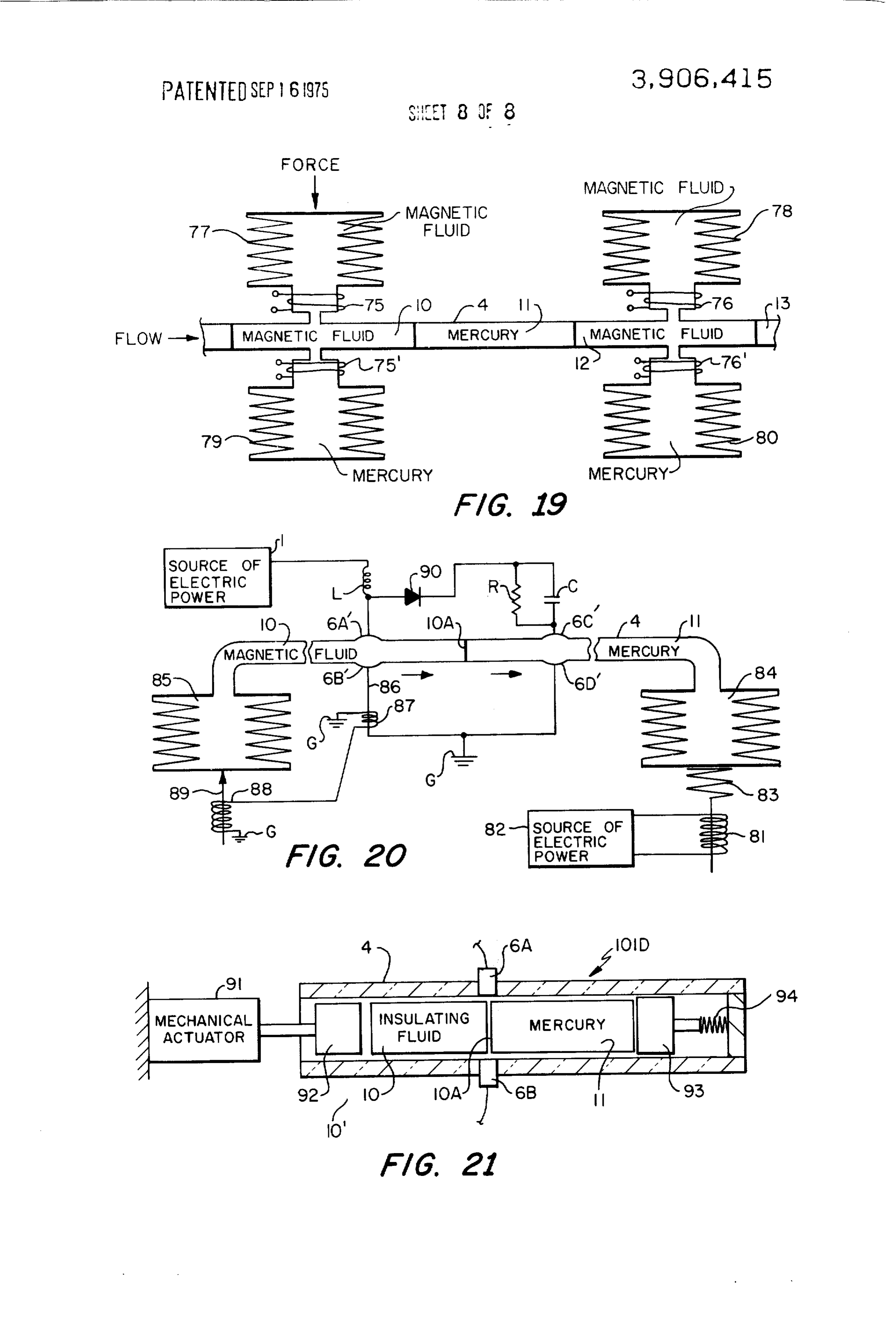
mercury are interchanged by a flow of the liquid stream In FIG. 22 the internal volume in the tube 4 again is to the right, for example, then interchange of mercury filled with magnetic segments 10, 12, . . . N. etc. can be effected by use of bellows 79 and 80. In the lat (marked FF for ferro-fluid) separated by mercury seg ter situations coils 75 and 76 are energized as a gate to ments 11, 12, ... N-1, etc. A mechanical or other force prevent magnetic fluid from entering the mercury seg moves the segments to the right; the tube in FIG. 22 ments. To provide good magnetic coupling, the coils can form a closed-loop path. The mercury segments 75, 76, 75' and 76' would be wound around the orifice with low permeability and the magnetic fluid segment between the bellows and the tube 4, not the bellows, as with high permeability move past magnetic circuits 95 shown: and low reluctance shields as shown in FIG. 18 and 96 external to the tube 4, except for the pole pieces can when necessary be employed to increase the mag O marked N and S in each case, the pole pieces (or, more netic coupling to the magnetic fluid. accurately, the pole faces) being preferably in physical Bellows can also be employed to propel the fluid axi contact with the high permeability magnetic segments ally past the electrodes, as is shown in FIG. 20. To ener 10, 12, ... (and, thus, of course, the low permeability gize a load L, the coil 81 of a solenoid is energized by segments 11, 13, . . . ). A d-c bias current in a coil 97 an electric source 82, force being transmitted upward 5 will result in an a-c voltage out of a coil 98; similarly, an through a spring 83 to bellows 84 filled with mercury. a-c bias on a coil 99 will result in a modulated a-c cur The bellows 84 compresses causing the interface 10A rent out of a coil 100. Further, if a current I is passed to move to the left, thereby permitting current to flow through the mercury segment shown at N-1 which is from the source 1 through the load L and electrodes subjected to a magnetic field intensity B, there is a 6A' and 6B" to ground G. Insulating fluid in the figure force on the segment N-1, f = I X B. In this way a moves into a bellows 85 that has appropriate mechani propulsion force can be applied to the segment N-1 cal biasing. In the event of a fault on the system of FIG. and thence to the other segments. The current is intro 20, a high fault current in the conductor numbered 86 duced through an electrode not shown, and removed is picked up by a coil 87 which energizes a coil 88 that through the electrode shown at 102. If this current I forces upward a plunger 89. The plunger 89 overcomes 25 from the electrode 102 is connected to flow through a the mechanical bias on the bellows 85, thereby forcing Solenoid 104, then the magnetic segment N will be insulating fluid (e.g., transformer oil or the like) into pulled under the solenoid 104. In this way both the the tube 4 and the interface 10A to the right. Mercury mercury segment N-1 and the magnetic fluid segment moves into the bellows 84 overcoming the mechanical N are pumped simultaneously. The simultaneous bias therein provided by the spring 83. In this way the 3) pumping of both kinds of segments can be termed 'du circuit to the load will open and, if the source 82 is de al-phase pumping'. This dual-phase multisegment energized, will remain open. The electrodes 6A", 6B', pumping can be extended by adding more stages. 6C and 6D' function somewhat similarly to their oper A few additional remarks of a general nature are con ation in FIG 2 in that the two extra electrodes serve tained in this paragraph. The previous discussion, for to reduce arcing. Thus, for example when the load cir simplicity of explanation, is directed to a multi-seg cuit is opened by first isolating the electrodes 6A-6B" mented-fluid apparatus wherein a stream of mercury in FIG. 20, the inductive load L feeds into a capaci and magnetic fluid segments flow within a glass tube, tance C during interruption of current flow between circular in cross dimensions. It should be noted: that the electrodes 6A" and 6B". A resistance R serves to the conductive liquids other than mercury can, and dissipate energy stored by the capacitance C and re 40 Often preferably should (depending upon the use), be verse flow is prevented by a diode 90. It will be appreci used (e.g., Cerrlow-117 alloy a tin eutectic); that the ated that the arrangement of FIG. 20 is best adapted for magnetic fluids need not always be ferrofluids, i.e., the d-c, but the liquid switch thereshown is useful for a-c as particles within the fluid carrier can be larger than well (FIG. 2A). those found in ferrofluids, for example; that elliptical or The fluid switch shown at 10 D in FG. 21 is sonne Other cross dimensions can be employed for the tubes; what similar to the switch in F.G. 20 in that a mechani that the tube material need not be insulating in connec cal actuator, the actuator marked 91, moves the seg tion with some functions (e.g., pumping); that the ments 10 and 11 (there can be more) toward the right, course traveled by the fluid stream in apparatus opera axially past the electrodes 6A and 6B (there can be tion can vary from the various shapes shown, etc. The more). The actuator 91, which can be air, hydraulic, term “tube' is used throughout herein to denote any etc., moves a piston 92 to the right; a piston 93 under member having an elongate chamber, channel or duct biasing influence of a spring 94 applies a force toward within which the fluid segments can move in the same the left in FIG. 21, upon the segments. It will be appre directional sense. These and still further modifications ciated that an electromagnetic force to the left upon will occur to persons skilled in the art and all such mod the fluid segments 10, 11, etc., in FIG. 21 will exert a 5 5 ifications are deemed to be within the spirit and scope force to the left upon the piston 92 in which case the of the invention as defined by the appended claims. system of FIG. 21 acts as an actuator in which an elec What is claimed is:
tromagnetic force is converted to a mechanical force 1. A fluid switch for switching electric current that through the piston 92; the function in such system can comprises, in combination:
be characterized as a motor or pump function with the 6) a tube of an electrically non-conductive material, piston 92 serving as a link to some outside load. It can contiguous regions within the tube having respec be seen that the tube 4 in the apparatus 101D can be tively a liquid electrical conducting material and a millimeters across, there can be many, many such fluid insulating material, said regions being dis tubes, the segments 10, 1 etc., in each tube can be ac posed axially along the tube, there being a stable tuated by coils in the manner discussed previously in 65 transverse interface between the two materials at connection with FIGS. 5 and 8, for example, thereby to said regions;
provide a plurality of fluid actuators, all individually a plurality of electrodes in contact with the liquid controllable to very accurate force levels. electrical conducting material und the fluid insulat
Page 18
ing material; and 9. A fluid switch as claimed in claim 7 in which fluid means for propelling the liquid electrically conduct insulating material is a magnetic liquid and in which the ing material and the fluid insulating material to electromagnetic means comprises solenoid means cause the liquid electrical conducting material and which, when energized, provides a magnetic field mag the fluid insulating material to move axially relative netically coupled to the magnetic liquid. to the electrodes, thereby to permit electric cur 10. A fluid switch as claimed in claim 1 in which the rents to flow between the electrodes and to be in tube is a closed-loop tube wherein the liquid electrical terrupted depending upon whether the liquid elec conducting material and the fluid insulating material trical conducting material or the fluid insulating move axially in an endless closed-loop path. material, respectively, is positioned between the O 11. A fluid switch as claimed in claim 10 in which the electrodes, the axial movement of the liquid elec fluid insulating material is a liquid and in which the trical conducting material and the fluid insulating whole internal volume of the tube is filled with the material being always in the same directional sense combination of the liquid electrical conducting mate of flow; the interior cross dimensions of the tube rial and the liquid insulating material. being large enough to render insignificant axial 5 12. A fluid switch as claimed in claim 1 in which the forces due to capillary action therein between the plurality of electrodes comprises a plurality of elec tube and either the liquid electrical conducting ma trode pairs which act as pair combinations, electric cur terial or the fluid insulating material. rent flow being between one electrode of the pair and 2. A fluid switch as claimed in claim 1 in which the the other electrode of the pair when the liquid electri liquid electrical conducting material is mercury, in 20 cal conducting material is disposed between a pair which the fluid insulating material is a magnetic fluid, combination, said plurality of electrode pairs being po and in which the means for propelling comprises means sitioned axially along the tube, and in which said means for creating magnetic fields at locations along the tube for propelling is operable to effect said axial movement displaced axially from one another, said fields being but is adapted as well to maintain stable axial position magnetically coupled with the magnetic fluid, electro 25 ing of the liquid electrical conducting material and the magnetic interaction between the magnetic fluid and fluid insulating material.
the magnetic field serving to effect said axial movement 13. A fluid switch as claimed in claim in which the and serving as well to stop said axial movement at pre liquid electrical conducting material is in the form of a determined axial regions, thereby to position the mer segment and in which the fluid insulating material is cury and the magnetic fluid axially within the tube. 30 also in the form of a segment, the segment of the liquid 3. A fluid switch as claimed in claim 1 in which the electrical conducting material being axially contiguous liquid electrical conducting material is a liquid metal to the segment of the fluid insulating material, both ma segment, in which the fluid insulating material is a liq terial segments being axially movable relative to said uid insulating material segment and in which the means 35 electrodes, and in which said means for propelling is for propelling is adapted as well to maintain the seg adapted to maintain axial positioning of said segments. ments in stable axial positions. 14. A fluid switch as claimed in claim 13 comprising 4. A fluid switch as claimed in claim 3 in which a plurality of segments of liquid electrical conducting means is provided to prevent mixing of the liquid metal material, each being separated from the other by a seg and the liquid insulating material. ment of fluid insulating material.
5. A fluid switch as claimed in claim 4 in which the 40 15. A fluid switch as claimed in claim 14 in which the means to prevent mixing is a tube having inside cross lengths of at least some of the segments of either the dimensions small enough to permit surface tension of liquid electrical conducting material or the fluid insu the liquid metal and surface tension of the liquid insu lating material differ from one another. lating material to retain both as segments within the 16. A fluid switch as claimed in claim 15 in which the tube. 45 segment lengths are alterable and in which means is 6. A fluid switch as claimed in claim 1 in which the provided to alter said segment lengths in situ. means for propelling comprises mechanical means to 17. A fluid switch as claimed in claim 14 in which the impart an axial force to at least one of the liquid electri plurality of electrodes comprises a plurality of elec cal conducting material and the fluid insulating mate trode pairs which act as pair combinations, electric cir rial, said axial force acting to effect propulsion of the 50 cuit flow being between one electrode of the pair and electrical conducting material and the fluid insulating the other electrode of the pair when the liquid electri material axially along the tube as well as to establish cal conducting material is disposed between a pair stable axial positions for the same along the tube. combination, said plurality of electrode pairs being po 7. A fluid switch as claimed in claim 1 in which the sitioned axially along the tube.
means for propelling comprises electromagnetic means 55 18. A fluid switch as claimed in claim 13 in which the operable to impart an axial force to at least one of the plurality of electrodes comprises a plurality of elec liquid electrical conducting material and the fluid insu trode pairs which acts as pair combinations, said com lating material, said axial force acting to effect propul binations being electrically interconnected through sion of the electrical conducting material and the fluid auxiliary energy storage component means that acts, insulating material axially along the tube as well as to 60 during switching, to arrest arcing so that each pair com establish stable axial positions for the same along the bination is protected from electrical arcing when cur tube. rent is switched, the electrodes of each pair combina 8. A fluid switch as claimed in claim 7 in which the tion being disposed transversely across the tube from fluid insulating material is a magnetic liquid and in one another.
which the electromagnetic means comprises perma 65 19. A fluid switch as claimed in claim 18 in which the nent magnet means magnetically coupled to the mag fluid insulating material comprises a high dielectric netic fluid and having means to move the permanent strength oil in which there are a first electrode pair, a magnet means axially relative to the tube. second electrode pair and a third electrode pair dis
Page 19
placed axially from one another along the tube, and in sufficiently smaller than the inner cross dimensions of which the liquid electrical conducting material segment the elongate chamber to maintain friction at acceptable has an axial length sufficient to span the axial distance limits but whose cross dimensions are sufficiently large between two adjacent electrode pairs but not sufficient to permit surface tension of the liquid to maintain the to span the axial distance between two non-adjacent integrity of the segments so that the cross space of the electrode pairs, the switching sequence being such that tube is filled with liquid.
the switching sequence is first electrode pair, second 27. A fluid switch having, in combination, an elon electrode pair and third electrode pair, and in which gate chamber, the walls of the chamber comprising an capacitances of diminishing magnitude act to limit cur electrically insulating material, a plurality of adjacently rent through the second electrode pair and the third () disposed liquid segments within the chamber adapted electrode pair. to move as a segmented fluid stream axially within the 20. A fluid switch as claimed in claim 18 having a chamber, the segments forming said fluid stream com first electrode pair disposed, in axial location, between prising a liquid conductive segment adjacent a liquid a second electrode pair and a third electrode pair, axial insulating segment, means for applying an axial force movement of the liquid electrical conductive fluid act 5 upon the liquid segments to effect propulsion thereof ing upon switching the electric current, to time se axially within the chamber, the cross dimensions of the quence the opening and closing events. chamber being sufficiently large that the axial propul 2. A fluid switch as claimed in claim 20 in which the sion force upon the segments is far greater than the ef electric current is d-c, in which the auxiliary compo fect of any net capillary action axial forces between nents comprise a capacitance. a transformer and diode said segments and the walls of the chamber, means for means, in which the primary of the transformer is con introducing electric energy to the segments in the nected in series with the electrodes of the third elec chamber and for removing electric energy from the trode pair and the combination thereof is connected in segments, and means to prevent mixing of the materials parallel with the capacitance, and in which the anode comprising said adjacently disposed liquid segments,
of the diode means is connected to the positive side of the liquid insulating material being a magnetic fluid and the first electrode pair and the cathode side is con the means to prevent mixing comprising magnetic nected to one terminal of the capacitance, the other keeper means.
terminal of the capacitance being connected through 28. A fluid switch as claimed in claim 27 in which the the second electrode pair to the negative side of the magnetic keeper means comprises permanent magnets first electrode pair, the secondary of the transformer 3) disposed at predetermined axially spaced positions being interconnected through further diode means along the tube.
back to the source of the d-c current thereby to allow 29. A fluid switch as claimed in claim 27 in which the energy stored by the capacitance to be returned to the magnetic keeper means comprises electromagnetic so source of the d-c current. lenoid means.
22. A liquid switch having, in combination, an elon 35 gate chamber, the walls of the chamber comprising an 30. Apparatus that comprises, in combination: a tube electrically insulating material, a plurality of adjacently of electrically non-conductive material; a plurality of disposed liquid segments within the chamber adapted liquid segments within the tube adapted to move as a to move as a segmented stream axially within the cham segmented stream therein, contiguous segments com ber, contiguous segments comprising materials of dif 4) prising materials having different electromagnetic ferent electromagnetic properties, means for applying properties from the immediately adjacent segment or an axial force upon the liquid segments to effect pro segments, there being a stable transverse interface be tween contiguous segments, means for propelling all pulsion thereof axially within the chamber, the cross dimensions of the chamber being sufficiently large than the liquid segments axially in the same directional sense the axial propulsion force upon the segments is far 45 along the tube; and means for introducing electric en greater than the effect of any net capillary action axial crgy to at least some of the segments in the tube and for forces between the segments and the walls of the cham removing electric energy from at least some of the ber, means for introducing electric energy to the seg same segments in the tube; axial propulsion forces ments in the chamber and for removing electric energy upon the segments along the tube by said means for from the segments, and means to prevent mixing of the 50 propelling being far greater than the effect of any net materials comprising said adjacently disposed seg capillary action axial forces between said materials and ments, the means to prevent mixing comprising me the tube.
chanical keeper means that serves to maintain the in 31. Apparatus as claimed in claim 30 in which the tegrity of the liquid segments. means for introducing electric energy and for removing 23. A liquid switch as claimed in claim 22 in which 5 5 electric energy comprises electrodes in electrical the mechanical keeper means comprises bobbin-type contact with the liquid segments and in which the keepers. means for propelling, in addition to effecting axial 24. A liquid switch as claimed in claim 22 in which movement of the segments along the tube, serves to the mechanical keeper means comprises hollow me stop the segments at precisely positioned axial regions chanical keepers. 6) of the tube.
25. A liquid switch as claimed in claim 24 in which 32. Apparatus as claimed in claim 31 in which some the hollow mechanical keepers are disposed between of the segments comprise a liquid electrical conducting segments and contain in the hollow interior liquid of material and other segments comprise a liquid insulat the type in one of the segments. ing material, a segment of liquid electrical conducting 26. A liquid switch as claimed in claim 22 in which 65 material being adjacent a segment of liquid insulating the mechanical keeper means comprises mechanical material, the liquid electrical conducting material keepers whose shape in cross section is identical to that being non-wetting as to the tube and wetting as to the of the elongate chamber, whose cross dimensions are electrodes.
Page 20
33. Apparatus as claimed in claim 31 in which Sone 37. Apparatus as claimed in claim 36 having a group segments comprise a liquid electrical conducting mate of segments at each reluctance level and in which the rial and others comprise a liquid insulating material, a magnetic circuit comprises a high permeability mate segment of liquid electrical conducting material being rial in the form of a partial annulus but having a gap to adjacent a segment of liquid insulating material, slid form two pole pieces, a length of the tube being dis tube being in the form of a closed loop so that the seg posed within the gap so that as segments moving axially ment movement therein is along a closed-loop path. along the tube within the gap they introduce a variable 34. Apparatus as claimed in claim 33 in which the liq reluctance there, the length of each segment being at uid electrical conducting material is mercury and in () least substantially the axial extent of the pole pieces. which the liquid insulating material is magnetic fluid, 38. Apparatus as claimed in claim 37 in which the the stream thereby formed being in a pattern is alter faces of the pole piece are in intimate contact with the nately a mercury segment, a magnetic fluid segment, a fluid segments.
mercury segment, and so forth. 39. Apparatus as claimed in claim 38 having first coil 35. Apparatus that comprises, in combination: a tube 5 means to apply a magnetomotive force to the magnetic of electrically non-conductive material; a plurality of circuit and second coil means to extract a-c energy liquid segments within the tube adapted to move as a from the magnetic circuit.
segmented stream therein; contiguous segments com 40. Apparatus that comprises, in combination: a tube prising materials having different electromagnetic of electrically non-conductive material; a plurality of properties from the immediately adjacent segment or liquid segments within the tube adapted to move as a segments, there being a stable transverse interface be 20 segmented stream therein, contiguous segments com tween contiguous segments; means for propelling all prising materials having different electromagnetic the liquid segments axially in the same directional sense properties from the immediately adjacent segment or along the tube, and means for introducing electric en segments, there being a stable transverse interface be ergy to at least some of the segments in the tube and for 25 tween contiguous segments; means for propelling all removing electric energy from at least some of the the liquid segments axially in the same directional sense same segments in the tube; axial propulsion forces along the tube; and means for introducing electric en upon the segments along the tube by said means for ergy to at least some of the segments in the tube and for propelling being far greater than the effect of any net removing electric energy from at least one of the same capillary action axial forces between said materials and segments in the tube; axial propulsion forces upon the the tube one of said segments comprising a liquid hav segments along the tube by said means for propelling ing magnetic particles therein, said appartus having being far greater than the effect of any net capillary ac electric coils wound around the tube and disposed axi tion axial forces between said materials and the tube, ally along the tube, and means for exciting the coils to said plurality of liquid segments comprising a first provide a travelling-wave magnetic field which moves group of segments comprising a liquid with magnetic axially along the tube and which couples electromag particles therein to provide segments of one level of re netically with the liquid segment containing the mag luctance and a second group of segments having a re netic particles, thereby propelling the liquid segment luctance that differs from that of the first group, a seg along the tube. ment of the first group being adjacent only to segments 36. Apparatus that comprises, in combination: a tube 40 of the second group and vice versa, the segments of the of electrically non-conductive material; a plurality of second group being an electrical conducting material, liquid segments within the tube adapted to move as a said apparatus further including electromagnetic segmented stream therein, contiguous segments com means for introducing axial propulsion forces directly prising materials having different electromagnetic to the segments of both groups.
properties from the immediately adjacent segment or 41. Apparatus that comprises, in combination: a segments there being a stable transverse interfac re 45 tube; a plurality of liquid segments within the tube tween contiguous segments; means for propelling all adapted to move as a segmented stream therein, contig the liquid segments axially in the same directional sense uous segments comprising materials having different along the tube; electromagnetic properties from an adjacent segment and means for introducing electric energy to at least or segments, there being always maintained a stable some of the segments in the tube and for removing 5) transverse interface between contiguous segments; electric energy from at least some of the same seg electromagnetic means applying an axial force upon ments in the tube; axial propulsion forces upon the the segments by electromagnetic interaction therewith segments along the tube by said means for propel to move the same along the tube; and mechanical actu ling heing far greater than the effect of any net cap ator means that is actuated by axial movement of the illary action axial forces between said materials and liquid along the tube and thereby receives the force the tube, transmitted by the fluid and mechanically transmits the one of said segments comprising a liquid having mag Same to a system external to the tube, the interior cross netic particles there in to provide a segment of one dimensions of the tube being large enough to render level of reluctance and another of said segments any axial forces due to capillary action therein, small as having a reluctance that differs from the first compared to the force exerted upon the segments by named segment, said apparatus further including a said electromagnetic means.
low-reluctance magnetic circuit magnetically cou 42. A fluid Switch for switching electric current that pled to the segments within the tube and affected comprises, in combination: a tube of an electrically by the segments as they move past the region of the nonconductive material; contiguous regions within the magnetic circuit, thereby changing the reluctance tube having respectively liquid electrical conducting of the magnetic circuit as the liquid stream moves material and fluid insulating material, said regions axially along the tube and relative to the magnetic being disposed axially along the tube, there being a sta circuit. ble transverse interface between the two materials at
Page 21
said regions, a plurality of electrodes at all times in 49. A fluid switch for switching eiectric current that contact with at least one of the liquid electrical con comprises, in combination: a tube of an electrically ducting material and the liquid insulating material, a non-conductive material; contiguous regions within the means for propelling the liquid electrical conducting tube having respectively liquid electrical conducting material and the fluid electrical insulating material to s material and fluid insulating material, said regions cause the liquid electrical conducting material and ti, , being disposed axially along the tube, there being a sta fluid insulating material to move axially within the tube ble transverse interface between the two materials at and relative to the clectrodes, thereby to permit elec said regions; a plurality of electrodes at all times in tric currents to flow between the clectrodes and to be contact with at least one of the liquid electrical con
interrupted depending upon whether the liquid electri ducting material and the liquid insulating material; and cal conducting material or the fluid insulating material, means for propelling the liquid electrical conducting respectively, is positioned between the electrodes, at material and the fluid electrical insulating material to any instant of time, the axial movement of the liquid cause the liquid electrical conducting material and the electrical conducting material and the fluid insulating 15 fluid insulating material to move axially within the tube material being always in the same directional sense of and relative to the electrodes, thereby to permit elec flow; the interior cross dimensions of the tube being tric currents to flow between the electrodes and to be large enough to render significant axial forces, as com interrupted depending upon whether the liquid electri pared to the axial forces exerted on the fluid by the cal conducting material or the fluid insulating material, means for propelling, due to capillary action therein respectively, is positioned between the electrodes, at between the tube and either and liquid electrical con any instant of time, the axial movement of the liquid ducting material or the fluid insulating material. electrical conducting material and the fluuid insulating 43. A fluid switch as claimed in claim 42 in which the material being always in the same directional sense of fluid insulating material is a liquid electrical insulating flow; the interior cross dimensions of the tube being material, in which the whole inner cavity of the tube is large enough to render insignificant axial forces, due to filled with segments of the liquid electrical conducting capillary action therein between the tube and either the material and the liquid insulating material that occupy liquid electrical conducting material or the fluid insu said regions, the liquid electrical conducting material lating material, as compared to the axial forces exerted being immiscible in the liquid electrical insulating ma on the fluid by the means for propelling, the liquid elec terial, the electrical conducting material being substan 30 trical conducting material being a liquid metal, the liq tially wetting as to the electrodes and non-wetting as to uid electrical insulating material being a magnetic fluid, the tube, and in which the means for propelling is and the means for propelling comprising means for cre adapted to stop the liquid electrical conducting mate ating magnetic fields at locations along the tube dis placed axially from one another, said fields being mag rial and the fluid insulating material at axial locations netically along the tube. coupled with the magnetic fluid, the segments 3 5 being moved axially along the tube as a consequence of 44. A fluid switch as claimed in claim 42 in which the fluid insulating material is a liquid electrical insulating andelectromagnetic interaction between the magnetic fluid the field at each location.
material, in which the tube is a closed-loop tube that 50. A fluid switch as claimed in claim 49 in which the contains a plurality of segments of liquid electrical con tube is a closed-loop tube that contains a plurality of ducting material and a plurality of segments of liquid segments of the liquid electrical conducting material electrical insulating material, a segment of liquid elec and a plurality of segments of the magnetic fluid, there trical conducting material being interposed between being a stable interface between each segment of liquid segments of liquid electrical insulating material and electrical insulating material, so that the closed-loop vice versa, the segments being moved as a stream along tube contains a segment of liquid electrical conducting a closed-loop path around the loop under the impetus material, a segment of liquid electrical insulating mate of the means for impelling, in which the segment rial, a segment of liquid electrical conducting material, lengths are alterable, and which includes means to alter and so forth, and the segments move along a closed said segment lengths. loop path within the tube as a consequence of said elec 45. A fluid switch as claimed in claim 44 in which the tromagnetic interaction.
means to alter said segment lengths comprises reservoir 51. An electric switch having, in combination, an means and means to effect removal of liquid from one elongate chamber, the walls of the chamber comprising segment while simultaneously adding a like amount of an electrically insulating material, a plurality of adja liquid to another segment. cently disposed liquid segments within the chamber 46. A fluid switch as claimed in claim 45 that in ildapted to move as a segmented stream axially within cludes liquid gate means associated with the tube to 55 the chamber, contiguous segments comprising materi halt flow of the stream of segments and which includes als having different electromagnetic properties, there further liquid gate means that acts to effect selective being a stable transverse interface between contiguous removal from an appropriate segment of liquid and si segments, means for propelling all the liquid segments multaneous addition of liquid to another segment. in the same directional sense axially within the cham 47. A fluid switch as claimed in claim 46 in which the ber, the cross dimensions of the chamber being such liquid electric insulating material is a magnetic fluid that the axial propulsion force upon the segments is far and in which the liquid gate means comprises electro greater than the effect of any net capillary action axial magnetic gate means that interacts with the magnetic forces between said materials and the walls of the fluid to effect gating. chamber, and means for introducing electric energy to 48. A fluid switch as claimed in claim 45 that further 65 the segments in the chamber and for removing electric includes small-apertured openings between the tube energy from the segments.
and the reservoir means, that form a part of the liquid S2. An electric switch as claimed in claim 51 in which gate means. the elongate chamber is in the form of a closed loop, in
Page 22
which the segments move under the impetus of the lengthening the segment, and withdrawing liquid from means for propelling along a closed-loop path, and in the other segment of the two, thereby shortening the which the means for introducing electric energy to the latter.
segments and for removing electric energy from the 63. An electric switch as claimed in claim 62 in which segments comprises electrode means. the means to alter includes a reservoir containing a sup 53. An electric switch as claimed in claim 51 in which ply of the material of the liquid conductive segments the means for propelling is adapted to stop movement and a reservoir containing a supply of the material of of the segments at axial regions of the elongate cham the liquid insulating segments, both reservoirs being ber and, hence, to effect stable axial positioning of the connected to deliver the respective liquids to a segment segments. 10 in the elongate chamber and to receive liquid from an 54. An electrical switch as claimed in claim 53 in other segment in the elongate chamber in a determined which the liquid segments comprise a conductive liquid and precise fashion.
segment and a ferrofluid segment and in which the 64. A fluid switch having, in combination, an elon means for propelling comprises means for creating gate chamber, the walls of the chamber comprising an magnetic fields at locations along the elongate chamber 15 electrically insulating material, a plurality of adjacently displaced axially from one another, said fields being disposed liquid segments within the chamber adapted magnetically coupled with the ferrofluid, the magnetic to move as a segmented stream axially within the cham fields serving to effect movement of the liquid segments ber, contiguous segments comprising materials having axially within the elongate chamber and being adapted, different electromagnetic properties, there being a sta as well, to effect said stable axial positioning. ble transverse interface between contiguous segments, 55. An electric switch as claimed in claim 54 in which means for propelling all the liquid segments in the same the elongate chamber forms a closed-loop path within directional sense axially within the chamber, the cross which the liquid segments move by virtue of the axial dimensions of the chamber being such that the axial forces exerted by electromagnetic interaction between propulsion force upon the segments is far greater than the magnetic fields and the ferro-fluid segments. 25 the effect of any net capillary action axial forces be 56. An electric switch as claimed in claim 55 in which tween said materials and the walls of the chamber, and the means for introducing electric energy to the seg means for introducing electric energy to the segments ments and removing electric energy from the segments in the chamber and for removing electric energy from comprises a plurality of at least three electrodes 30 the segments, said segmented stream comprising a plu adapted to effect electrical contact with the segments rality or-liquid metal segments and a plurality of liquid and being interconnected to perform logical switching insulating segments, a liquid metal segment being posi functions in the course of axial movement of the seg tioned between the liquid insulating segments and vice ents. versa, the liquid insulating segments comprising a mag 57. An electric switch as claimed in claim 56 in which netic insulating fluid, the means for propelling compris the plurality of electrodes is connected to form logical 35 ing magnetic means whose magnetic field couples the AND and/or logical OR switching functions. magnetic insulating fluid segments and acts by virtue of 58. An electric switch as claimed in claim 56 com such coupling to move the segmented stream axially prising a plurality of elongate chambers each of which within the chamber.
contains a conductive liquid segment and a ferrofluid 65. A fluid switch for switching electric current that segment, each of which forms a closed-loop patch 4) comprises, in combination:
along which the segments can move, and each of which an elongate chamber whose inside walls are electri has electrodes to effect electrical contact with the seg cally insulating;
ments in the associated elongate chamber, the various contiguous regions with the elongate chamber having electrodes of the plurality of chambers being intercon 45 respectively a liquid electrical conducting material nected to provide said logical switching functions. segment and a liquid insulating material segment, 59. An electric switch as claimed in claim 53 in which said regions being disposed axially along the elon liquid segments comprise a conductive liquid segment gate chamber, there being a stable transverse inter and an insulating liquid segment, in which the means face between the two materials at said regions; for introducing electric energy to the segments and for a plurality of electrodes in contact with the liquid removing electric energy from the segments comprises segments; and a plurality of electrodes adapted to effect electrical means for effecting relative axial movement between contact with the segments, the electrodes of said plural the elongate chamber and the segments, thereby to ity of electrodes being spaced from one another axially permit electric currents to flow between the elec along said elongate chamber and the conductive seg 55 trodes and to be interrupted depending upon ment being axially long enough to bridge the gap be whether the liquid electrical conducting material tween adjacent axially-spaced electrodes. segment or the liquid insulating material segment, 60. An electric switch as claimed in claim 59 that respectively, is positioned between the electrodes, comprises a plurality of conductive liquid segments and the axial movement between the elongate chamber a plurality of insulating liquid segments, a conducting and the present being always in the same direc liquid segment being disposed between two insulating tional sense; the interior cross dimensions of the liquid segments and vice versa. elongate chamber being large enough to render in 61. An electric switch as claimed in claim 60 in which significant axial forces due to capillary action the segment lengths are alterable and in which means is therein between said inside walls and either the liq provided to alter said segment lengths, in situ. uid electrical conducting material segment or the 62. An electric switch as claimed in claim 61 in which65 fluid insulating material.
the means to alter segment lengths comprises means for 66. An electric switch as claimed in claim 65 that simultaneous changing the lengths of at least two seg comprises a plurality of conductive liquid segments and ments by introducing liquid to one segment, thereby a plurality of insulating liquid segments, a conducting
Page 23
segment being disposed between two insulating segments and vice versa, the lengths of some of the seg termined make-break characteristics in the course of ments differing from the lengths of others of the seg switching action. ments in a predetermined pattern to establish prede
Provenance
- Collection
- Cited prior art
- Original PDF
- patentimages.storage.googleapis.com →
- Filed
- 1974-06-14
- Pages
- 23
- Method
- pdftotext (the PDF's own text layer) + pdftoppm 300dpi page scans
- Source
- Google Patents bibliographic record
- Granted
- 1975-09-16
- Inventors
- Richard H Baker; Massachusetts Institute of Technology
- Transcribed from
- patentimages.storage.googleapis.com →