patent · US5967113
Exhaust-gas temperature raising system for an in-cylinder injection type internal combustion engine
19 October 1999
Page 1 — bibliographic record
United States Patent (19) 11 Patent Number: 5,967,113 Kaneko et al. (45) Date of Patent: *Oct. 19, 1999 54 EXHAUST-GASTEMPERATURE RAISING 5,482,017 1/1996 Brehob et al. .......................... 123/299 SYSTEM FOR AN IN-CYLINDER INJECTION 5,537,321 7/1996 Yoshikazi et al. ... 123/179.21 TYPE INTERNAL COMBUSTION ENGINE 5,666,916 9/1997 Fujieda et al........................... 123/295 5,730,099 3/1998 Gillespie ... ... 123/295 75 Inventors: Katsunori Kaneko, Okazaki; Kazunari 5,749,333 5/1998 Duret ........................................ 23/295 Kuwabara, Ogaki; Toshio Syudo, 5,785,031 7/1998 Akimoto ................................. 123/295 5,797,367 8/1998 Iida et al................................. 123/295
Tokyo; Hiromitsu Ando, Okazaki, all of Japan FOREIGN PATENT DOCUMENTS 73 Assignee: Mitsubishi Jidosha Kogyo Kabushiki 4-183922A 6/1992 Japan.
Kaisha, Tokyo, Japan 8-100638A 4/1996 Japan.
* Notice: This patent issued on a continued pros Primary Examiner Erick R. Solis ecution application filed under 37 CFR 57 ABSTRACT 1.53(d), and is subject to the twenty year patent term provisions of 35 U.S.C. An exhaust-gas temperature raising System, installed in an 154(a)(2). in-cylinder injection type internal combustion engine adapted to Spark-ignite fuel injected from a fuel injection 21 Appl. No.: 08/987,051 Valve directly into a combustion chamber, includes an 22 Filed: Dec. 9, 1997 electronic control unit which controls the fuel injection Valve to inject the fuel, at a delayed fuel-injection timing in 30 Foreign Application Priority Data a compression Stroke of the engine, in Such an amount as to form an overrich air-fuel mixture locally around an ignition
Dec. 12, 1996 JP Japan .................................... 8-332517 plug together with air in the combustion chamber, when the (51) Int. Cl. ................................................ FO2B 17/00 engine is in an operating condition in which an exhaust-gas 52 U.S. Cl. .............................................................. 123/295 temperature is required to rise. The electronic control unit 58 Field of Search ............................... 123/179.21, 294, controls an engine control parameter So that the fuel injected 123/295, 305, 299, 142.5 R, 676, 179.16, at the delayed fuel-injection timing and Spark-ignited is 685 insufficiently combusted around the ignition plug, and is then mixed with extra oxygen in the combustion chamber So 56) References Cited as to be combusted while being affected by a gas flow in the combustion chamber, whereby the exhaust-gas temperature
rate to a minimum.
4,432,325 2/1984 Auracher et al. ....................... 123/424 5,207,058 5/1993 Sasaki et al. ............................. 60/284 5,331,933 7/1994 Matsushita .............................. 123/295 14 Claims, 11 Drawing Sheets
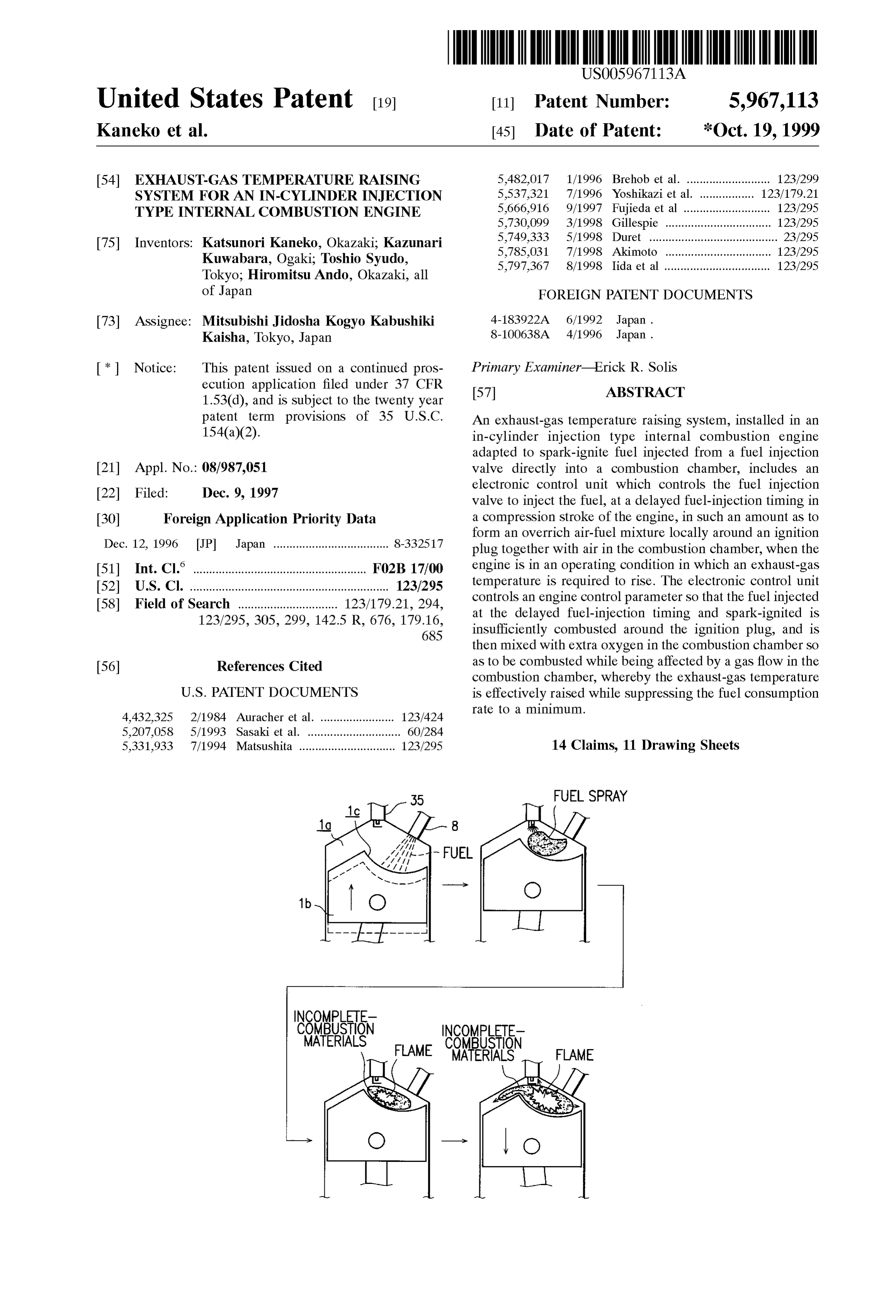
FUEL SPRAY
Page 2
Drawing sheet — no readable text.
Page 3
Drawing sheet — no readable text.
Page 4
FIG. 3
READ SENSOR OUTPUTS S10
INCLUDING CATALYST
TEMPERATURE AND
WATER TEMPERATURE
Yes
PREDETERMINEDTIME
ELAPSED WITH THROTTLEV No
OPENING KEPT
CATALYST ACTIVATED?
TEMPERATURE RAISING
START TIMERTM
Page 5
Drawing sheet — no readable text.
Page 6
Drawing sheet — no readable text.
Page 7
Drawing sheet — no readable text.
Page 8
FIG. 7
TEMPERATURE RASING
CONTROL
SET RETARDED FUEL
NJECTION TIMING
FOR MAININJECTION
SET MAIN
IGNITION TIMING
SET TIMING AND
AMOUNT FOR
PRECEDENT INJECTION
SET RETARDED
IGNITION TIMING
PRECEDENT INJECTION
MANNECTION
IGNITION
END
Page 9
Drawing sheet — no readable text.
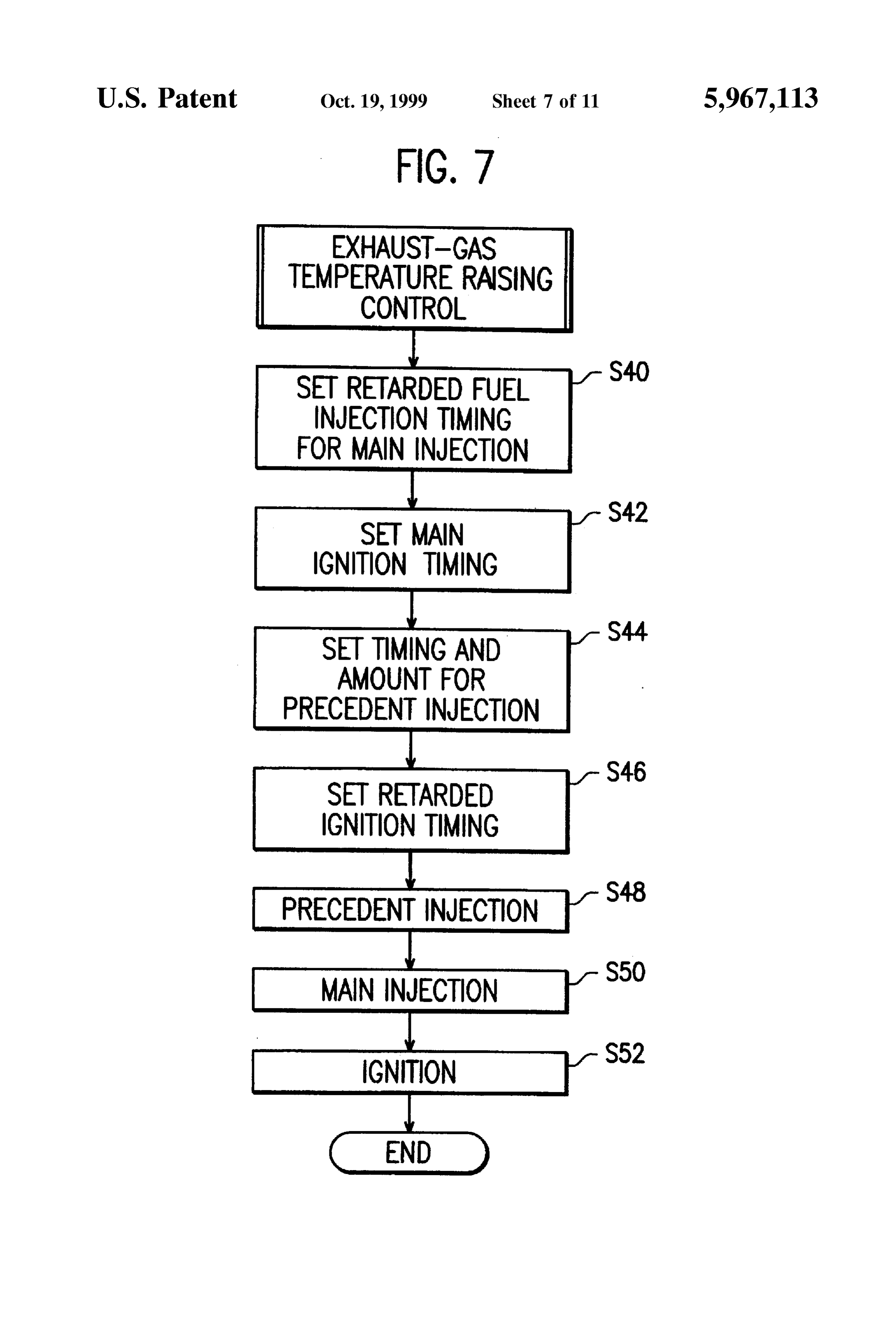
Page 10
Drawing sheet — no readable text.
Page 11
Drawing sheet — no readable text.
Page 12
Drawing sheet — no readable text.
Page 13
EXHAUST-GASTEMPERATURE RAISING burnt without causing any misfire due to the presence of an SYSTEM FOR AN IN-CYLINDER INJECTION overrich mixture around the Spark plug, whereby the engine TYPE INTERNAL COMBUSTION ENGINE output required at the time of acceleration or during high Speed running of a vehicle can be ensured.
BACKGROUND OF THE INVENTION At the time of cold Start of engine, or during a low-load 1. Technical Field of the Invention engine operation at a low ambient air temperature, an The present invention relates to an in-cylinder injection in-cylinder injection type internal combustion engine may type internal combustion engine adapted to inject fuel purification time take much to activate a catalyst of an exhaust-gas device disposed in the exhaust passage of the directly into a combustion chamber and to cause the injected engine. When the engine is operated in the compression-lean fuel to be Spark-ignited for Stratified combustion, and more mode where a large amount of intake air is Supplied into a particularly, to a System for raising the exhaust-gas tempera cylinder, the flow rate of exhaust gas is high, and hence the ture to thereby enable immediate activation of an exhaust exhaust-gas temperature tends to become low. Accordingly, gas purification device of an in-cylinder injection type 15 the catalyst may fail to maintain its activated temperature, internal combustion engine when the engine continuously when the engine is operated in the compression-lean mode effects a lean combustion operation. even if the catalyst has once reached the activation tempera 2. Description of the Related Art ture. To eliminate these problems, various methods are For Spark-ignition type automotive internal combustion proposed for raising the exhaust-gas temperature to effect a engines, various in-cylinder injection type gasoline engines rapid activation of catalyst.
have been proposed. These types of engines inject fuel For example, an in-cylinder injection type internal com directly into a combustion chamber, unlike conventional injectionengine bustion valve proposed in JP-A-4-183922 operates a fuel during compression Stroke of the engine to intake-manifold injection type engines, in which fuel is inject a main injected into an intake manifold and transferred to a com 25 a Spark plug to ignite fuel into a combustion chamber, and actuates bustion chamber. An in-cylinder injection type engine is Valve is operated againtheduring main fuel. Then, the fuel injection typically arranged to inject fuel from a fuel injection valve early Stage of exhaust Stroke expansion Stroke or during an into a cavity formed in the top of a piston of the engine, to kept closed, to thereby inject an additionalintake in which the valve is fuel into the locally generate an air-fuel mixture having an air-fuel ratio combustion chamber, and the Spark plug is actuated again to close to the Stoichiometric air-fuel ratio around an ignition ignite the additional fuel. However, the proposed System plug at ignition timing. This enables a proper combustion of requires a complicated ignition-control logic and cannot a lean air-fuel mixture, whose average air-fuel ratio produce Sufficient energy for the Second ignition. observed in the entirety of the combustion chamber is lean, In this regard, JP-A-8-100638 proposes a method for reduce the emission of harmful exhaust-gas components, 35 permitting an additional fuel to be burnt without utilizing and improve fuel consumption. However, if the engine Spark ignition. In the proposed method, a main fuel is performs Such a lean-combustion operation through the injected during compression Stroke of an engine, a Spark entire operating region, a deficient engine Output may occur plug is actuated to ignite the main fuel, and an additional fuel in Some operating condition. To obviate this, the in-cylinder is injected during expansion Stroke. A flame produced by the injection type engine is arranged to Switch the injection 40 inflammation of the main fuel initiated upon Spark-operation mode between a compression-stroke injection mode and an of the Spark plug propagates to the additional fuel and causes intake-Stroke injection mode depending upon engine oper the same to be burnt. By this method, the additional fuel can ating conditions. be burnt without the need of re-actuating the Spark plug, and When the engine is in a low-load operating region, the 45 the combustion of the additional fuel raises the exhaust-gas temperature, to thereby shorten a time required for activation compression-stroke injection mode is Selected, in which fuel of the catalyst.
is injected mainly during compression Stroke. In this mode, most of the fuel, injected toward the cavity of the piston However, according to the proposed method, the addi during compression Stroke, Stays in the cavity because of the tional fuel must be injected during that time period in which action of a tumble flow of intake air Sucked into the 50 the additional fuel can be enflamed by the flame which combustion chamber during intake Stroke. Therefore, even if propagates proposed during the main combustion. Actually, in the method, the injection timing of the additional fuel
Such a Small amount of fuel, as to make the average air-fuel ratio large, is injected (compression-lean mode), an air-fuel is set to a value ranging from, e.g., 10 to 80 ATDC in terms of crank angle. However, mixture having an air-fuel ratio close to the Stoichiometric 55 during an early Stage of expansion if the additional fuel is injected air-fuel ratio is formed in the cavity around a Spark plug, at Stroke like this, part of the ignition timing, at which the piston approaches the Spark thermal energy produced at the time of combustion of the additional fuel is wasted for the plug. Hence, the, inflammation of the air-fuel mixture by a an intended rise of the exhaust-gas temperaturework of expansion, So that Spark may become possible. This permits a large amount of may not be intake air to be Supplied into the cylinder in the 60 Sufficiently achieved. Furthermore, an amount of additional compression-stroke injection mode, So that pumping loSS is fuel must be increased in order to Sufficiently raise the decreased and fuel consumption is greatly improved. exhaust-gas temperature, causing the fuel consumption to be further worsened.
When the engine is in a medium- or high-load operating region, fuel is injected mainly during intake Stroke, So as to 65 SUMMARY OF THE INVENTION form a mixture with a uniform air-fuel ratio in the combus An object of the present invention is to provide an tion chamber. In this case, a large amount of fuel can be exhaust-gas temperature raising System for an in-cylinder
Page 14
injection type internal combustion engine, which System is in that it does not require additional devices Such as air pump capable of efficiently raising the exhaust-gas temperature and is hence low-priced.
while Suppressing the fuel consumption to a minimum. In the present invention, preferably, said engine control According to the present invention, there is provided an means causes fuel injection timing, Serving as the engine exhaust-gas temperature raising System for an in-cylinder control parameter in the compression Stroke, to be delayed injection type internal combustion engine in which fuel than that in the compression Stroke at the time of an engine injected from a fuel injection valve directly into a combus operation in which the exhaust-gas temperature is not tion chamber is spark-ignited for Stratified combustion. The required to rise, when the control of the fuel injection valve exhaust-gas temperature raising System comprises: fuel is carried out by Said fuel injection control means. injection control means for controlling the fuel injection With this preferred arrangement where the fuel injection Valve to inject the fuel, at a delayed fuel-injection timing in a compression Stroke of the engine, in Such an amount as to time ofis the timing delayed than that in the compression Stroke at the form an overrich air-fuel mixture locally around an ignition temperature isengine not operation in which the exhaust-gas required to rise, the fuel is not completely plug together with air in the combustion chamber, when the combusted around the ignition
plug because of insufficient engine is in an operating condition in which an exhaust-gas fuel atomization caused by the delayed fuel-injection timing, temperature is required to rise; and engine control means for in addition to a local shortage of air required for complete controlling an engine control parameter So that the fuel injectedat in the compression Stake at the delayed fuel fuel combustion. Thus, the ex-haust-gas temperature can be injection timing and Spark-ignited is insufficiently com raised more effectively.
busted around the ignition plug, and is then mixed with extra In the present invention, preferably, the engine control oxygen in the combustion chamber to be combusted while means causes the ignition timing, Serving as the engine being affected by a gas flow in the combustion chamber, control parameter, to be delayed than that at the time of an when a control of the fuel injection valve is carried out by 25 engine operation in which the exhaust-gas temperature is not the fuel injection control means. required to raise, when the fuel injection timing is caused to According to the present invention, when the engine is in be delayed than that in the compression Stroke at the time of an operating condition in which the exhaust-gas temperature the engine operation in which the exhaust-gas temperature is is required to rise, Such an amount of fuel as to form an not required to raise.
overrich air-fuel mixture locally around an ignition plug With this preferred arrangement, the exhaust-gas tem together with air in the combustion chamber is injected in a perature can be raised more effectively. compression stroke. Together with the air in the cylinder, the Preferably, the fuel injection control means controls the injected fuel produces an overrich air-fuel mixture around fuel injection Valve So that part of the fuel is precedently the ignition plug. The overrich mixture is ignited at ignition 35 injected, prior to the injection of fuel effected at the delayed timing in the vicinity of top dead center in the compression fuel-injection timing in the compression Stroke, at timing stroke. The fuel is not completely combusted around the which varies in a range from an early Stage of an intake ignition plug because of a local shortage of air required for Stroke to an early Stage of the compression Stroke. These complete fuel combustion. Thus, part of the injected fuel is 40 intake and compression Strokes belong to the same operating incompletely combusted and produces incomplete cycle of the engine.
combustion materials. Such as hydrocarbon and carbon mon With this preferred arrangement, part of the fuel to be oxide. When the expansion Stroke is entered, a piston moves injected is precedently Supplied into the combustion cham downward and the incomplete-combustion materials are ber to form an extremely lean air-fuel mixture uniformly caused to diffuse in the combustion chamber. At this time, 45 therein, and a main fuel, i.e., most of the fuel to be injected, the incomplete-combustion materials are exposed to a high is injected in the compression Stroke and Spark-ignited to be temperature atmosphere and acquire considerably large acti enflamed. A flame produced in the course of combustion of Vation energy. Thus, the incomplete-combustion materials the main fuel does not propagate to the extremely lean are permitted to adequately react with Oxygen present in the mixture formed by the fuel precedently Supplied, So that the combustion chamber at locations remote from the ignition 50 extremely lean mixture is kept unburnt. Then, the extremely plug, So that they are re-combusted. The re-combustion lean mixture is compressed by the piston which moves takes place moderately, and hence the energy produced by upward and is exposed to heat generated in the course of the re-combustion is utilized for a rise in exhaust-gas combustion of the main fuel, So that a So-called cool frame temperature, without being wasted for expansion work in the 55 reaction takes place in the extremely lean mixture and engine, whereby a catalyst of an exhaust-gas purification produces reactive chemical species (cool-flame-reaction device is immediately heated to be rapidly activated. products), Such as peroxide, hydroxide, and formaldehyde. The exhaust-gas temperature raising System of the present On an occasion that incomplete-combustion materials dif invention is similar in function and effect to a Secondary air 60 fuse in the combustion chamber during the expansion Stroke System for raising the exhaust-gas temperature. The Second and react with extra oxygen present apart from the ignition ary air System Supplies Secondary air from an air pump into plug. So as to be re-combusted, the cool-flame-reaction an exhaust passage in which unburnt materials. Such as products Serve as inflammation inducers to further promote hydrocarbon, carbon monoxide are present, to thereby cause the re-combustion of the incomplete-combustion materials. the unburnt materials to be re-combusted at an ambient 65 AS a result, the exhaust-gas temperature is risen, whereby temperature of approximately 450° C. As compared to the rapid activation of the catalyst of the exhaust-gas purifica Secondary air System, the present invention is advantageous tion device is achieved.
Page 15
S 6
Preferably, an amount of fuel to be precedently injected is embodiment is made, as a function of ratio of an amount of set to a value varying from 10% to 40% of a total amount of fuel, precedently injected in intake Stroke, to a total fuel fuel to be injected per operating cycle per cylinder of the injection amount;
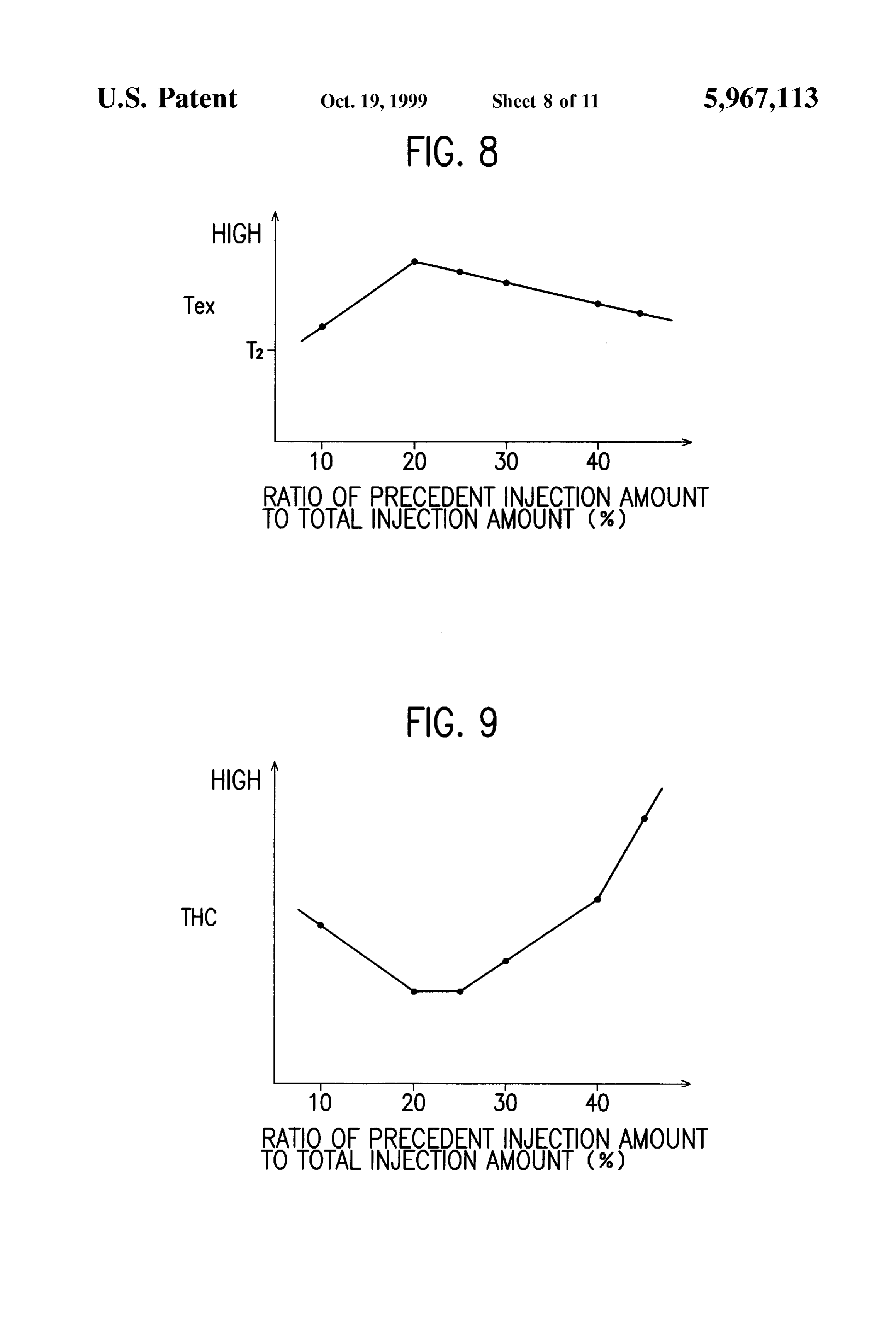
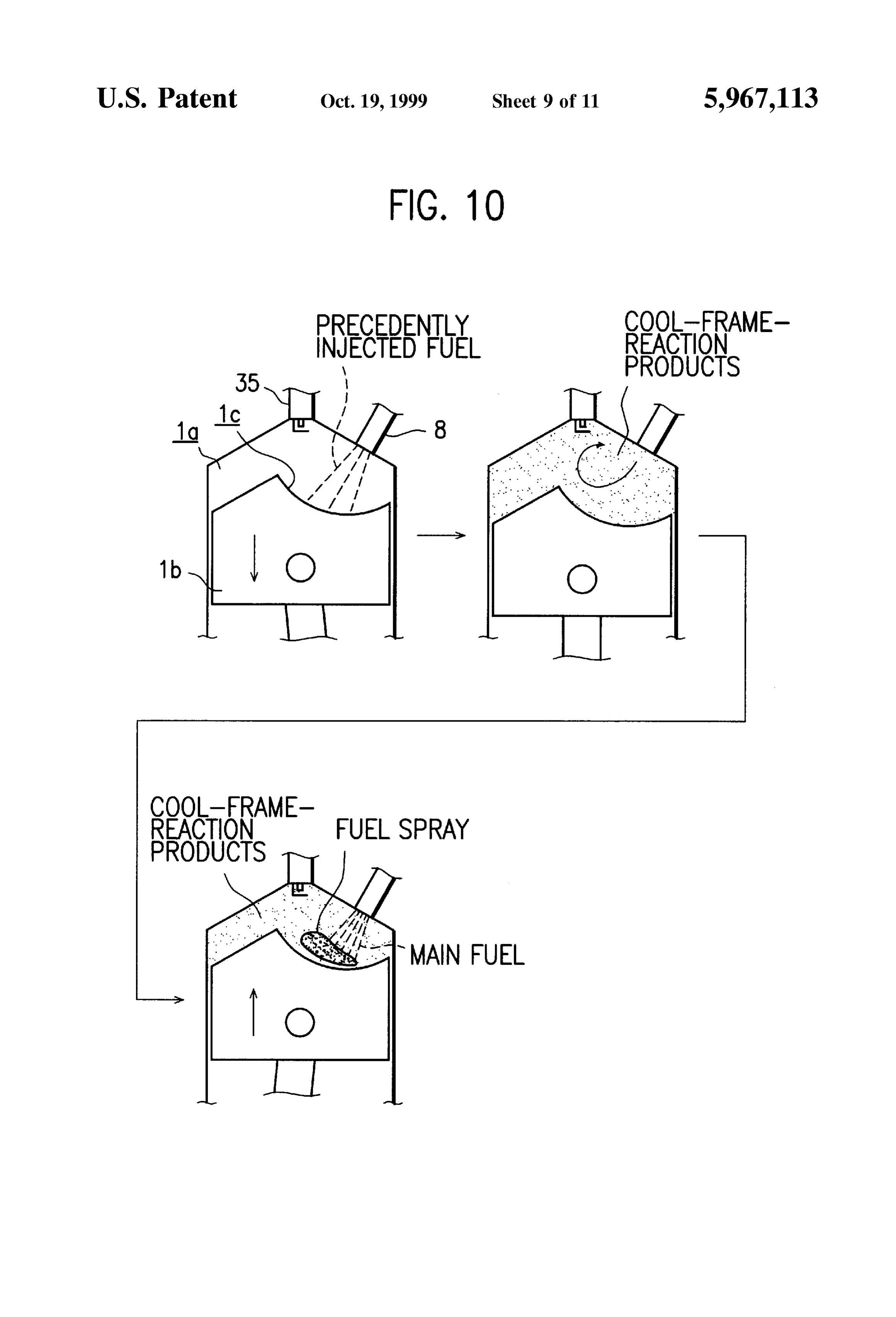
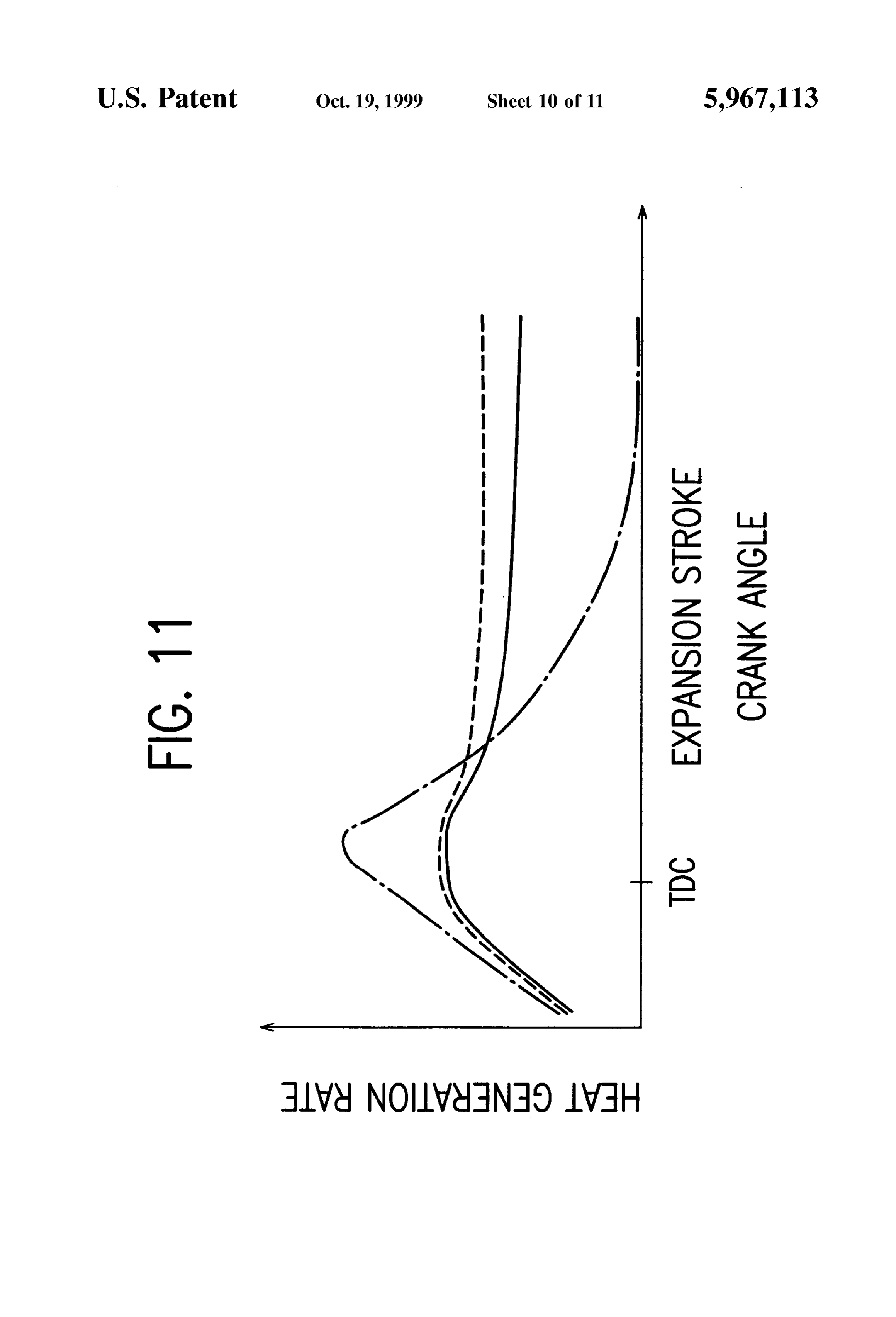
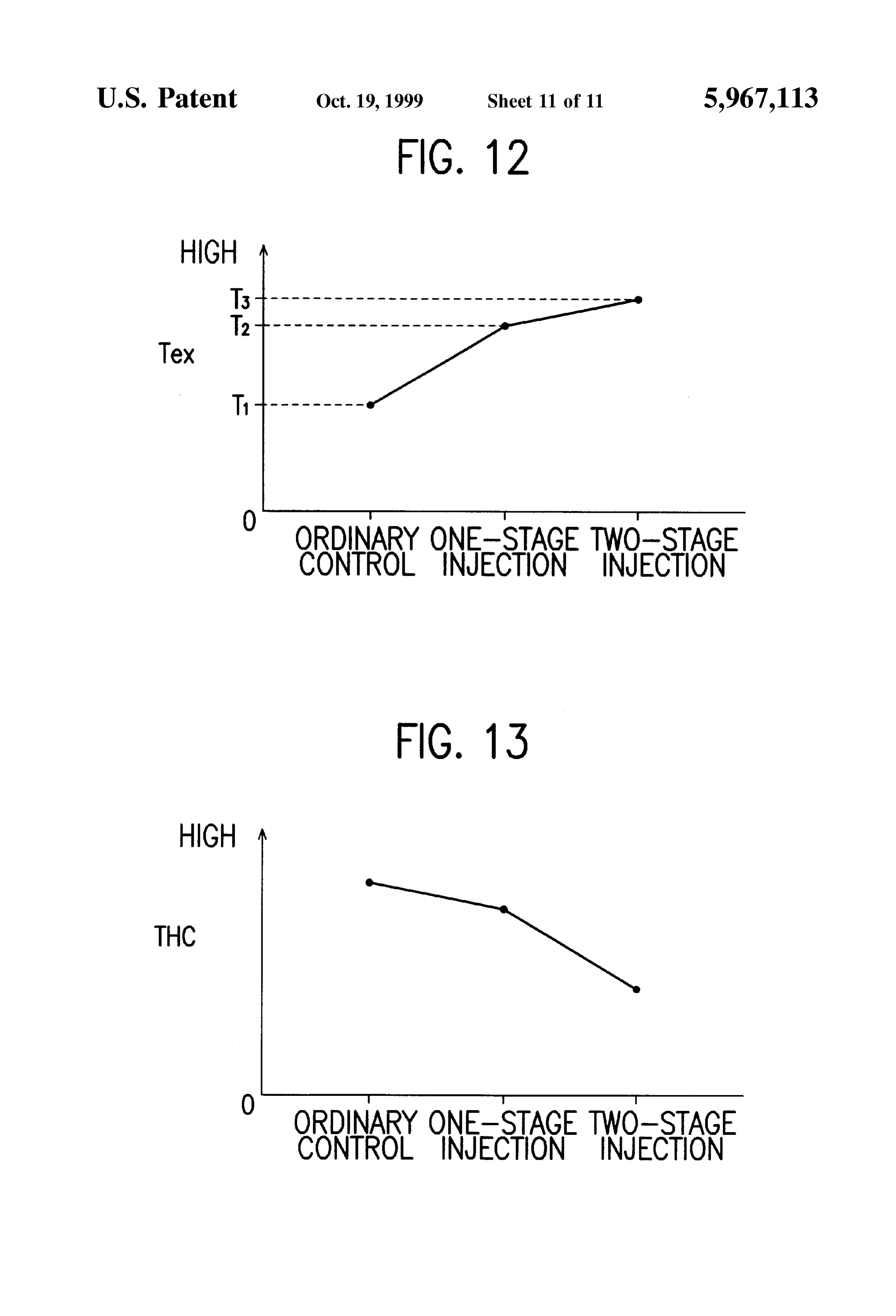
engine. FIG. 10 is a view showing the sequence from a precedent With this preferred arrangement, 10-40% of the total fuel injection process to a main fuel injection process, amount of fuel to be injected per operating cycle per cylinder observed when the precedent fuel injection of the Second is injected precedently, to make it possible to produce Such embodiment is carried out in the intake Stroke; an amount of cool-flame-reaction products as to properly FIG. 11 is a graph showing, as a function of crank angle, Serve as inflammation inducers, which promote the the heat generation rate mainly in expansion Stroke observed re-combustion of incomplete-combustion materials, thereby when the exhaust-gas raising control of the Second embodi adequately raising the exhaust-gas temperature, while pre ment is carried out, venting the generation of Such an excessively large amount FIG. 12 is a graph showing the exhaust-gas temperatures of cool-flame-reaction products as to permit energy gener 15 Tex respectively observed at the time of ordinary fuel ated by re-combustion of incomplete-combustion materials injection control, one-stage fuel injection of the first to be wasted for expansion work in the engine. embodiment, and two-stage fuel injection of the Second Preferably, the exhaust-gas temperature raising System embodiment; and further comprises air amount adjusting means for adjusting FIG. 13 is a graph showing discharge amounts of unburnt an amount of air introduced into the combustion chamber. hydrocarbon THC respectively observed at the time of the The fuel injection control means controls the fuel injection ordinary fuel-injection control, one-stage fuel injection and Valve to increase an amount of the injected fuel with increase two-stage fuel injection.
in the amount of the introduced air adjusted by the air amount adjusting means. 25
DETAILED DESCRIPTION
With this arrangement, the amount of air introduced into With reference to the accompanied drawings, an exhaust the combustion chamber increases, and the amount of fuel gas temperature raising System according to a first preferred injected in the compression Stroke increases with the embodiment of the present invention and an in-cylinder increase in the introduced air amount, whereby the effect of injection type gasoline engine equipped with this System raising the exhaust-gas temperature is further enhanced. will be explained in detail.
BRIEF DESCRIPTION OF THE DRAWINGS In FIG. 1, reference numeral 1 denotes a Spark ignition, in-cylinder injection type in-line four-cylinder automotive
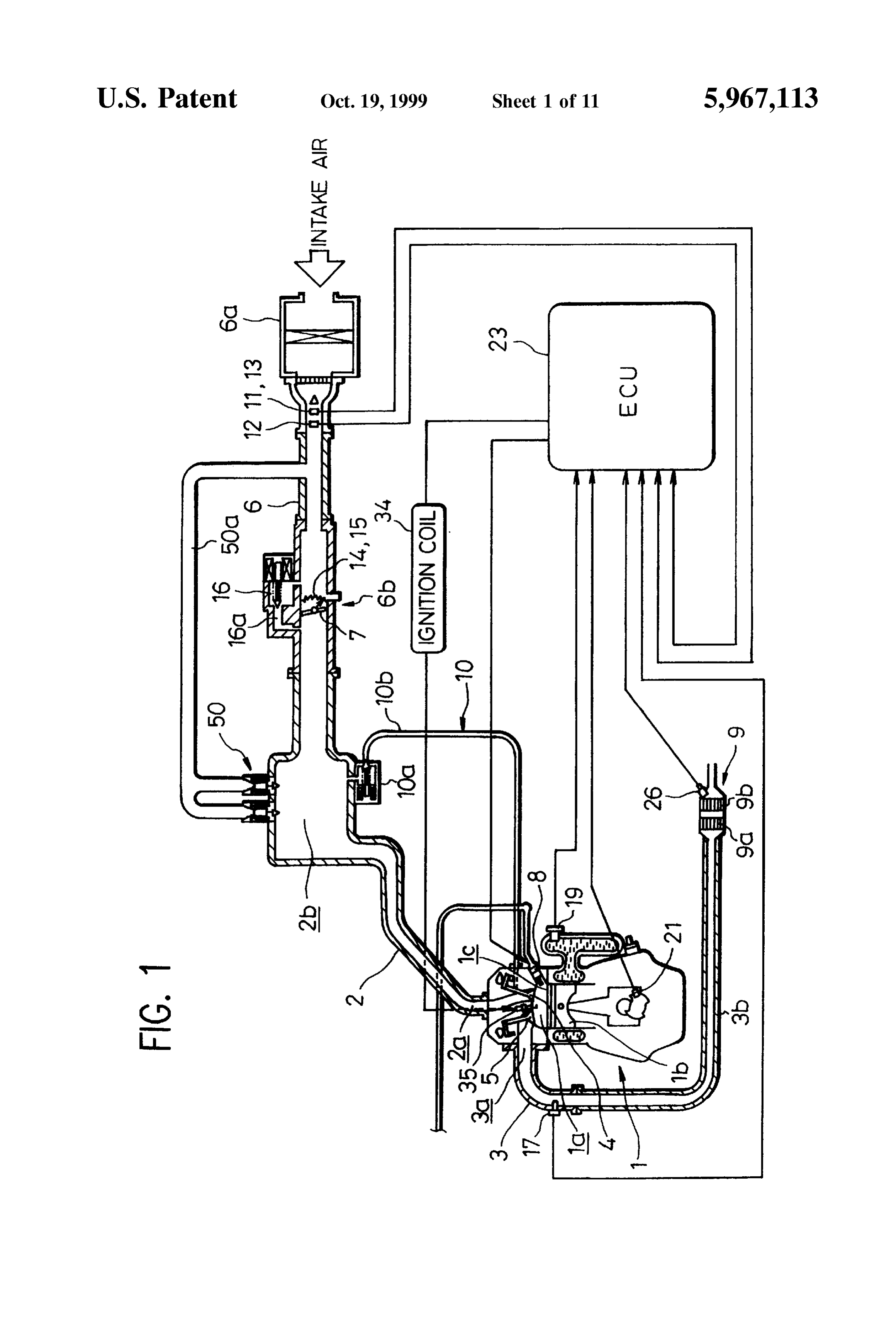
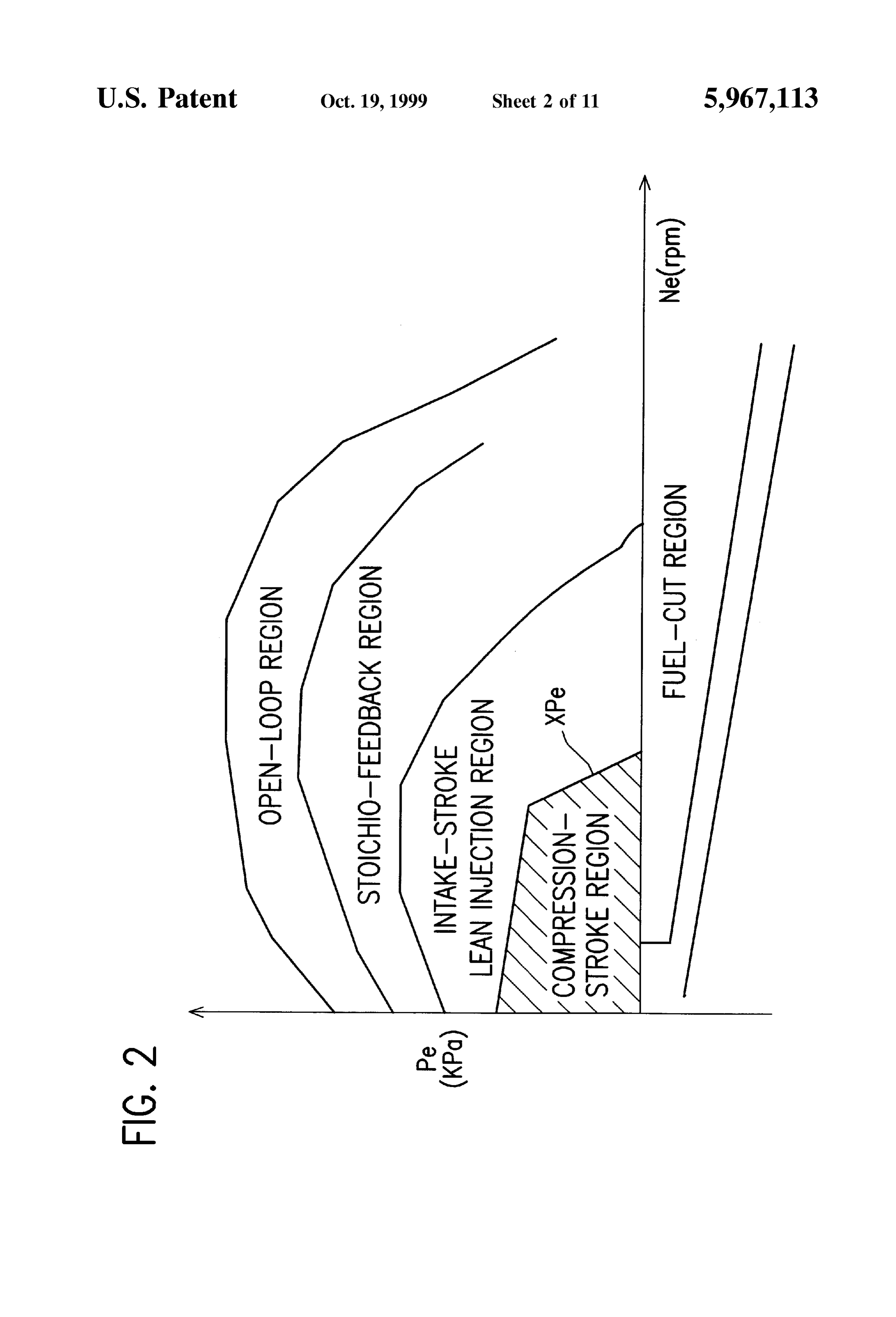
FIG. 1 is a schematic view of an engine provided with an gasoline engine (hereafter referred to simply as an exhaust-gas temperature raising System according to a first 35 “engine'). The engine 1 is a four-cycle engine and has an embodiment of the present invention; operating cycle which consists of intake, compression, FIG. 2 is a view showing a map on which a fuel-injection expansion and exhaust Strokes. The engine has combustion control region at the time of ordinary engine operation is chambers 1a, intake System, an exhaust gas recirculation determined; 40
(EGR) system 10 and the like designed exclusively for
FIG. 3 is a flowchart showing a main routine for exhaust in-cylinder injection.
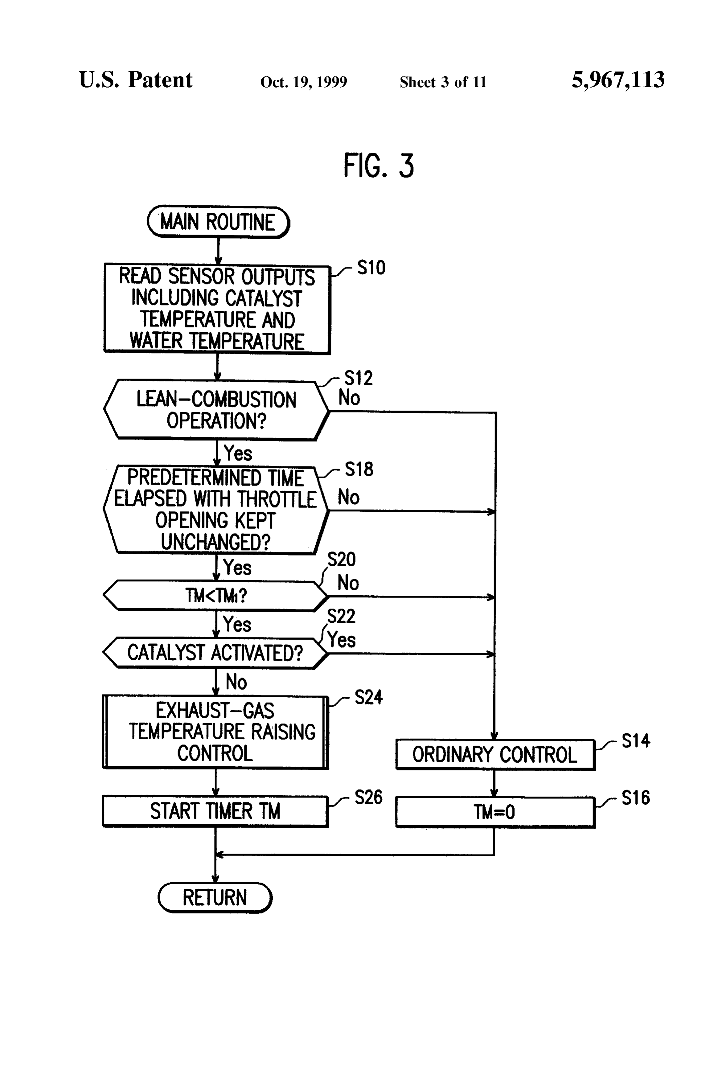
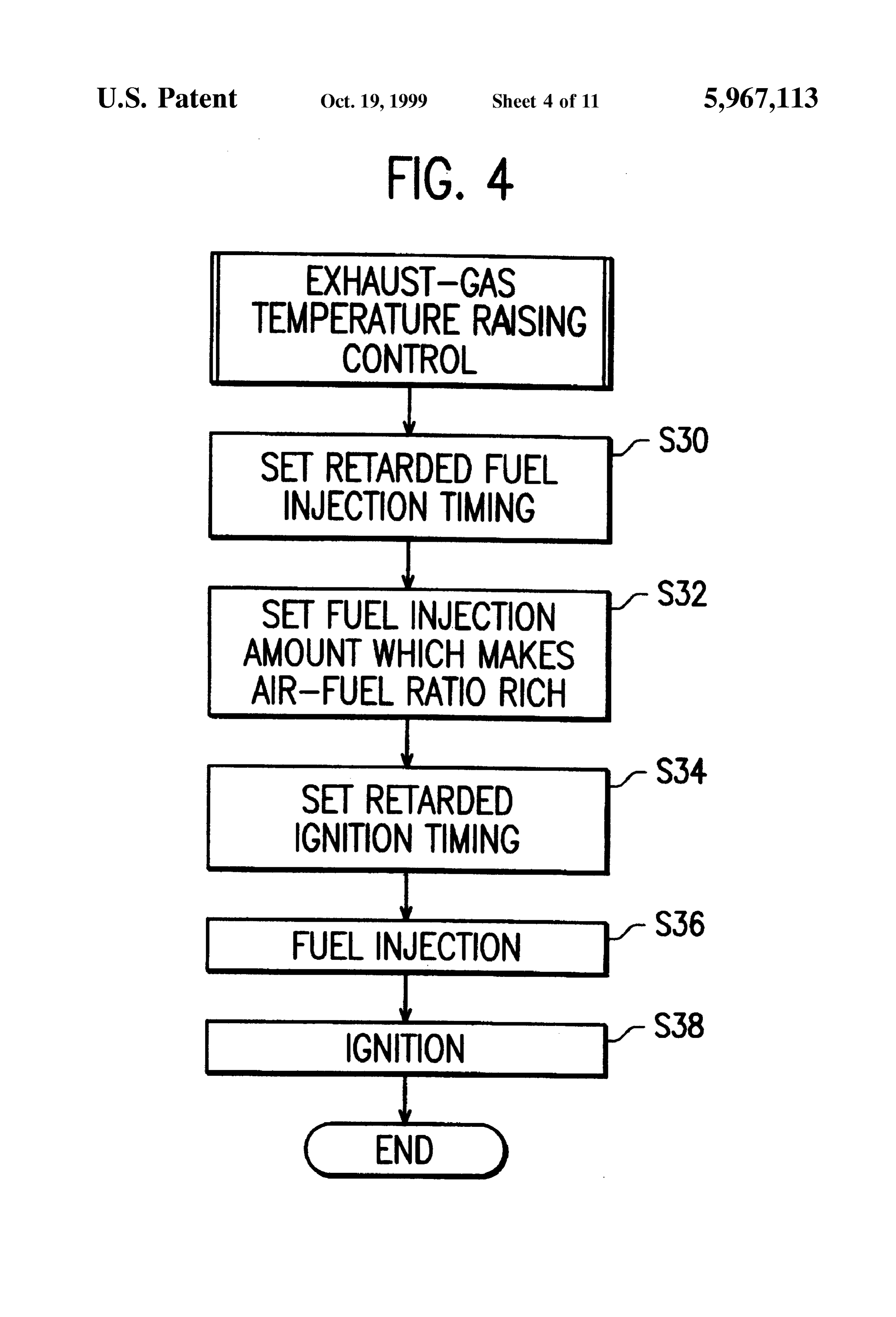
gas temperature raising control eXecuted by the exhaust-gas A cylinder head of the engine 1 is fitted with an electro temperature raising System shown in FIG. 1; magnetic fuel injection Valve 8 and a Spark plug 35 for each FIG. 4 is a flowchart showing, in detail, the exhaust-gas cylinder, So that fuel may be injected from the fuel injection 45 valve 8 directly into the corresponding chamber 1a. A temperature raising control routine shown in FIG. 3;
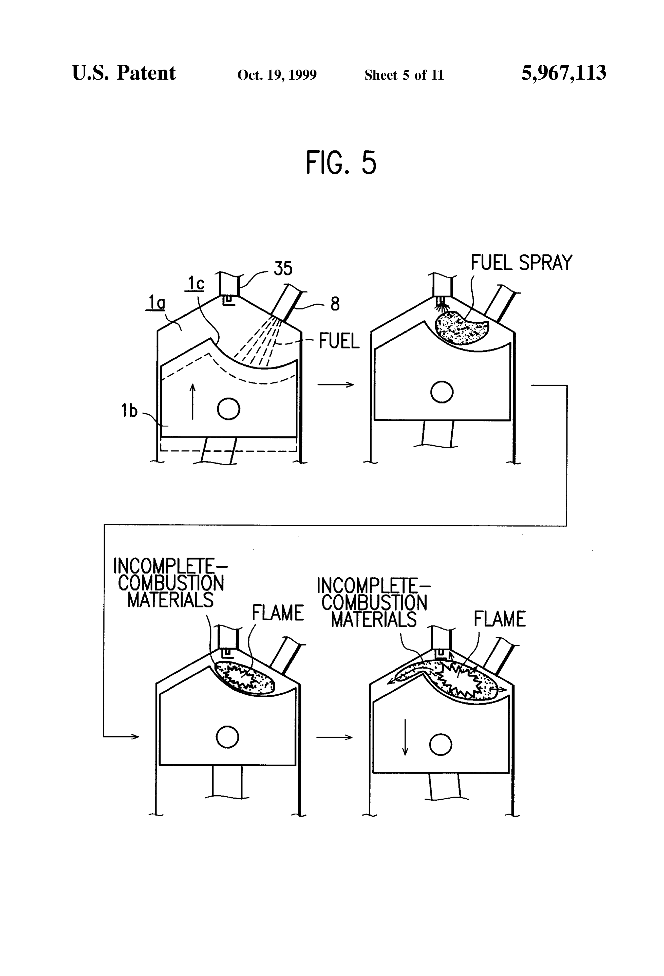
FIG. 5 is a view showing the sequence from a fuel hemispherical cavity (FIGS. 10 and 11) is formed in the top Surface of a piston disposed in the cylinder for reciprocal injection process to a combustion process, observed when motion therein. The cavity is located at a position to which the exhaust-gas temperature raising control of the first fuel Spray can reach if the fuel is injected from the fuel embodiment is carried out; 50 injection valve 8 at the timing at which the piston reaches a
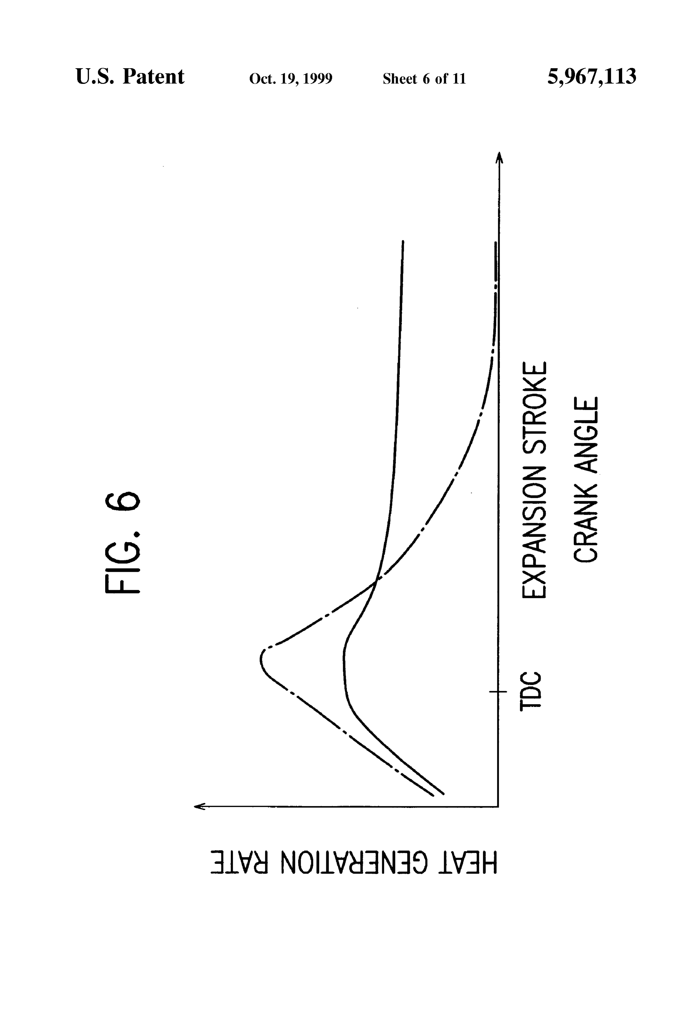
FIG. 6 is a graph showing, as a function of crank angle, reciprocal moving position thereof close to the top dead a heat generation rate mainly in expansion Stroke observed center in a compression Stroke. The theoretical compression when the exhaust-gas temperature raising control of the first ratio of the engine 1 is set to a value (in this embodiment, embodiment is carried out; 55 approximately 12) higher than that of an intake-manifold FIG. 7 is a flowchart showing an exhaust-gas temperature injection type engine. A DOHC four-valve system is raising control routine according to a Second embodiment of employed as a valve driving mechanism. An intake-side the present invention; camshaft and an exhaust-Side camshaft for respectively FIG. 8 is a graph showing exhaust-gas temperature TeX, driving an intake valve 9 and an exhaust valve 10 are observed when the exhaust-gas temperature raising control 60 rotatably held at an upper portion of the cylinder head 2. is carried out, as a function of ratio of an amount of fuel, The cylinder head 2 is formed with intake ports 2a, each precedently injected in intake Stroke, to a total fuel injection of which extends Substantially upright between the cam amount, shafts. Intake air flow having passed through the intake port FIG. 9 is a graph showing an amount of unburnt hydro 65 2a can generate a reverse tumble flow in the combustion carbon discharged from an exhaust port, observed when the chamber 1a. Exhaust ports 3a extend substantially in the exhaust-gas temperature raising control of the Second horizontal direction, as in the case of those of ordinary
Page 16
engines. A large-diameter EGR port, not shown, diverges and NOx are purified, and is then muffled by the muffler, to obliquely from the exhaust port concerned. be discharged to the atmospheric air. In FIG. 1, reference numeral 19 denotes a water tempera The catalyst 9, which is a combination of a lean NOx ture Sensor for detecting a cooling water temperature Tw; 21, catalyst 9a and a three way catalyst 9b, is suitable for the
a crank angle Sensor for outputting a crank angle Signal SGT engine 1 arranged to perform fuel-economy operation while at predetermined crank positions (in this embodiment, 5 controlling the air-fuel ratio to the fuel-lean side (lean side). BTDC and 75 BTDC) for each cylinder; and 34, an ignition The three way catalyst 9b purifies CO, HC, and NOx in coil for Supplying a high Voltage to the Spark plug. 35. One exhaust gas when the engine operates at the Stoichiometric of the camshafts, which rotate at half the speed of the air-fuel ratio. The lean NOx catalyst 9a purifies NOx in crankshaft, is fitted with a cylinder discriminating Sensor exhaust gas which cannot Sufficiently be purified by the three (not shown) for outputting a cylinder discriminating signal way catalyst 9b, when the engine operates with a lean SGC, whereby the cylinder, for which the crank angle Signal
SGT is output, is discriminated based on the Sensor Signal the downstream mixture. The three way catalyst 9b is positioned on SGC, 15 side of the lean NOx catalyst 9a, and consequently, the purification of NOx in the lean NOx
The intake ports 2a are connected, through an intake catalyst 9a is not interrupted by the three way catalyst 9b, manifold 2, including a Surge tank 2b, with an intake pipe 6 and CO and HC which cannot sufficiently be purified in the which is provided with an air cleaner 6a, a throttle body 6b, lean NOx catalyst 9a can Surely be purified in the three way and a stepper-motor type idle Speed control valve catalyst 9b. By the way, if the lean NOx catalyst has a three (hereinafter referred to as idle control valve) 16. The intake way function, it is possible to provide the lean NOx catalyst pipe 6 is further provided with a large-diameter air bypass only.
pipe 50a, through which intake air is introduced, bypassing the throttle body 6b, to the intake manifold 2, and in which body. A fuel tank, not shown, is disposed at the rear of avehicle a large linear-Solenoid type air bypass valve (ABV valve (air 25 ValvesFuel 8 is supplied from the fuel tank to the fuel injection through a fuel Supply System, not shown. Namely, amount adjusting means)) 50 is disposed. The air bypass fuel Stored pipe 50a has a flow area substantially equal to that of the motor-operated lower in the fuel tank is Sucked up by an electric intake pipe 6, So that a quantity of intake air, required for low the engine 1 through preSSure
fuel pump, and Supplied to low-pressure feed pipe. The fuel or medium speed region of the engine 1, can flow through the pipe 50a when the ABV valve 50 is fully open. The idle Valve 8 through a high-pressure feed pipe each Supplied toward the engine 1 is fed to fuel injection and a delivery pipe control valve 16 has a flow area Smaller than that of the ABV valve 50 and is used to finely adjust the intake air amount. by a high-pressure fuel pump which is attached to the cylinder head.
The throttle body 6b is provided with a butterfly type throttle valve 7 for opening and closing the intake passage 35 An ECU (electronic control unit) 23 is provided in a formed therein, a throttle position Sensor 14 for detecting the passenger cabin of the vehicle and includes an I/O unit, throttle opening degree 0th as accelerator opening degree, storage units (ROM, RAM, BURAM, etc.) used to store and an idle Switch 15 for detecting a fully-closed state of the control program, control map and the like, central proceSS throttle valve. An intake air temperature Sensor 12 and an 40 ing unit (CPU), timer counter, and the like. The ECU 23 atmospheric pressure Sensor 13 for determining the density conducts an overall control of the engine 1. of intake air are disposed in the air cleaner 6a. These Sensors Various Switches for detecting the operating States of an deliver output signals indicating the atmospheric preSSure Pa air conditioner, power Steering device, automatic transmis and the intake air temperature Ta, respectively. In the Sion and the like, which apply loads to the engine 1 when vicinity of the inlet of the intake pipe 6, a Karman's Vortex 45 operated, are respectively connected to the input Side of the type air flow sensor 11 is disposed. The an flow sensor ECU 23 which receives respective detection signals from outputs a vortex occurrence signal which is proportional to these Switches. In addition to the above-mentioned various the Volumetric air flow rate Qa per intake Stroke. Sensors and Switches, many Switches and Sensors (not The aforementioned EGR ports are each connected to the 50 shown) are connected to the input side of the ECU 23, the downstream of the throttle valve 7 and the upstream of the output Side of which is connected to warning lights, pieces intake manifold 2 through a large-diameter EGR pipe 10b in of equipment and the like.
which a stepper-motor type EGR valve 10a is provided. In accordance with input signals Supplied from the Sen The exhaust ports 3a are connected to an exhaust mani Sors and Switches concerned, the ECU 23 determines fuel fold 3 provided with an O sensor 17. An exhaust pipe 55 injection mode, fuel injection amount, fuel-injection termi (exhaust passage) 3b which is provided with a catalyst nation timing, ignition timing, EGR gas introduction amount converter 9 for exhaust-gas purification, a muffler (not and the like, and then controls the fuel injection valves 8, the shown) and the like is connected to the exhaust manifold 3. ignition coil 34, the EGR valve 10a and the like. The O. Sensor 17 detects the oxygen concentration in 60 Next, an ordinary control of the engine 1 effected in a case exhaust gas, and outputs a detection signal. Attached on the where an exhaust-gas temperature raising control, described downstream Side of the catalyst 9 is a catalyst temperature later, is not performed will be explained briefly. Sensor 26 for detecting the temperature Tcc of the catalyst or At the start of the engine, which is in a cold state, the ECU its vicinity (hereinafter referred to as catalyst temperature). 23 Selects the intake-stroke injection mode, and controls fuel The exhaust gas discharged from the combustion chamber 65 injection to attain a relatively rich air-fuel ratio. The reason 1ato the exhaust manifold 3 enters the catalyst converter 9 for doing this is that Since the rate of vaporization of fuel is in which three harmful exhaust gas components CO, HC, low when the engine is in a cold State, a misfire and emission
Page 17
of unburnt fuel components are unavoidable if the fuel example, approximately 50), the injected fuel is permitted to injection is performed in the compression-stroke injection be enflamed. Because of the engine operation at Such a lean mode. Furthermore, the ECU 23 closes the ABV valve 50 air-fuel ratio, the emission of CO and HC becomes very during the engine Start-up. In this case, intake air is Supplied Small, and the emission of NOX can also be restrained to a into the combustion chamber 1a through clearances between 5 low level by exhaust-gas recirculation. Moreover, by open the throttle valve 7 and the peripheral wall of the intake pipe ing the ABV valve 50 and the EGR valve 10a to supply large 6 and through the bypass passage where the idle control amounts of air and exhaust gas, the pumping loSS is reduced. valve 16 is disposed. By the way, the idle control valve 16 Because of the engine operation with the lean air-fuel ratio and the ABV valve 50 are unitarily controlled by the ECU in cooperation with the reduction of pumping loSS, the fuel 23, and their valve opening degrees are determined accord consumption is largely improved. An idle Speed control ing to an introduction quantity of intake air (bypass air) to responsive to the increase and decrease of engine load is be Supplied, bypassing the throttle valve 7, to the engine. performed by increasing or decreasing the quantity of fuel After the Start-up of the engine and until the cooling water injection, So that control response is also very high. temperature Tw rises to a specified value, the ECU23 selects 15 When the engine runs at a low or middle Speed, the engine the intake-stroke injection mode for fuel injection, as in the is operated in the intake-Stroke lean region or the Stoichio case of engine start-up, and keeps the ABV valve 50 closed. feedback region (Stoichiometric air-fuel ratio feedback con Furthermore, as in the case of an intake-manifold injection trol region) shown in FIG.2. In that case, the ECU23 selects type engine, idle Speed control is carried out by adjusting the the intake-stroke injection mode.
opening degree of the idle control valve 16 in accordance More specifically, if the engine operating State, repre with the engine load which increases and decreases with a Sented by average effective preSSure Pe and engine Speed change in the operating State of auxiliary machinery Such as Ne, belongs to the intake-stroke lean region, the intake air conditioner. The ABV valve 50 is also opened, if needed. Stroke lean injection mode is Selected, and the opening When the O sensor 17 reaches its activation temperature, 25 degree of the ABV valve 50 and the quantity of fuel injection the ECU 23 starts the air-fuel ratio feedback control accord are So controlled as to attain a relatively lean air-fuel ratio ing to the output voltage of the O. Sensor 17, So that harmful (for example, approximately 20 to 23). In the intake-stroke exhaust gas components may be purified by the catalyst 9. lean injection mode, the intake air entering through the AS explained above, when the engine is in a cold State, the intake port 2a forms an inverse tumble flow in the combus fuel injection control is performed in a manner Similar to that tion chamber, to produce a turbulence effect. Therefore, by for the intake-manifold injection type engine. Control controlling the fuel-injection Start timing and the fuel response and control accuracy are high in the in-cylinder injection termination timing, inflammation of the mixture injection type engine 1 which entails no adhesion of fuel having Such a lean air-fuel ratio is enabled. drops onto inner wall Surfaces of intake ports. 35 When the engine operates in the Stoichio-feedback region Upon completion of warming-up the engine 1, the ECU (S-FB region), the S-FB control mode is selected, and the 23 retrieves a fuel-injection control region at the present EGR valve 10a is controlled to be opened and closed, with time from the fuel-injection control map in FIG. 2 on the the ABV valve 50 kept closed (the control of the EGR valve basis of engine Speed Ne and target effective in-cylinder 40 10a is made only when the engine operates in a Specified pressure (target load) Pe determined by throttle opening 0th range of the S-FB region). In addition, the air-fuel ratio or the like. Then, a fuel injection mode and a fuel injection feedback control is performed according to the output volt quantity, which are Suitable for the present control region, age of the O2 Sensor 17. In the S-FB region, a larger engine are determined, and the fuel injection valve 8 is driven. In output is obtained for the reason that the engine operates at addition, a control of opening degrees of the ABV valve 50 45 a high compression ratio, and harmful exhaust-gas compo and the EGR valve 45 is carried out. nents are purified by the catalyst 9, with the emission of NOx For example, when the engine is in a low-load, low-Speed reduced by exhaust-gas recirculation.
region, e.g., at the time of idle operation, the engine is When the engine is rapidly accelerated or runs at a high operated in the compression-stroke lean injection region 50 Speed, the open-loop control region shown in FIG. 2 is shown by the hatched region in FIG. 2. In this case, the ECU entered. The ECU 23 selects the open-loop control mode 23 Selects the compression-stroke injection mode, controls (intake-stroke injection mode), closes the ABV valve 50, the opening degrees of the ABV valve 50 and the EGR valve and controls fuel injection according to throttle opening 0th, 10a according to the engine operating State, and controls the engine Speed Ne and the like to attain a relatively rich fuel injection to inject Such a quantity of fuel as to make the 55 air-fuel ratio. During this mode, a high engine output can be air-fuel ratio lean (in the present embodiment, approxi obtained for the reasons that the compression ratio is high, mately 20 to 40). The intake air, Sucked through the intake a stream of intake air forms the inverse tumble flow, and port 2a into the combustion chamber before the fuel inertia effect is attained since the intake port 2a eXtends injection, forms an inverse tumble flow. By the action of the 60 approximately upright relative to the combustion chamber inverse tumble flow, fuel spray is retained in the cavity 1c 1a.
formed in the piston. Consequently, at ignition timing, an At the time of coasting engine operation while the engine air-fuel mixture with an air-fuel ratio close to the Stoichio runs at a middle or high Speed, the fuel-cut region shown in metric air-fuel ratio is formed around the Spark plug. 35. FIG. 2 is entered. The ECU 23 completely stops the fuel After completion of warming-up of the engine, the vapor 65 injection, So that the fuel consumption is improved and the ization rate of fuel increases. Accordingly, even if the whole emission of harmful exhaust-gas ingredients is decreased. or average air-fuel ratio is made extremely lean (for The fuel-cut operation is immediately Stopped, if the engine
Page 18
Speed Ne becomes lower than a restoration Speed, or if the If the result of the determination at step S12 is negative driver depresses the accelerator pedal. (No), that is, if the engine is not operated in the lean In the following, the operation of the exhaust-gas tem combustion region or if a Substantial change in throttle perature raising System having the aforementioned construc opening 0th is determined, then it is determined that the tion will be explained. engine is operated with an air-fuel ratio close to the Sto The main routine for exhaust-gas temperature raising ichiometric air-fuel ratio in a premixed-combustion region control shown in FIG. 3 is executed by the ECU 23 each other than the Stratified-combustion region and the premixed time a crank angle Signal SGT is output from the crank angle lean-combustion region. In this manner, if the first require Sensor 21, while the above-mentioned ordinary engine con ment is not satisfied and hence the execution of the exhaust trol is carried out. gas temperature raising control is unnecessary, the flow First, at step S10, the ECU 23 reads various engine advances to step S14 wherein the aforementioned ordinary operating State quantities respectively detected by various control is carried out. More Specifically, normal fuel Sensors. The thus detected quantities include the catalyst 15 injection meet the control and normal ignition-timing control, which present engine operating region, are carried out.
temperature Tcc, engine cooling water temperature TW, intake air flow rate Qa, throttle opening 0th, engine Speed Next, at step S16, a timer TM which measures a time elapsed from the Start
Ne, atmospheric preSSure Pa, and intake air temperature Ta. is reset to a valueof the exhaust-gas temperature raising control
Next, in order to determine whether or not first to fourth conditions for execution of the exhaust-gas temperature If the result of determination at step S12 is affirmative raising control (hereinafter referred to as first to fourth (Yes), that is, if the engine is operated in the lean requirements) are satisfied, steps S12, S18, S20 and S22 are combustion region (compression-stroke lean injection executed in Sequence. region or intake-stroke lean injection region) and if a change At Step 12, a determination is made as to whether or not 25 in in throttle opening 0th is small to indicate that the vehicle is a steady running State, it is determined that the engine is the engine 1 is operating in a lean-combustion State where operated in the lean-combustion region or in the premixed Stratified combustion or premixed lean-combustion is made. lean-combustion region. When the first requirement is Sat More Specifically, whether or not the engine 1 is operated in isfied in this manner, the lean-combustion operating region (the compression determine whether or notthetheflow advances to step S18 to Second requirement is Satisfied.
Stroke lean injection region or the intake-stroke lean injec tion region shown in FIG. 2) is determined based on engine At step S18, a determination is made as to whether or not Speed Ne and target in-cylinder effective pressure Pe, which a time measured by that timer reaches the aforementioned is determined from throttle Valve opening 0th and engine predetermined time period, which is caused to restart when Speed Ne. Also, a determination is made as to whether or not 35 the difference between the throttle opening 0th read at step a change in the throttle valve opening 0th is Small So that a S10 and that read in the preceding control cycle exceeds a vehicle is in a steady running State, by determining whether certain threshold value. In other words, whether or not the or not the difference between the throttle valve opening 0th throttle opening 0th is maintained Substantially at constant read at Step S12 and that read in the preceding control cycle for the predetermined time period is determined at step S18. exceeds a certain threshold value. 40 The reason why the Second requirement requires that the The reason why the first requirement requires that the throttle opening 0th is maintained at constant over the engine is operated in a lean-combustion State and that a predetermined time period is as follows: While the throttle change in throttle valve opening is Small is as follows: opening 0th is maintained at constant under the condition the A lean mixture whose air-fuel ratio ranges from about 20 45 first requirement is Satisfied, the engine operation in the to 40 can generate, when combusted, a Small quantity of lean-combustion State where the catalyst temperature Tcc heat. Thus, when the engine is operated in a lean-combustion tends to decrease is continued. Thus, if a Substantial change State, especially in a Stratified-combustion State, an amount does not occur in the throttle opening 0th for the predeter of heat generated by the combustion becomes Small, So that 50 mined time period, it is understood that the catalyst tem the exhaust-gas temperature TeX becomes low. In Such a perature Tcc is more likely to decrease.
case, the catalyst temperature Tcc of the catalyst converter 9 If the result of determination at step S18 or if the second is likely to be lower than a lower activation temperature limit requirement is not Satisfied, the flow advances to Step S14 T1 (e.g., 400° C). where the ordinary control is carried out. A change in throttle valve opening 0th in the increasing 55 If the result of determination at step S18 is affirmative for direction indicates a request for accelerated engine opera the reason, e.g., that the idle engine operation in the tion. In response to the request for deceleration, the fuel compression-stroke lean injection region continues for the injection amount is increased. Hence, the exhaust-gas tem predetermined time period, it is determined that the Second perature may increase even if no exhaust-gas temperature requirement is Satisfied and hence the flow proceeds to Step raising control is made. When the throttle valve opening 0th 60 S20 in order to make a determination as to whether or not the changes to decrease when the engine runs at a medium or third requirement is Satisfied.
high Speed, fuel cut control is carried out to Stop the fuel At step S20, whether or not a time period, measured by Supply to the engine. In the fuel-cut region, if fuel is Supplied the timer TM and indicative of the time for which the to increase the exhaust-gas temperature, a decelerated 65 exhaust-gas temperature raising control has been conducted, engine operation which meets the driver's intention of is less than a predetermined time period TM1 is determined. deceleration cannot be made. The reason why the third requirement requires that the first
Page 19
and Second requirments comtinue for a time period less than At step S30, the ECU 23 Serving as engine control means the predetermined time period TM1 is as follows: It is Sets the fuel injection timing (engine control parameter) So unnecessary to raise the exhaust-gas temperature for acti as to be retarded as componed to that for the normal control. Vation of the catalyst, if the exhaust-gas temperature raising More Specifically, the fuel injection timing is greatly control has been carried out for a time period equal to or retarded from, e.g., 57 BTDC suitable for the compression longer than the predetermined time period TM1 so that the Stroke lean injection mode in the ordinary control to a value catalyst converter 9 has been ordinarily already activated. ranging from 20° BTDC to TDC. Preferably, the fuel injec If the result of determination at step S20 is negative or if tion timing for the exhaust-gas temperature raising control is the time period measured by the timer TM reaches the set to a value falling within a range from 15 BTDC to 5 predetermined time period TM1, then it is determined that BTDC.
the third requirement is not Satisfied. In this case, the flow At Step S32, the fuel injection amount is Set to Such a proceeds to step S14 where the aforementioned ordinary control is carried out. value as to locally form a rich air-fuel mixture in the cavity On the other hand, if the result of determination at step 15 control, a Specifically, 1c. More rich mixture in the exhaust-gas temperature raising having an air-fuel ratio ranging from
S20 or if the time period measured by the timer TM is less than the predetermined time period TM1, then it is deter 8 to 10 is formed in the cavity 1c, unlike the compression mined that the third requirement is Satisfied, and the flow Stroke lean injection mode for the normal control in which advances to Step S22. an air-fuel mixture having an air-fuel ratio close to the Stoichiometricair-fuelratioisformedinthecavity. Besides, the
At Step S22, a determination is made as to whether or not the catalyst converter 9 is in an activated State, by deter fuel injection amount for the exhaust-gas temperature rais mining whether or not the catalyst temperature Tcc is equal ing control is Set to Such a value as to make the entire or to or higher than the lower activation temperature limit T1 average air-fuel ratio equal to the Stoichiometric air-fuel (e.g., 400° C.). 25 ratio or to a slightly lean air-fuel ratio of 14 to 18, for instance.
If the result of determination at step S22 is affirmative or At Step S34, the ignition timing (engine control if the catalyst temperature Tcc is equal to or higher than the lower activation temperature limit T1 (at the time of unful parameter) is set by the ECU 23 Serving as engine control fillment of the fourth requirement), it is unnecessary to carry means to a value retarded than that for the normal control, out the exhaust-gas temperature raising control for the as in the case of the fuel injection timing. That is, the ignition activation of the catalyst converter. In this case, the flow timing which ranges, e.g., from 20 BTDC to 25 BTDC for proceeds to Step S14 where the ordinary control is carried the compression-stroke lean injection mode in the normal Out. control is greatly retarded to a value ranging from 15 BTDC to 5 ATDC,
On the other hand, if the result of determination at step 35 dependence on preferably ranging from 10 BTDC to TDC, in the fuel injection timing.
S22 is negative or if the first to fourth requirement, i.e., the first to fourth conditions for execution of the exhaust-gas Next, at step S36, fuel injection is carried out based on the temperature raising control are Satisfied, the flow advances thus Set fuel injection timing and fuel injection amount. At to Step S24 where the exhaust-gas temperature raising Step S38, the ignition is made based on the ignition timing control is carried out. 40 Set in the above manner.
In a case where the engine is operating, just before the In the following, with reference to FIG. 5, the function of Start of the exhaust-gas temperature raising control, in the the exhaust-gas temperature raising control will be further compression-stroke lean injection mode to effect the Strati explained.
fied combustion, the fuel injection amount, fuel injection 45 At first, as shown in upper left part of FIG. 5, fuel is timing, ignition timing, etc., are changed to those for the injected from the fuel injection valve 8 in compression exhaust-gas raising control, while preventing a Substantial Stroke in amount larger than the ordinary injection, i.e., in change in engine output torque. In a case where the engine amount Such as to locally form a mixture having a rich is operating in the intake-stroke lean injection mode, just air-fuel ratio ranging, e.g., from 8 to 10. At the fuel injection before the Start of the exhaust-gas temperature raising 50 timing, which is retarded to a value of 20 BTDC to TDC as control, to effect the premixed lean combustion, the fuel mentioned above, the piston 1b is at a upward position than injection amount, fuel injection timing, ignition timing, etc., the ordinary piston position illustrated by broken line. are changed to those for the compression-stroke lean injec Then, as shown at upper right part of FIG. 5, the ignition tion mode, while preventing a Substantial change in engine 55 is made at the timing ranging from 15 BTDC to 5 ATDC. output torque. Ordinarily, the opening degrees of the ABV Ordinarily, the crank angle difference between the fuel 50, etc., are kept unchanged when a shift is made from the injection timing (approximately 57 BTDC) and the ignition ordinary control to the exhaust-gas temperature raising timing (20 BTDC to 25 BTDC) ranges from 32 to 37, so control. Especially, as for the ABV, no opening/closing that most of fuel Spray reaches the ignition plug 35 at the control is made at that time. 60 ignition timing. By contrast, in the case of the exhaust-gas
In the exhaust-gas temperature raising control at Step S24, temperature raising control, the crank angle difference an exhaust-gas temperature raising control routine shown in between the fuel injection timing and the ignition timing, FIG. 4 is executed. Meanwhile, in the exhaust-gas tempera which varies from 15 BTDC to 5 ATDC depending on the ture raising control, the fuel injection is performed in the 65 fuel injection timing, is approximately 5. In this case, as compression Stroke, as in the case of the compression-stroke shown at upper right part of FIG. 5, a leading part of the fuel lean injection mode for the normal control. Spray alone reaches the ignition plug 35 at the ignition
Page 20
timing. If the ignition is made at the time when the leading The system of the present embodiment is featured in that part of the fuel Spray reaches the ignition plug 35, the fuel a precedent fuel-injection where part of fuel to be injected is Spray is adequately enflamed Since Sufficient air is present injected in intake Stroke is made precedently to a main around the ignition plug 35, so that combustion of the fuel fuel-injection where the remaining most part of fuel is Spray begins. In other words, improper inflammation of fuel injected in compression Stroke. That is, the exhaust-gas caused by a shortage of air does not occur, unlike a case temperature raising System of this embodiment is different where the ignition is made when a rich air-fuel mixture is from the system of the first embodiment, which carries out fully formed around the ignition plug. 35. a one-stage fuel injection, in that a two-stage fuel injection A flame produced at the leading part of the fuel Spray at is carried out, which consists of the intake-stroke precedent the Start of combustion causes the fuel Spray to make a fuel-injection and the main fuel-injection, but is similar hot-flame reaction with oxygen in the cavity 1c. AS a result, thereto in other respects. That is, the System of the present the flame propagates as shown at lower left part of FIG. 5, embodiment is applicable to engines of the type shown in So that the resultant combustion gas Starts to expand. At this FIG. 1 and executes the main routine shown in FIG. 3 for time, in the cavity 1c, an overrich mixture having an air-fuel 15 exhaust-gas temperature raising control, as in the case of the ration ranging from 8 to 10 is present, while there is no first embodiment.
Sufficient amount of oxygen for combustion of Such overrich mixture. Thus, part of the overrich air-fuel mixture is In the following, an exhaust-gas temperature raising con incompletely combusted and produces incomplete trol routine executed by the ECU of the system of the present combustion materials. Such as hydrocarbon and carbon mon embodiment will be explained with reference to FIG. 7. oxide. At step 40, the fuel injection timing for the main fuel AS the piston 1b moves downward, the incomplete injection is Set to one retarded than that for the normal combustion materials diffuse away from the cavity 1c in the control to form a rich mixture having an air-fuel ratio combustion chamber 1a, as shown at lower right part of FIG. 25 ranging from 8 to 10 in the cavity 1c, as in the case of the 5. first embodiment. In Step S42, a mainingnition timing is Set. Since air Sucked into the combustion chamber 1a in the At Step S44, the fuel injection timing and fuel injection intake Stroke is present at locations outside the cavity at this amount for the precedent fuel-injection are Set. It is advis point in time, the incomplete-combustion materials able to Set the fuel injection timing to a value falling within adequately react with oxygen contained in the air, to be an early stage of intake stroke, e.g., 320 BTDC, although re-combusted. In the expansion Stroke, in which the pressure the injection timing may fall within an early Stage of within the combustion chamber 1 a decreases, the compression Stroke Since the fuel injection amount for the re-combustion of the incomplete-combustion materials takes precedent fuel-injection is Small and hence the fuel prece place relatively slowly and most of the resultant energy is 35 dently injected can be atomized within a short period of not wasted for the expansion work in the engine. The time. Preferably, the fuel injection amount for the precedent re-combustion of the incomplete-combustion materials fuel-injection is set to a value ranging from 10% to 40% of moderately continues until the exhaust Stroke is entered. the total fuel injection amount per operating cycle of the In FIG. 6, a heat generation rate in expansion Stroke engine.
observed when the exhaust-gas temperature raising control 40 FIG. 8 shows the exhaust-gas temperature Tex as a is made and that observed when the normal control is made function of a ratio of the fuel injection amount for the in compression-stroke lean injection mode are shown as a precedent fuel-injection to the total fuel injection amount. function of crank angle by a Solid line and a one-dotted chain FIG. 9 shows the amount of unburned hydrocarbon dis line, respectively. AS Seen from FIG. 6, the exhaust-gas 45 charged from the exhaust port 3a as a function of the fuel temperature raising control causes the combustion to take amount ratio. As seen from FIGS. 8 and 9, if the fuel amount place more slowly than that in the ordinary control, and for the precedent fuel-injection is set to a value ranging from maintains the heat generation rate at a level higher than that 10% to 40% of the total fuel injection amount, the exhaust in the ordinary control, thereby making it possible to raise gas temperature TeX can be raised to a value higher than the the exhaust-gas temperature Tex to a value of T2, e.g., 800 50 temperature T2, e.g., about 800° C. achieved by the system C. to rapidly heat the catalyst converter 9 for early activation of the first embodiment, while considerably Suppressing the of the Same. emission of harmful unburned hydrocarbon to the atmo Just after the Start of the exhaust-gas temperature raising sphere. Thus, in this embodiment, the fuel amount for the control, the timer TM which measures a time period elapsed 55 precedent fuel-injection is Set to a value ranging from 10% from the start of this control is started at step S26 of FIG. 3. to 40% of the total fuel injection amount. If the time period measured by the timer TM reaches a As understood from FIGS. 8 and 9, the exhaust-gas predetermined time period TM1 so that the result of deter temperature TeX reaches a maximum and the discharged mination at Step S20 is negative, or if the catalyst converter amount of unburned hydrocarbon is Suppressed to a mini 9 is activated so that the result of determination at step S22 60 mum when the fuel amount ratio is in the vicinity of 20% of is affirmative, the exhaust-gas temperature raising control is the total fuel injection amount. Thus, the fuel amount for the finished. Whereupon, the timer TM is reset to avalue of 0 at precedent fuel-injection is preferably Set to a value equal to step S16. approximately 20% of the total fuel injection amount. In the following, an exhaust-gas temperature raising SyS 65 At Step S46, the ignition timing is Set So as to be retarded tem according to a Second embodiment of the present than that for the normal control, as in the case of the first invention will be explained. embodiment.
Page 21
Next, at step S48, the precedent fuel-injection is carried embodiment can further enhance the re-combustion of Out. incomplete-combustion materials, by producing cool-frame In the following, the function of the precedent fuel reaction products Serving as inflammation inducers in the injection will be explained based on FIG. 10 showing combustion chamber 1a by means of the precedent fuel conditions observed within the combustion chamber 1a injection. As a consequence, the exhaust-gas temperature during the course from the intake Stroke to an early Stage of Tex can be raised beyond a temperature T2 which can be the compression Stroke in case that the precedent fuel attained by the first embodiment.
injection is carried out in the intake Stroke. FIG. 12 shows the exhaust-gas temperature TeX attained by the two-stage fuel injection according to the present
At first, the fuel is injected in an amount of 10% to 40% embodiment, in comparison with those attained by the of the total fuel injection amount at 320 BTDC in the intake ordinary control and the one-stage fuel injection of the first stroke, as shown in upper left part of FIG. 10. embodiment. AS Seen from FIG. 12, the exhaust-gas tem AS the piston 1b moves downward, the precedently perature TeX attainable by means of the normal control is of injected fuel is transported by inertial flow (tumble flow) of 15 the order, at most, of the lower active temperature limit T1, intake air and is diffused in the combustion chamber 1a, as e.g., 400 C. By contrast, this, the first embodiment can raise shown in upper right part of FIG. 10. Subsequently, the the exhaust-gas temperature TeX up to a temperature value piston 1b moves upward to compress the gasses in the T2, e.g., 800° C., and the present embodiment can raise the combustion chamber, to thereby enhance a cool-frame reac exhaust-gas temperature up to a value T3, e.g., 900 C. In tion between the precedently injected fuel with air, produc this manner, the exhaust-gas temperature raising control ing chemical reactive species (cool-frame reaction products) based on the two-stage fuel injection makes it possible to such as CHO, H.O., and OH. more rapidly heat the catalyst converter 9 for immediate Then, as shown in lower part of FIG. 10, a main fuel is activation.
injected and ignited (at steps S50 and S52 in FIG. 7) under 25 FIG. 13 shows discharged amounts of unburned hydro the condition that the combustion chamber 1a is filled with carbon respectively observed in the case of the normal the cool-frame reaction products and the piston 1b is at an control, the one-stage fuel injection, and the two-stage fuel injection. As shown in FIG. 13, the emission of unburned upwardly moved position. As a result, the main fuel is hydrocarbon is Suppressed when the one-stage fuel injection enflamed, and a hot-frame reaction between the fuel Spray of the first embodiment is performed as compared to the case and oxygen in the cavity 1c takes place. Further, the main where the ordinary control is carried out, and further Sup fuel is combusted while a hot frame propagates, as shown in pressed by the two-stage fuel injection according to the the lower part of FIG. 10. Part of the main fuel is incom Second embodiment. In this manner, the exhaust-gas tem pletely combusted to produce incomplete-combustion mate perature raising control of the first or Second embodiment rials. Such as hydrocarbon and carbon monoxide. 35 makes it possible to adequately prevent the emission of Subsequently, as the piston 1b moves downward, the harmful Substances to the atmosphere at the time when the incomplete-combustion materials diffuse away from the catalyst converter 9 is not activated. Especially, the effect of cavity 1c in the combustion chamber 1a. At this time, preventing the emission of harmful gas components attained cool-frame reaction products are drifting within the com by the two-stage fuel injection of the Second embodiment is bustion chamber 1a and Serve to inflammation inducers 40 noticeable.
which assist the re-combustion of the incomplete In short, the exhaust-gas temperature raising System of the combustion materials, So that the re-combustion of these present invention, applied to in-cylinder injection type gaso materials continues. line engines is operable to increase the amount of fuel AS explained in the above, a two-stage fuel injection 45 injected in the compression Stroke, thereby forming a rich consisting of the precedent fuel-injection effected in intake air-fuel mixture in the cavity 1c, if the catalytic function of Stroke and the main fuel-injection effected in compression the catalyst converter 9 lowers with the decrease in the stroke is carried out in the present embodiment. The effect catalyst converter temperature Tcc, and causes the rich of the precedent fuel-injection will be further explained with mixture to be combusted to produce incomplete-combustion
reference to FIG. 11. materials which moderately react with oxygen contained in In FIG. 11, a heat generation rate observed when the the air present in the combustion chamber 1a at locations two-stage fuel injection of the present embodiment is carried away from the cavity 1c. As a result, the exhaust-gas out is shown by broken line as a function of crank angle, in temperature TeX is raised to be higher than that attained by comparison with heat generation rate shown by Solid line 55 the ordinary control. This makes it possible to adequately and observed at the time of one-stage fuel injection of the heat and activate the catalyst converter 9, while preventing first embodiment and that shown by one-dotted chain line the fuel consumption from increasing and heat energy from and observed at the time of the ordinary control. being wasted for expansion work. Such increased fuel As seen from FIG. 11, the heat generation rate (shown by 60 consumption and waste of heat energy are entailed if an broken line) in expansion Stroke attained by the two-stage additional fuel is injected and combusted in an early Stage of fuel injection of the present embodiment is, as a whole, expansion Stroke as in a conventional technical art. higher than that (shown by solid line) attained by the The present invention is not limited to the foregoing first one-stage fuel injection of the first embodiment. AS com and Second embodiments, but may be modified in various pared to the first embodiment where incomplete-combustion 65 CS.
materials are re-combusted after they diffuse away from the In the embodiments, a shift from the ordinary control to cavity 1c to be permitted to react with oxygen, the present the exhaust-gas temperature raising control is made, without
Page 22
operating intake-air amount adjusting means Such as ABV controls the fuel injection valve, Said engine control means 50 to thereby maintain an amount of intake air unchanged. delays fuel injection timing, Serving as the engine control Alternatively, at the Start of the exhaust-gas temperature parameter in the compression Stroke, as compared to the fuel raising control, the opening degree of the ABV 50 may be injection timing in the compression Stroke at the time of an increasingly controlled to intentionally increase the amount engine operation in which the exhaust-gas temperature is not of intake air, and at the same time, the fuel injection amount required to raise.
may be increased, So that the effect of exhaust-gas tempera 3. The exhaust-gas temperature raising System according ture raising effect may be further enhanced. On this delayed to claim 2, wherein, when the fuel injection timing is occasion, it is advisable to control the engine control param compression as compared to the fuel injection timing in the Stroke at the time of the engine operation in eterS Such as fuel injection timing and ignition timing in Such which the exhaust-gas a manner that no Substantial change in engine output torque Said engine control means temperature is not required to raise, is caused during the shift from the ordinary control to the as the engine control parameter, delays the ignition timing, Serving exhaust-gas temperature raising control. The fuel injection timing at the time of the engine as compared to the ignition 15 operation in which the timing, which is grasped in the above as an engine control exhaust-gas temperature is not required to raise. parameter controlled by the ECU Serving as engine control 4. The exhaust-gas temperature raising System according means, can be understood as a parameter which is controlled to claim 2, wherein Said fuel injection control means con by the ECU Serving as fuel injection control means. trols the fuel injection valve so that part of the fuel is Although the air amount adjusting means is constituted by precedently injected during an intake Stoke, prior to the the ABV 50 in the first and second embodiments, the air injection of the fuel at the delayed fuel-injection timing in amount adjusting means may be comprised of an electronic the compression Stroke, Said intake and compression Strokes throttle valve having an electrically-operated actuator, belonging to the Same operating cycle of the engine. which adjusts the throttle opening independently of an 25 5. The exhaust-gas temperature raising System, according amount of depression of accelerator pedal, if the engine is of to claim 4, wherein an amount of fuel to be precedently a type having Such an electronic throttle valve. injected is set to a value varying from about 10% to 40% of a total amount of fuel to be injected during a single operating
In the first and Second embodiments, the present invention cycle per cylinder of the engine.
has been applied to an in-cylinder injection type gasoline 6. The exhaust-gas temperature raising System according engine which is designed to produce a tumble flow of intake to claim 1, further comprising:
air in the combustion chamber at the time of stratified air amount adjusting means for adjusting an amount of air combustion or lean burn combustion of injected fuel. introduced into the combustion chamber, However, the present invention is applicable to engines of a wherein Said fuel injection control means controls the fuel type injecting the fuel in at least compression Stroke from a 35 injection valve to increase an amount of the injected fuel injection valve and Spark-igniting the injected fuel for fuel as the amount of the introduced air adjusted by Said Stratified combustion, Such as an in-cylinder injection type air amount adjusting means increases. gasoline engine in which a Swirl flow is produced. 7. The exhaust-gas temperature raising System according What is claimed is: to claim 1, wherein, when the engine is in the operating 1. An exhaust-gas temperature raising System for an 40 condition in which the exhaust-gas temperature is required in-cylinder injection type internal combustion engine in to raise, an amount of fuel to be injected during a single which fuel injected from a fuel injection valve directly into operating cycle per cylinder of the engine is Set Such that an a combustion chamber is Spark-ignited for Stratified air-fuel ratio varying between an air-fuel ratio close to a combustion, comprising: Stoichiometric air-fuel ratio and an air-fuel ratio Slightly engine operating condition detecting means for detecting 45 leaner than the Stoichiometric air-fuel ratio is formed in the combustion chamber.
an operating condition of the engine, in which an exhaust-gas temperature is required to rise, to raise a 8. The exhaust-gas temperature raising System according temperature of a catalyst; to claim 1, wherein, when the fuel injection valve is con fuel injection control means for controlling the fuel injec 50 trolled by Said fuel injection control means, Said engine tion valve to inject the fuel, in a compression Stroke of control means delays the ignition timing, Serving as the the engine, in Such an amount as to form an over-rich engine control parameter, as compared to the ignition timing air-fuel mixture locally around an ignition plug at the time of the engine operation in which the exhaust-gas together with air in the combustion chamber, when the temperature is not required to raise.
engine is in the operating condition in which the 55 9. The exhaust-gas temperature raising System according exhaust-gas temperature is required to raise; and to claim 1, wherein Said engine operating condition detect engine control means for controlling an engine control ing means detects whether the engine is operating in a parameter So that the fuel injected in the compression lean-combustion operating region.
Stroke and Spark-ignited is insufficiently combusted 10. The exhaust-gas temperature raising System according around the ignition plug, and is then mixed with extra 60 to claim 9, wherein Said lean-combustion operating region oxygen in the combustion chamber Such that the insuf includes a compression-stroke lean injection region. ficiently combusted fuel is combusted while being 11. The exhaust-gas temperature raising System according affected by a gas flow in the combustion chamber, when a control of the fuel injection valve is carried out by to claim 9, wherein Said lean-combustion operating region Said fuel injection control means. 65 includes an intake-stroke lean injection region. 2. The exhaust-gas temperature raising System according 12. The exhaust-gas temperature raising System according to claim 1, wherein, when Said fuel injection control means to claim 9, wherein Said engine operating condition detect
Page 23
ing means detects whether a throttle opening has been 14. The exhaust-gas temperature raising System according maintained at least for a predetermined period of time. to claim 1, further, comprising: 13. The exhaust-gas temperature raising System according a temperature detecting unit adapted to detect a tempera to claim 1 ture of the catalyst, - 5 wherein Said engine control means terminates the control wherein Said engine control means terminates the control of the engine control parameter when the detected of the engine control parameter after a predetermined temperature exceeds a predetermined value. period of time after initiation of the engine control parameter control. k . . . .
Provenance
- Collection
- Cited prior art
- Original PDF
- patentimages.storage.googleapis.com →
- Filed
- 1997-12-09
- Pages
- 23
- Method
- pdftotext (the PDF's own text layer) + pdftoppm 300dpi page scans
- Source
- Google Patents bibliographic record
- Granted
- 1999-10-19
- Inventors
- Katsunori Kaneko; Kazunari Kuwabara; Toshio Syudo; Hiromitsu Ando; Mitsubishi Motors Corp
- Transcribed from
- patentimages.storage.googleapis.com →