patent · US2388940
Solar heater
13 November 1945
Page 1
Drawing sheet — no readable text.
Page 2
Patented Nov. 13, 1945
UNITED STATES PATENT OFFICE
Robert H. Taylor, Mayfield, Ky.
Application May 8, 1944, Serial No. 534,633
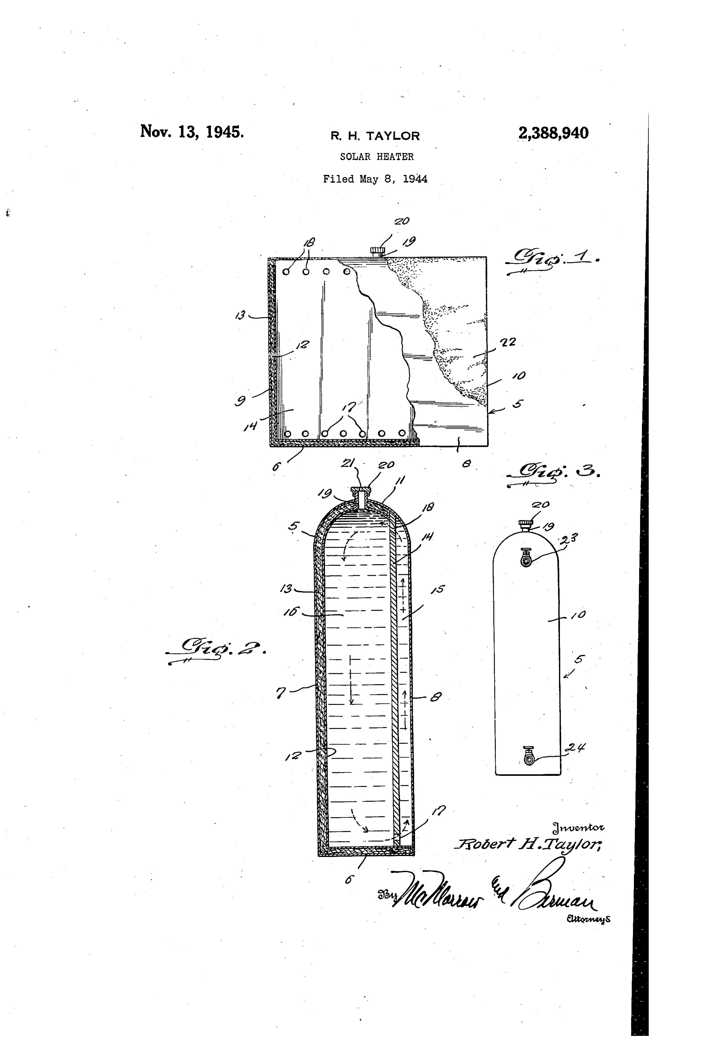
The present invention relates to new and use A partition f4 is positioned in the tank adja ful improvements in room heaters, and more par cent the front wall 8 and in Spaced relation ticularly a solar heater designed primarily to uti therefrom to provide a relatively narrow heating lize the heat rays from the sun to assist in home chamber 5 at the front of the tank and a rela heating after Sundown or during parts of the 5 tively larger storage chamber 6 between the par day when the sun is not shining. tition f4 and the rear of the tank, the partition An important object of the present invention 4 extending from the top to the bottom of the is to provide a self-contained Solar heater of this tank and from one end wall to the other thereof. character comprising a tank adapted to contain water or other liquids, and including a heater 0 of Openings 7 are formed adjacent the bottom the partition at spaced intervals and similar chamber and a storage chamber having open openings 8 are formed adjacent the top of the communication with each other and in which the partition.
water heated in the heater chamber is utilized The top of the liner f2 is formed with a filler to circulate the water through both chambers to neck 9 which extends outwardly through the top raise the temperature thereof when the heater i and is provided at its upper end with a thread chamber is subjected to the rays Of the Sun and ed cap 20 having a vent opening 2f therein. to radiate heat from the tank for a predeter The Outer surface of the front Wall 8 is COated mined period after being subjected to the influ with a dull black paint or other substance 22 (see ence of the Sun. Figure 1) possessing goods heat-absorbing quali A further important object of the invention is 20 ties and in the operation of the device the cham to provide a solar heater of this character adapt bers 5 and 6 are filled with water or other ed for use as a domestic hot water heater. suitable liquid and the front Wall 8 thereof then A still further object is to provide a device of placed in a position for exposure to the rays of this character simple and practical in construc tion, which is efficient and reliable in perform 25 the sun. The device may be placed in a room or other desired location.
ance, relatively inexpensive to manufacture and When the heating chamber 5 is subjected to install in operative position and otherwise, Well the rays of the sun, the water therein will become adapted for the purposes for which the same is quickly heated and cause a circulation thereof intended.
Other objects and advantages reside in the de through the chambers 5 and 6, as indicated by tails of construction and operation as more fully the arrows in Figure 2 of the drawing. The tem hereinafter described and claimed, reference perature of the water will thus be raised in ac being had to the accompanying drawing forming cordance sun and with the heat-generating power of the after the sun has gone down, or the part hereof, wherein like numerals refer to like heater otherwise is relieved of the influence of parts throughout, and in which: 35 the sun, the water in the chamber 5 will cool Figure 1 is a view in elevation with parts bro more quickly than the water in the chamber 6 ken away and shown in Section. and thus the circulation of the Water Will be Figure 2 is a vertical transverse sectional view reversed and the relatively warm water contained showing the device constructed for use as a room in the chamber 6 will then go back through the heater. 40 upper openings 8 in the partition 4 and down Figure 3 is a similar view showing the device wardly into the chamber 5 for utilizing the heat constructed as a domestic hot water heater. therefrom for heating the room by radiation from Referring now to the drawing in detail, where in for the purpose of illustration I have disclosed theInnon-insulated
Figure 3 of
Wall 8.
the drawing I have illustrated a preferred embodiment of the invention, the 45 numeral 5 designates a tank preferably con a heater adapted for attaching inlet and outlet structed of copper, aluminum or other good heat pipes 23 and 24 thereto for connection in a hot conducting material, the tank being of relatively water heating system and by means of which the narrow elongated construction and including a water heated in the tank may be used for do bottom 6, rear wall 7, front wall 8, end walls 9 50 mestic purposes. When used in this manner, the and 10 and a rounded top l. tank 5 is preferably placed on the roof of a build Positioned in the tank is a liner 2 Spaced from ing and the filler neck 9 and cap 20 may then be the bottom 6, rear wall 7 and top it and between omitted.
the liner and the said walls of the tank is packed It is believed the details of construction, Oper a suitable insulation material 3. SS ation and advantages of the device will be readily
Page 3
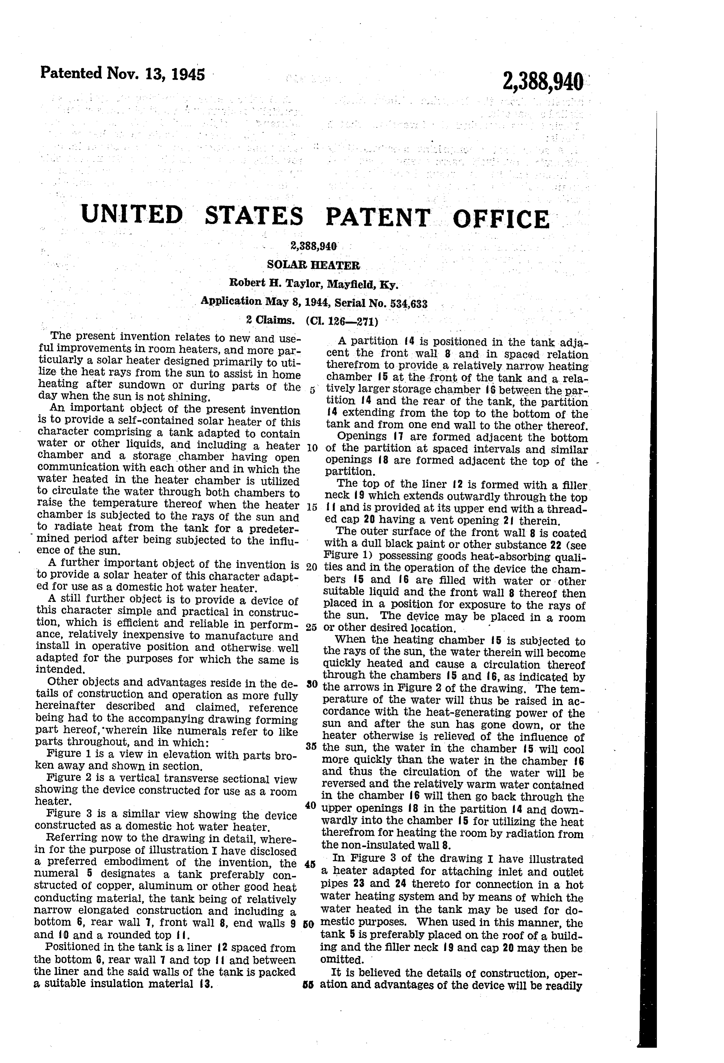
understood from the foregoing without further 2. A solar heater comprising an upright, sub detailed explanation. stantially rectangular, relatively narrow tank of Having thus described the invention, what I substantial height and length, arranged and adapted to contain a liquid to be heated, said
Claim is:
1. A solar heater comprising a substantially 5 tank being positioned in use with one of its nar rectangular, relatively narrow tank of substan rOW sides lowermost and its opposite narrow side tial height and length, arranged and adapted to uppermost, one of the major upstanding outer contain a liquid to be heated, said tank being Walls of the tank being heat conductive and with positioned in use with one of its narrow sides out insulation and all of the other outer walls O of the tank having inner linings spaced therefrom lowermost and the opposite narrow side upper with a filler of insulation material therebetween, most, one of the major outer walls of the tank and a partition located in said tank in relatively being heat conductive and exposed to the rays of the sun' and all of the other outer walls of the close spaced relation to said heat conductive Wall tank having inner linings spaced therefrom with but in greater spaced relation to the opposed a filler of insulation material therebetween, and 15 major upright wall so as to provide a relatively a partition located in said tank in relatively close narrow heating chamber and a storage cham spaced relation ber of substantial width and capacity, said par in greater spacedto relation said heatto conductive the oppositewall but, major titionV having a plurality of horizontal aligned insulated wall so as to provide a relatively nar openings adjacent its upper and lower sides, re row heating chamber and a storage chamber of 20 spectively, for circulation of the contained liquid in the tank from one of said cha. mbers to the substantial width and capacity, said partition having openings therethrough adjacent its op other.
posite upper and lower sides for the circulation ROBERT H. TAYLOR. of the contained liquid in the tank from one of 25 said chambers to the other.
Provenance
- Collection
- Cited prior art
- Original PDF
- patentimages.storage.googleapis.com →
- Filed
- 1944-05-08
- Pages
- 3
- Method
- pdftotext (the PDF's own text layer) + pdftoppm 300dpi page scans
- Source
- Google Patents bibliographic record
- Granted
- 1945-11-13
- Inventors
- Robert H Taylor
- Transcribed from
- patentimages.storage.googleapis.com →