patent · US552688
Distilling apparatus
7 January 1896
Page 1
Drawing sheet — no readable text.
Page 2
Drawing sheet — no readable text.
Page 3
UNITED STATES PATENT OFFICE.
IRA. H. JEWELL, OF CHICAGO, ILLINOIS.
DISTILLING APPARATUS.
SPECIFICATION forming part of Letters Patent No. 552,688, dated January 7, 1896. Application filed January 20, 1894, Renewed October 5, 1895, Serial No. 564,813, (No model) - Patented in Belgium January
To all typh???, i?; ??? ????ce7°?: serves to discharge the distilled water which Beit known that I, IRA. H. JEWELL, of Chi has been condensed Within said tube. A cago, in the county of Cook and State of Illi cap D provided with lateral perforations dis. nois, have invented certain new and useful employed to prevent drops thrown upward 55 Improvements in Distilling Apparatus, (for by violent ebullition of the water from enter which I obtained Letters Patent No. 82,273 ing the top of the tube, and a flange dº, lo in Belgium on the 13th day of January, 1894;) cated on said cap below the perforations d, and I do hereby declare that the following is serves to prevent any water from splashing full, clear, and exact description thereof, ref into the said apertures. I. ? erence being had to the accompanying draw.
Any suitable valve C' in the inlet a serves ings, and to the letters of reference marked to regulate the Water-Supply to the jacket A. thereon, which form a part of this specifica To prevent an undue quantity of water from
collecting in the boiler B, an overflow-open
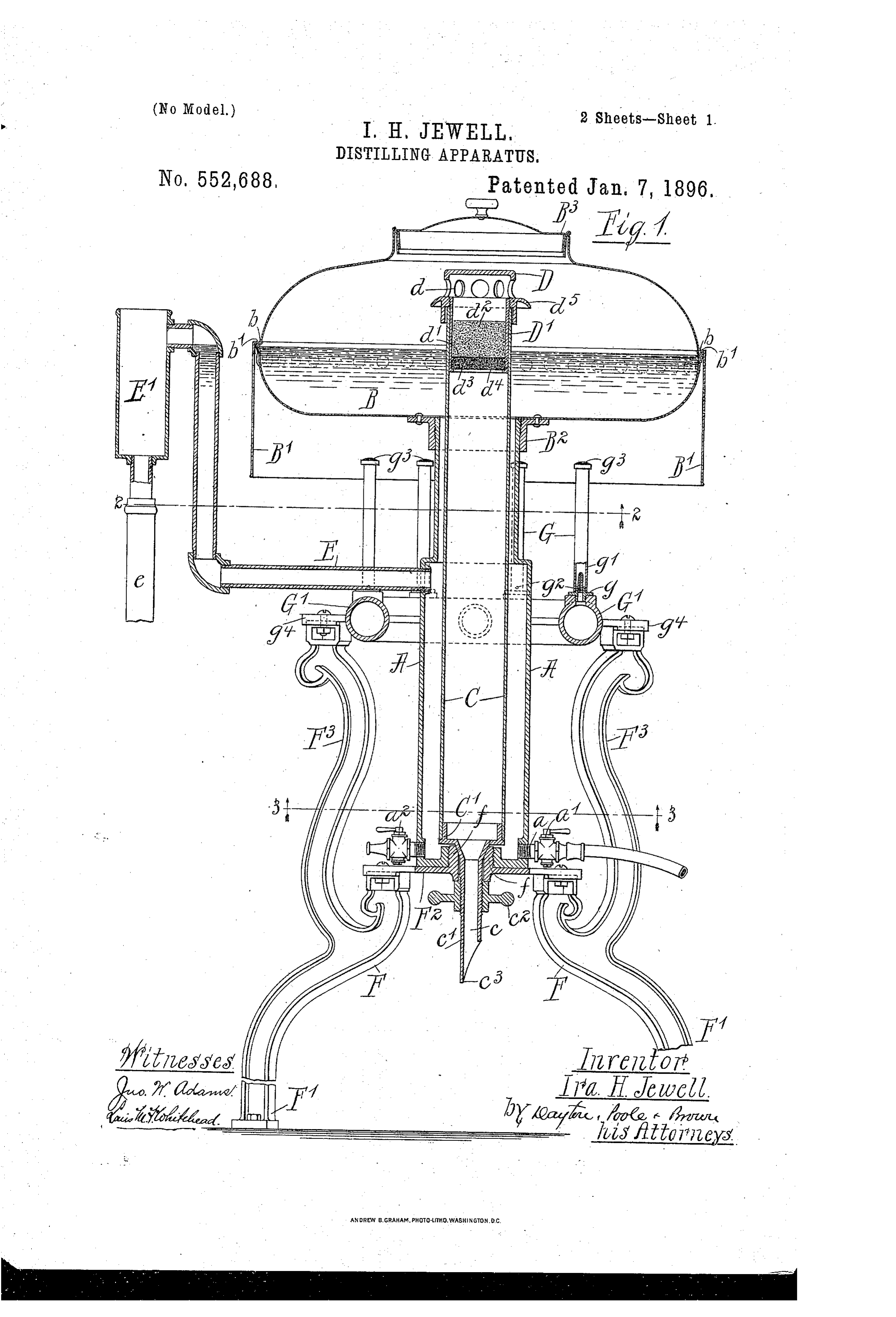
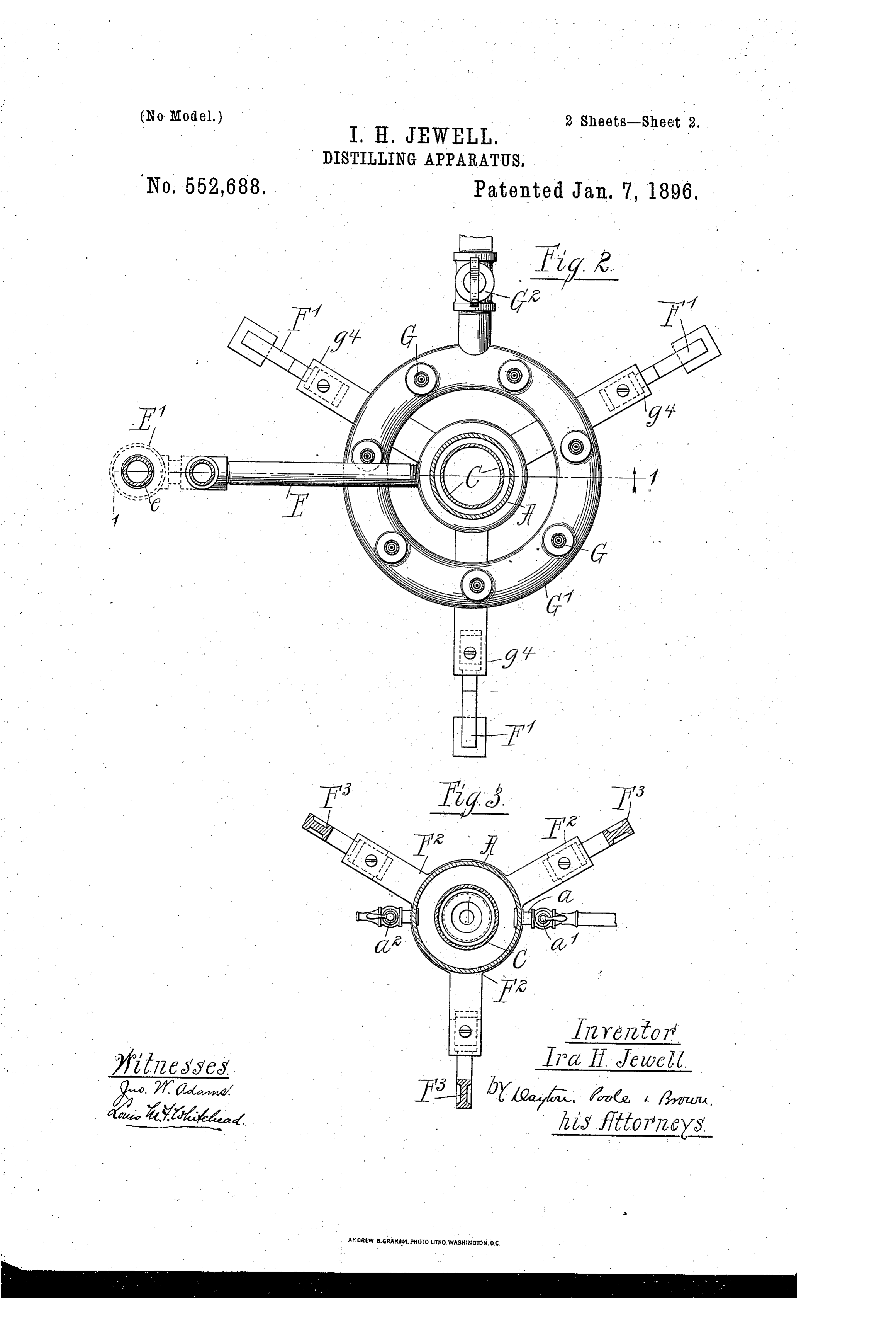
This invention relates to improvements in ing is provided, consisting, in this instance, distilling apparatus, and more particularly of a pipe Eleading outwardly and upwardly to a form of such apparatus suitable for pro from the jacket A and discharging laterally ducing distilled water. into the upper portion of an open cup E" at . The object of the invention is to provide the desired maximum level of the Water with 20 ashalldevice of the character referred to which in the boiler B. From the bottom of the cup be so inexpensive in construction and E" a suitable pipe e leads off to a sewer or simple and efficient in operation as to render convenient receptacle. The excess of water it suitable for household use. supply over that used in the boiler will es To this end the invention consists in the cape through the overflow thus provided, and matters hereinafter set forth and particularly the extent of the waste occasioned thereby 75 pointed out in the appended claims. may be at any time readily determined by In the accompanying drawings, Figure 1 is noticing the amount of Water flowing through a vertical section on line 1 1 of Fig. 2. Figs. the cup.
2 and 3 are horizontal sections on lines 22 As herein shown, the jacket A is mounted and 33, respectively, of Fig. 1. - . upon a supporting stand or frame F compris A designates an elongated upright tank, ing three legs F connected at their upper reservoir orjacket opening at the upper end ends by a horizontal plate Fsuitably secured into a closed vessel or boiler B, which, in the thereto. Said plate F, as herein shown, is form of the device illustrated, is circular and provided centrally with an upwardly-project is placed centrally over the tank or jacket ing screw-threaded hub f which enters a 35 and supported thereby. Within the jacket screw-threaded aperture in the lower end of A and extending axially thereof is an up the jacket A for rigidly fastening the jacket right condenser C, the external diameter of to the frame.
which is less than the internal diameter of Devices for heating the boiler B, as herein the tank or reservoir to provide an annular shown, comprise a plurality, in this instance 9o Water-space between them, so that the said seven, of gas-burners G arranged in a circle tank or reservoir constitutes in effect a wa beneath the boiler upon an annular pipe G'. ter-jacket surrounding said tube. The up Said burners are of the well-known Bunsen per end of the condenser C extends through type, comprising a shortinner nozzle g lead the open upper end of the jacket A into the ing from the pipe G' and an outer tube g'pro 95 boiler B and is itself left open at its upper vided at its base With apertures g for admit end to permit the entrance thereto of the ting air to mix with the gas discharged from steam or vapor formed in the boiler. An in the nozzle so as to produce a flame having let-opening Ct at the bottom of the jacket A great heating capacity. A cap g of Wire admits Water from any suitable source of Sup gauze covering the outer end of the tube g’ I OO ply, and an Outer passage c, leading through prevents the flame from entering the same. the bottom of the jacket from the tube C, The annular pipe G is in this instance cast
Page 4
with outwardly-projecting lugs g' which are made smaller in diameter than its base por secured to the upper ends of arms F on the tion in order to expose a greater portion of supporting-frame. An inlet-nozzle and Valve the bottom of the boiler to the action of the 7 O burners without greatly reducing the capacity
G° on the pipe G' admit gas thereto from any of the jacket. The boiler B is preferably suitable source of supply through a flexible hose or other convenient piping. made of copper or other suitable sheet metal In the operation of the apparatus water is and is herein shown as composed of upper and supplied to the jacket A through the inlet C. lower sections joined at their edges by a seam at its base, the supply being regulated by the which forms an outwardly-projecting annu IO valve a to properly supply the boiler and to lar bead b arou?nd the boiler. To confine the furnish a flow through the jacket and outlet heated products of combustion rising from pipe Esufficiently rapid to keep the condenser the burner-flames beneath the boiler, and to tube at a temperature low enough to secure protect the flames from drafts of air, a sheet So condensation of all the steam entering the metal hood. B' closely encircles the boiler and same. The burners C being lighted, steam is in this instance supported by an in Wardly will be formed within the boiler, and in the turned flange l'at its upper edge which rests absence of any other outlet will be forced by upon the bead b. The connection between its own pressure through the apertures d in the jacket and boiler is provided by means the cap D downwardly into the condenser of an interiorly-screw-threaded collar B, riv 2 ? tube C. Coming in contact with the wall of oted to the margins of an aperture in the bot said tube, which is maintained at a low tem tom of the boiler and engaged with exterior perature by the surrounding body of water screw-threads on the upper end of the jacket. in the jacket A, the steam will be rapidly A tight-fitting removable cover B in the top condensed. Since the natural tendency of of the boiler gives access to its interior. The steam is to rise, it will only move down into sheet-metal wall of the boiler is shown as bent the condenser-tube as it is forced down by to form a depending flange within which the the pressure in the boiler. Condensation will flange of the cover B closely fits. thus take place to a great extent in the upper As a further improvement the condenser 95 part of the tube, and when the parts are tube C is made readily removable so that the properly proportioned there will be no liabil parts may be easily cleansed from any adher ity of the steam being driven out uncondensed ent coating of calcareous or other matter through the outlet c. Moreover, the drops of which may become deposited thereon. To ? ? ? condensed water formed in the upper part of this end the bottom C of the tube (shown as the tube Will trickle down Over the cold walls a separate piece or casting secured thereto) 35 of the same until they emerge at the outlet c, is provided on its under side with a centural and, owing to the upward flow maintained in depending tubular projection c', which forms the jacket A and the consequent constant the outlet-passage c and extends through a accession of cold water at its base, the dis suitable aperture in the central hub f of the tilled water discharged from the apparatus plate E, being secured therein by a hand-nut will commonly be as cold, or nearly so, as the c', which engages an exterior screw-thread on water supplied to said jacket. the lower part of said projection and abuts As a further improvement the condenser C against the lower face of the said plate. To IO is in this instance provided at its upper end prevent leakage the tubular projection is with absorbent material for eliminating any made conical at its upper part, and the upper 45 noxious gases or Vapors which may pass off portion of the aperture in the hub f is simi with the steam. For this purpose the cap D larly shaped, so that as the nut c is screwed has secured within its lower part beneath the against the hub a water-tight joint is formed perforations d a short tube or cup D", adapted between the comical surfaces of the parts. I 5 to loosely fit the mouth of the said condenser The lower end of the tubular projection c' tube. Within the cup D" is a fine screen d", is beveled off to a point c in order to accu above which is provided a layer d of bone rately direct the drops of waterfalling there charcoal or equivalent material adapted to from into a suitable receptacle placed beneath. I 2 ? absorb noxious gases. To prevent any char the discharge-outlet. Being thus removably coal which may ooze through the screen d' secured the condenser may be lifted out of the 55 from passing down into the condenser, a shal jacket at any time by merely unscrewing the low layer d of coarse sand or quartz is pro hand-nut c, and by removing the cap D the vided between said screen d and a lower interior of the tube may be readily reached. screen d4 at the bottom of the cup D'. Ob The jacket A may, if necessary, be removed I 25 viously with this construction all the vapor from the stand by unscrewing it from the hub ?? arising from the heating of the water within f, but will ordinarily be cleaned without re the boiler must pass through the layer of char moval after the tube C and boiler B are de coal in entering the condenser-tube. The tached. A drain-cock a in the base of the noxious vapors will thereby be absorbed and jacket permits the apparatus to be emptied only the purified steam will be condensed. When desired.
Referring more particularly to the details The apparatus thus described, while par of construction shown in the accompanying ticularly adapted for household use in pro drawings, the upper part of the jacket A is ducing distilled water, may obviously be oth
Page 5
erwise employed in distilling water or for dis annular burner extending around the jacket tilling other liquids. h beneath the boiler, substantially as described. I have found the water produced by distill 4. A distilling apparatus comprising an up lation in the apparatus described to have su right tubular tank or water jacket provided perior qualities in respect toits taste and ac- i ceptability as a beverage without other aera with a supply inlet at its bottom, a circular boiler having a central aperture in its bottom tion than that produced in the operation of the apparatus. These qualities I believe to around secured, which the upper end of the jacket is a condenser tube located within the be due to the fact that carbonic-acid gas pro- i jacket and
II. ? duced from carbonaceous matters in the Wa extending at its upper end into 75 the boiler to a point above the Water level ter, as well as other gases, such as Oxygen therein, said condenser having a discharge driven off from the water in the act of boiling, outlet, and an annular fuel pipe surrounding are retained in the descending condensing the jacket beneath the boiler provided with pipe or tube and there remain admixed and a plurality of jets or burners, substantially 8o in contact with the steam or vapor and Water as described.
of condensation, so that they are largely ab-- 5. A distilling apparatus comprising an up sorbed or taken up by the water, with the re right tubular tank or water jacket having a sult of giving it a sparkling and pleasant as supply inlet at its lower end, a boiler pro distinguished from a flat or insipid taste. vided in its bottom with an aperture. With | 2 ? This desirable result, to whatever extentitis due to the presence of gases coming from the which the open upper end of the jacket is connected, and a straight, upright condenser water, is increased and augmented by the in tube located within the jacket and extending flow of atmospheric air through the outlet upwardly within the boiler to a point above passage and the dripping of the Water from the water line thereof, said condenser tube 25 said outlet-passage to the vessel placed there being detachably secured at its lower end to under to receive it. the jacket and having a discharge outlet I claim as my invention passing through the bottom Wall of the jacket, 1. A distilling apparatus comprising an up substantially as described. right tubular tank or Water jacket having a 6. A distilling apparatus comprising an up 95 supplyinlet at its bottom, a boiler the bottom right tank or Water jacket having a supply wall of which is attached to the open upper inlet at its base, a boiler provided in its bot end of said jacket, an upright tubular con tom with an aperture with which the open. denser located within the said jacket and ex upper end of the jacket is connected, and a tending at its upper end into the boiler and straight condenser tube located within the ?. ? ? 35 terminating above the Water line therein, said said jacket with its upper end opening into condenser being provided with a discharge the boiler above the top of the jacket and outlet at its bottom, substantially as de provided with a depending projection on its
2. A distilling apparatus comprising an up let, lower wall apertured to form a discharge out said projection being inserted through an right tubular tank or water jacket provided aperture in the bottom wall of the jacket and With a supply inlet at its bottom, a boiler pro having a conical surface which fits a corre vided with an aperture in its bottom around sponding surface on the said bottom Wall of which the upper open end of the jacket is se the jacket, and a nut or equivalent means cured, an upright tubular condenser located for holding said conical surfaces in contact II. ? 45 Within the jacket with its upper end extend with each other, substantially as described. ing into the boiler and terminating above the 7. A distilling apparatus comprising an up Water line thereof, said condenser being pro right tank or water jacket having a supply - vided with a discharge outlet at its lower end, inlet, a boiler into which said jacket opens and means for limiting the maximum depth. at its upper end and an upright condenser II 5 of Water in the boiler comprising a passage connected with the jacket and leading up tube located within the jacket and opening Wardly therefrom and an overflow orifice in jacket upper at its end into the boiler above the and provided at its lower end with a the said passage located above the level of the discharge outlet, and at its upper end with a boiler bottom and below the level of the top laterally apertured cap, substantially as de I 2 ? 55 of the said condenser, substantially as de Scribed.
Scribed. 8. A distilling apparatus comprising an up 3. A distilling apparatus comprising an up right tank or Water jacket having a supply right tubular tank or water jacket provided inlet, a boiler into which said jacket opens With a supply inlet at its bottom, a circular at its upper end, and an upright condenser 125 boiler having a central aperture in its bottom around which the upper end of the jacket is tube located within the jacket, opening at its upper' end into the boiler above the jacket
Secured, a condenser tube located within the and provided at its lower end with a discharge jacket and extending at its upper end into outlet, said tube having at its upper end a the boiler to a point above the water line laterally apertured cap provided with a pro thereof, said condenser being provided with tecting flange below the apertures therein, a discharge outlet at its lower end, and an substantially as described.
Page 6
9. A distilling apparatus comprising an up per end of said condenser through which right tubular tank or water jacket having a steam or vapor passes in entering the con supply inlet at its lower end, a boiler having denser, substantially as described. an opening in its bottom to which the upper In testimony that I claim the foregoing as open end of the jacket is attached, a con my invention I affix my signature in presence 15 denser within the jacket extending at its up of two Witnesses. IRA II. JEWELI. per end into the boiler to a point above the water level therein and provided at its bot Witnesses:
tom with a discharge outlet, and a mass or C. CLARENCE POOLE, Io body of absorbent material placed in the up ALBERT II. GRAVES.
Provenance
- Collection
- Cited prior art
- Original PDF
- patentimages.storage.googleapis.com →
- Pages
- 6
- Method
- pdftotext (the PDF's own text layer) + pdftoppm 300dpi page scans
- Source
- Google Patents bibliographic record
- Granted
- 1896-01-07
- Transcribed from
- patentimages.storage.googleapis.com →