patent · US4095997
Combined solar cell and hot air collector apparatus
20 June 1978
Page 1 — bibliographic record
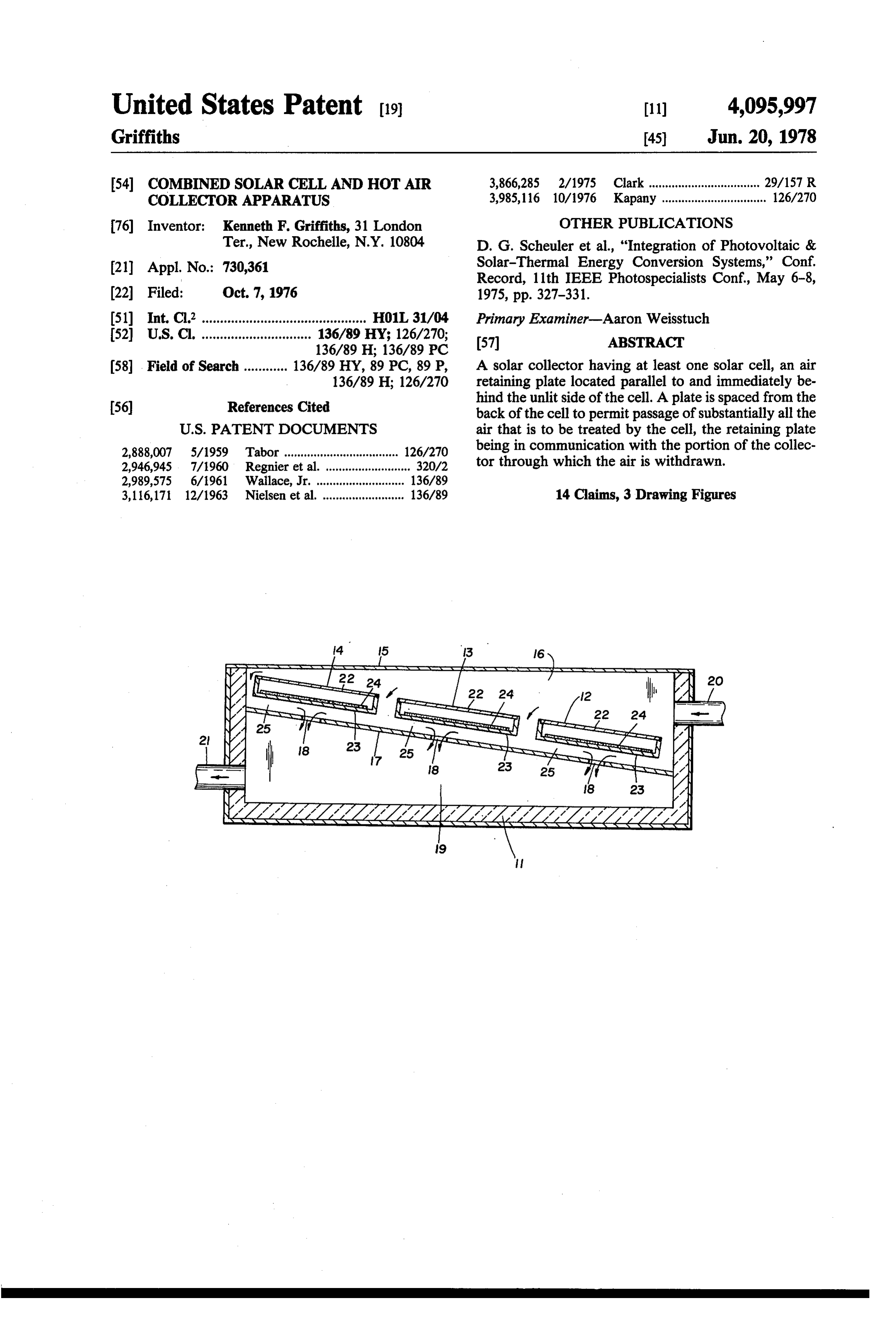
United States Patent (19) 11) 4,095,997 Griffiths 45) Jun. 20, 1978 54 COMBINED SOLAR CELL AND HOT AIR 3,866,285 2/1975 Clark .................................. 29/157 R COLLECTORAPPARATUS 3,985,116 10/1976 Kapany ................................ 126/270 76) Inventor: Kenneth F. Griffiths, 31 London OTHER PUBLICATIONS Ter, New Rochelle, N.Y. 10804 D. G. Scheuler et al., "Integration of Photovoltaic & (21) Appl. No.: 730,361 Solar-Thermal Energy Conversion Systems,' Conf. Record, 11th IEEE Photospecialists Conf, May 6-8, 22 Filed: Oct. 7, 1976 1975, pp. 327-331.
(51) Int. C.’............................................. HO1L 31/04 Primary Examiner-Aaron Weisstuch (52) U.S. C. .............................. 136/89 HY; 126/270; 57 ABSTRACT
58 Field of Search ............ 136/89 HY, 89 PC, 89 P, A solar collector having at least one solar cell, an air 136/89 H; 126/270 retaining plate located parallel to and immediately be 56) References Cited hind the unlit side of the cell. A plate is spaced from the back of the cell to permit passage of substantially all the
2,888,007 5/1959 Tabor ................................... 126/270 being in communication with the portion of the collec 2,946,945 7/1960 Regnier et al. ... on a 320/2 tor through which the air is withdrawn. 2,989,575 6/1961 Wallace, Jr. ....... ... 136/89 3.1617, 12/1963 Nielsenet al...O. 136/89 14 Claims, 3 Drawing Figures
Page 2
Drawing sheet — no readable text.
Page 3
as to effect the most efficient low cost cooling of photo
COMBINED SOLAR CELL AND HOT AIR voltaic electric cells.
COLLECTORAPPARATUS These objects, together with other objects and advan
BACKGROUND OF THE INVENTION
tages of the present invention will be apparent from the following disclosure,
The present invention relates to solar energy systems SUMMARY OF THE INVENTION and in particular to collectors for the heating of air and simultaneous production of electric power through According to the present invention, the rate of heat photovoltaic effect. transfer between the hot outer surface of a solar cell and The production of direct current electric power from 10 air to be heated by that cell is greatly augmented by suitable photovoltaic solar cells is a well known art. For providing an air retaining plate which is located parallel example, the use of silicon cells for producing electric to and immediately behind the unlighted backside of the cell. This plate need not be transparent; however, a power for space vehicles has been very successful. One space is left between the plate and the back of the cell of commercial system involves the use of a thin film of 15 just sufficient width to permit passage of substantially such high photo active material as copper-sulphide or all of the air cadmium-sulphide deposited on the lower inside surface provided for allowingto be heated by that cell. Also, means are of a hermetically sealed, double panel glass panel. When and means for withdrawing unheated air to enter this space such a panel intercepts sunlight, the photovoltaic film is portion of this space. Usually,heated air from another able to convert as much as 7% of the sunlight falling 20 into this space at the sides of the cell and air unheated is drawn heated air is upon the panel into useful electric power.
Solar cells also convert sunlight into heat, as well as discharged from the space through a suitable opening at another location under the cell.
electric energy. Therefore, heat as well as electric en As a result, the solar cells may be photovoltaic cells ergy can be a useful product from a system of one or mounted in a rectangular open box housing and each more solar cells.
It is well known that the efficiency of electric power 25 cell lel is provided with an air retaining plate located paral to and immediately under its unlit backside to form a production for almost all types of photovoltaic electric slot therewith and, having means to allow cold air to cells is increased by keeping the temperature of the enter the slot between the plate and the cell and means photovoltaic material as low as possible. On the other for discharging heated air from this slot. In many cases, hand, in cases in which hot air is to be obtained for such 30 this heated air would be collected in a suitable hot air applications as heating domestic hot water and space collection manifold. When such a manifold would be heating of buildings, it is desirable to produce the air at used, the air slots immediately adjacent to any surface areasonably high temperature such as 160 or even 200 of the cells would be narrow enough to insure that the F. In general these two criteria are opposites of each air velocity in those slots would be much greater than in other and there is not known any successful system in 35 the manifold. However, these slots should not be so which the optimum production of electricity and heat narrow that an unreasonable amount of pressure would are simultaneously obtained. be required to force air through the slots into the mani In conventional cases in which the heat by-product fold. When such a manifold would be used, it is pre from solar cells would be utilized to heat air, the cells ferred that all of the cold air entering the housing would would comprise the hot sunlit cover of a suitable collec do so through the slots. As a result of such forced pas tion box and cold air would usually be allowed to enter sage of air a lower and a more uniform temperature is the box at one end and heated air would leave the other maintained over all surfaces of the cell. end, passing through the spaces between the individual Full details of the present invention are set forth in solar cells. In the use of such a box, heat would be the following disclosure, and are shown in the accom transferred to the air inside mostly by radiation from the 45 panying drawing.
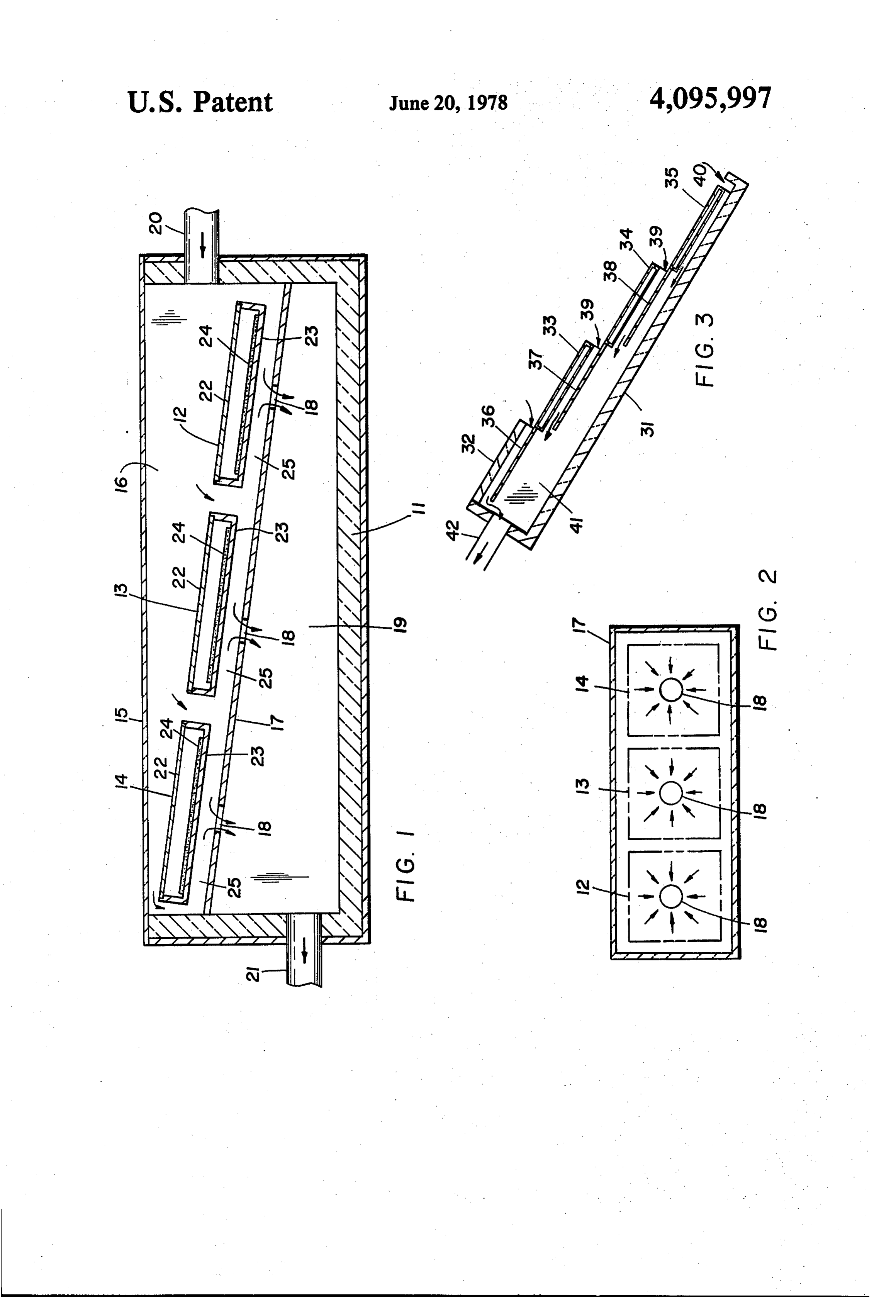
hot underside of the cells, and a large temperature dif BRIEF DESCRIPTION OF THE DRAWINGS ference would exist between the cooler air temperature in the box and the hot backside of the solar cells because In the drawings:
of poor heat transfer between the backside and the air in FIG. 1 is a sectional view along the longitudinal axis the box. All of this results in an excessively high temper 50 of a solar collector embodying the present invention; ature for the solar cells and above all would be contrary FIG. 2 is a sectional view along line 2-2 of FIG. 1 to efficient conversion of sunlight into electricity. showing a top planar view of the air distribution plate It is the object of the present invention to provide a within the collector; and combined solar air heating collector and solar energy FIG. 3 is a vertical section of another collector em electric power cell which primarily converts a maxi 55 bodying the present invention.
mum percentage of the intercepted sunlight energy into DESCRIPTION OF THE INVENTION useful electric power and at the same time produces as a by-product the hottest air possible. Referring to FIG. 1, a solar collector 11 is provided It is a further object of the present invention to in having an array of three solar cells 12, 13 and 14 aligned crease as much as possible the efficiency of transferring 60 in spaced stepped relationship. The body of collector 11 heat from a solar electric power cell to a stream of may consist of an open top box fabricated of a rigid flowing air, and to lower as much as possible the capital thermal insulation material such as urethane foam board cost per square foot of fabricated material which is used having a transparent cover 15. The cover is utilized to to augment efficient heat transfer from a solar cell to protect the solar cells from adverse weather and serves flowing air. It is another object of the present invention 65 as a cover for the space above the cells which form an to produce the hottest air possible with photovoltaic air distribution manifold 16. Supported below the cells cells while still maintaining an acceptably low tempera 12, 13 and 14, is an air retaining plate 17. The cells are ture of the photovoltaic material within the cell, as well substantially of coextensive width with the frame and
Page 4
may be supported angular to the horizontal axis, by under each cell is important to reduce the chances of brackets engaging their ends secured to the side walls of any hot spots forming in any portion of any cell. the frame or they may be supported on plate 17 by In some cases, the cold unheated air may be passed screws, brackets, clips or the like not shown in the directly from the ambient surroundings onto each of the drawings. The plate 17 is unitary and extends below all 5 cells without the use of inlet and outlet conduits which three cells. The backside of each cell is parallel to and establish the air flow. Thus the transparent cover 15 slightly above the top surface of plate 17. An air exit could be eliminated. This would allow slightly more opening 18 is provided in plate 17 below the center of light to reach film 24 but would prevent the collector each cell to allow heated air to pass downward into the from being able to utilize anything but ambient air as space between the plate 17 and the bottom of the box, 10 feed to the air heating slots.
forming a hot air collection manifold 19. In FIG. 2 the movement of air over air distribution The cold air distribution manifold 16 located above and heat retaining plate 17 is shown. The dotted lines the solar cells 12, 13 and 14 is fed relatively cool air show the edges of the solar cells 12, 13 and 14 which are through conduit 20 while the hot air collected in mani located above the plate 17. Cooling air flows through fold 19 located under air retaining plate 17 is discharged 15 the slot beneath each cell in a generally radial direction from conduit 21. Preferably the discharge is effected as shown by the arrows toward the central location of the a result of the air flow caused by the heating of the air opening 18.
in the collector, although the use of blowers, fans or the In FIG. 3, a solar collector 31 is shown, provided like could be made. with an array of four photovoltaic solar cells 32, 33, 34 Heat transfer between the hot backside of a solar 20 and 35, which are slightly different from those of FIG. photo-voltaic cell and an airstream flowing under it and 1. These cells may be mounted on and be supported in above an air retaining plate may be enhanced by a metal a suitable frame, which may be shaped like a box and finned heat dissipator. Such a dissipator may consist of may be fabricated of a stiff, boardlike thermal insula a metal plate which would have metal fins or prongs tion, such as composition board, e.g. masonite, or rigid projecting outward from one of its surfaces. The other 25 urethane foam. The central plane of each cell is shown surface of the dissipator may be flat and be placed to be parallel to that of every other cell in the array. against the flat unlighted backside of a photovoltaic However, these cells may be staggered along the depth cell. A suitable cement, which would have a high coeffi of the frame, from front to rear, as they are located from cient of thermal conductivity, may be used to thermally the bottom to top of the frame. Extending from each bond the heat dissipator to the backside of the cell. The 30 cell 33,34 and 35 except the upper one 32, there is a flat, height to which the fins or prongs would project out stationary, air retaining and distributing plate 36, 37 and ward from the plate which supports them would be 38, respectively, which is parallel to and is located just sufficient to enable them to reach substantially into the under the lower surface of the cell immediately above it slot, and just sufficient to contact the air retaining plate. to extend under its entire backside and form a narrow Therefore, all of the air flowing in the slot would flow 35 slot 39 sufficient to provide relatively high air velocity in close proximity to the fins or prongs. Naturally, the through it but not so narrow as to necessitate excessive heat dissipator would be preferably fabricated out of a pressure to drive air through it. The uppermost cell 32 metal, such as aluminum or copper which has a high of course is not provided with an air retaining or distrib coefficient of thermal conductivity. uting plate since there is no adjacent cell. Similarly, The production of electric current from sunlight is because of the absence of an adjacent cell to the lower possible by forming each of the cells 12, 13 and 14 as an most cell 35, the retaining and distributing plate 17 is enclosed somewhat flat hollow rectangular box having secured to the bottom wall of the frame 31. Each of the a transparent upper face 22 and a transparent lower face other air retaining plates is preferably integrally or uni 23 on which a film 23 of photo-voltaic material such as tarily attached to the upper edge of the associated cell silicon, copper sulphide or cadmium sulphide is spread. 45 below it in such a manner that air would not short cir The cells are each spaced above the distribution plate 17 cuit between it and the cell to which it is attached. The to provide a small slot 25 in communication with the lowermost cell 35 is spaced from the bottom edge of the openings 18. Suitable contacts, in accordance with frame to provide an air inlet corresponding to the inlets known technology are provided, but not shown, in the between the stepped cells, for relatively cool air, to pass drawings by which the current created in the cell is 50 through the slots 39 into a hot air collection manifold 41 tapped. defined by the bottom wall of the frame and the cells. When the solar collector shown in FIG. 1 is operat Preferably, all of the air which enters hot air collection ing, sunlight passes through transparent cover 15 and manifold 41 should do so through the slots under each the top glass layer 22 of each cell. This sunlight then of the four cells. Heated air is withdrawn from manifold impinges upon and is absorbed in photovoltaic material 55 41 through conduit 40 by means which would maintain comprising film 24. The heat generated in this film is manifold 41 at a lower pressure than that outside of the conducted downward through the lower glass plate 23 cells. A blower or even naturally induced thermal draft in each cell and is dissipated to the slot 25. is such suitable means.
Cold air from inlet 20 passes downward along the Cells 32,33,34 and 35 may be any suitable type which edges of each cell to the slot 25 under each cell where is able to generate electric power from sunlight and be it travels laterally to the opening 18 under each cell. fabricated in the form of a relatively flat sheet. The cells This air is heated as it travels laterally through the slot shown in FIG. 1 may be used. The air retaining plates under each cell and is fully heated by the time it passes may be of any relatively stiff material such as metal, out of openings 18. Preferably, the path of lateral air fiberboard or even glass.
flow under each cell is such that it passes in contact 65 The advantage of the inclined step arrangement of with all portions of the backside of the cell so that simul cells and air retaining plates shown in FIG. 3 is that rain taneously with its heating it effectively cools the cell or snow would not tend to enter the air slots and the air about its entire surface. Such distribution of air flow collection manifold.
Page 5
For example, a solar collector arranged as shown in feet per second through the slots. The height of the either FIG. 1 or FIG. 3 may be provided with photo stack top above the highest cells in the air manifold may voltaic cells, one foot by one foot square of double be as little as 20 feet or be as much as 200 feet. This paned, hermetically sealed, glass construction with a height may depend upon such considerations as the size photovoltaic film of copper sulphide, cadmium sulphide 5 and shape of the array of cells, the size and shape of the of suitable construction on the inside surface of the air collection manifold, the desired air velocity through lower glass pane. The air retaining plate may be alumi the slots, and the desired flow rate of airper square foot num and approximately inch of space may be pro of cell surface, and the intensity of sunlight (amount of vided between the upper surface of each aluminum concentration) upon the sunlit surface of the cells. plate and the lower surface of the cell immediately O In cases in which a stack is used and the warm air above it. The frame is fabricated of 2-inch thick ure rising in the stack serves to produce a draft, a generous thane foam board. A blower and a suitable damper are flow-rate of air may be allowed through each slot to provided to introduce and/or exhaust air from the man lower the average temperature of the cells as much as ifold at a controlled flowrate. possible. On the other hand, the flow rate of air through In FIG. 3, the total surface area of cells exposed to 15 the slots should not be so great as to decrease the tem sunlight is four square feet and when the solar collector is placed in bright sunlight which is nearly perpendicu perature in the stack to the point where the pressure drop through the slots would be too small. In most lar to the exposed surface of the cells and the blower is cases, the flow rate of air in the slots is self-regulating turned on and the damper is adjusted to allow 12 cubic and depends principally on the height of the stack and feet per minute of air to flow through the slots and out 20 of the manifold 41, the air velocity through the slots the wider width of the slots. The higher the stack and the the slots, the greater the flow rate of air through averages about 5 feet per second. As a result, heat trans the system fer from the bottom of each cell to the flowing air is cells and theper less square foot of cell area, the cooler the is the temperature difference between good and the pressure drop of the air flowing through the slots is reasonably small. After the system had been 25 the air in the stack and the ambient air outside. There working for the better part of one hour, thermal equilib fore, stack for any given system, the selection of the optimum height, slot width, arrangement of the array of rium is generally established. Under thermal equilib cells, the amount of concentration of sunlight upon the rium conditions, ambient air at 70 F. flowing into the slots is heated to 160 F. by the time it entered the hot cells and the type of metal dissipators to be used on the air manifold 41. The temperature of each of the cells 30 unlit sides of the cells is easily determined by heat trans fer engineers.
stayed below 200' F. It will be seen from the foregoing that in either of the It is contemplated that, in some instances, a collector embodiments, it is possible to enhance the heat transfer may have its hot air exhaust conduit 40 connected with between a suitable chimney or stack. This stack, which is not the heat retainingand the cells the flowing air by the provision of shown in FIG. 3, may be used to maintain a lower pres 35 the collector frameplate. in two, This plate effectively divides so that the air may be caused sure in the air collection manifold than in the space immediately in front of the photovoltaic cells. Such a to flow in sufficient volume over the cells, and through the area of highest heat (i.e., the slot 25 or 39) so that stack may be used particularly in situations in which the efficient heated air would be used only for the purpose of gener transfer of all of the heat into all of the flowing air is obtained while simultaneously isolating the cells ating a draft to help cool the cells. Such a system as this from may be of advantage in cases in which mirrors may be the hot air manifold section. The retaining plate, as used to concentrate sunlight upon the cells. In such a indicated, provides a large surface for dissipation of case, efficient air cooling of banks of cells without the heat to the moving stream below the cell. It will be thus use of power blowers to pump air would be of great appreciated that while the present invention can be advantage. The use of the stack of heated air serves 45 employed with any cell, it has particular application in very nicely to move air through the slots without the combination with photovoltaic cells. What is claimed:
use of powered blowers or fans. The use of this system may be highly advantageous in desert areas where: 1. A solar collector comprising a frome having a there would be no use of the heated air by-product; bottom wall and side walls defining a partially enclosed it would be advantageous to increase the electric 50 space, a heat producing solar cell located within the output of each square foot of cells by mirrors or frame and having one side exposed for illumination, said other light concentrating means without overheat solar cell being mounted to permit flow of air there ing the cells; around within the space, an air retaining plate mounted it would not be economical to use any electric power beneath the unlit side of said solar cell and spaced there to move air which would be utilized to cool the 55 from to provide a slot for movement of air therebe photovoltaic cells; tween, said plate being spaced from the bottom wall of the increased electric output per square foot of cell said frame to define therewith a sub-space for the reten would more than offset the added cost of air collec tion of air therein, and an outlet in said frame in commu tion manifold and vertical draft generating stacks. nication with the sub-space for the removal of air re In this case, probably nothermal insulation would tained therein.
be used for the manifold walls or the stack; or 2. The collector according to claim 1 wherein said electric power production would be the only desired solar cell is photovoltaic.
product and the air slots, the air collection mani 3. The collector according to claim 1, wherein said fold and the stacks would serve only for cooling plate is substantially coextensive with said frame and is the cells. 65 provided with at least one hole through which airflows In cases in which a stack is used to augment air draft from said slot to said outlet of said frame. through the slots, the stack need be only sufficiently 4. The collector according to claim 3, wherein said high to generate an air velocity in the range of 5 to 25 plate defines with the bottom wall of said frame a sub
Page 6
stantially enclosed heat storage area in communication spaced from said at least one cell to permit air to pass with said outlet of said frame. . beneath said at least one cell, and arranged to permit 5. The collector according to claim 1 including a said passing air to flow into the warm air zone. plurality of solar cells arranged in stepped relationship 9. The collector according to claim 8, wherein said to each other with a plate associated with each solar means for retaining the heat comprises a heat reflective cell, each plate secured from and extended in the plane plate made of an air impermeable material having a of the adjacent cell beneath the cell with which it is plurality of holes therein.
associated. 10. The collector according to claim 8, wherein said 6. The collector according to claim 5, wherein said holes are arranged substantially at the center of the plates are integrally formed with said cells from which O respective cells.
they extend. 11. The collector according to claim 8, wherein said 7. The collector according to claim 1, including a means for retaining the heat comprises a foraminous plurality of solar cells arranged in a generally common plate.
plane above said plate and to substantially fill the area 12. The collector according to claim 8, wherein said within the side walls of said frame. 15 cells are arranged in a stepped relationship staggered in 8. A solar collector comprising a frame formed as a the direction with respect to the bottom wall, and said substantially rectangular open box having bottom and heat retaining means comprises a plate made of air im side walls partially enclosing a space, at least one solar permeable material coextensive and associated respec cell mounted within said space, and arranged in a plane tively with each of said cells, the plate associated with set on an angle to the bottom wall to define a cool air 20 one cell being attached to the next adjacent cell except zone above said cells and a warm air zone below said for the last cell in said arrangement. cells, an inlet for cool air passing through at least one 13. The collector according to claim 8, including a side wall in communicaion with said cool air Zone and transparent cover for said frame.
an outlet passing through at least one side wall in com 14. The collector according to claim 8 including munication with said warm air zone, means located 25 means for maintaining the warm air zone at a pressure beneath each of said at least one cell for retaining at less than the cool air zone.
least in part the heat produced therein, said means being sk k
Provenance
- Collection
- Cited prior art
- Original PDF
- patentimages.storage.googleapis.com →
- Filed
- 1976-10-07
- Pages
- 6
- Method
- pdftotext (the PDF's own text layer) + pdftoppm 300dpi page scans
- Source
- Google Patents bibliographic record
- Granted
- 1978-06-20
- Inventors
- Kenneth F. Griffiths
- Transcribed from
- patentimages.storage.googleapis.com →